JP2005291567A - Sintering raw material charging apparatus and charging method - Google Patents
Sintering raw material charging apparatus and charging method Download PDFInfo
- Publication number
- JP2005291567A JP2005291567A JP2004104652A JP2004104652A JP2005291567A JP 2005291567 A JP2005291567 A JP 2005291567A JP 2004104652 A JP2004104652 A JP 2004104652A JP 2004104652 A JP2004104652 A JP 2004104652A JP 2005291567 A JP2005291567 A JP 2005291567A
- Authority
- JP
- Japan
- Prior art keywords
- rod
- chute
- raw material
- rods
- pallet
- Prior art date
- Legal status (The legal status is an assumption and is not a legal conclusion. Google has not performed a legal analysis and makes no representation as to the accuracy of the status listed.)
- Pending
Links
Images


Landscapes
- Manufacture And Refinement Of Metals (AREA)
Abstract
【課題】 スクリーン状シュートに付着した付着物を除去し、且つパレット上に適正な原料充填層を形成する。
【解決手段】 パレット幅方向と略平行な複数本のロッドを間隔をおいて並列させることでスクリーン状に構成され、且つ隣接するロッド間の間隔をシュート上部側ほど狭めたスクリーン状シュートを備えた装入装置において、ロッドの両端を保持した状態でパレット幅方向での移動が可能な2組のロッド保持・横行手段を設け、シュート長手方向で並列したロッド又は/及びロッド群を、ロッド毎又は/及びロッド群毎に、前記2組のロッド保持・横行手段に交互に保持させ、スクリーン状シュートの幅方向の少なくとも1箇所には、複数のロッドをシュート長手方向で一体に保持するロッドガイド部材を設けた。
【選択図】 図1PROBLEM TO BE SOLVED: To remove deposits adhering to a screen-like chute and to form an appropriate raw material packed layer on a pallet.
SOLUTION: A screen-like chute is configured by arranging a plurality of rods substantially parallel to the pallet width direction in parallel with a gap therebetween, and the gap between adjacent rods is narrowed toward the upper side of the chute. In the charging device, two sets of rod holding / traversing means capable of moving in the pallet width direction with both ends of the rod being held are provided, and the rods or / and rod groups arranged in parallel in the chute longitudinal direction are provided for each rod or / And a rod guide member that holds the plurality of rods integrally in the longitudinal direction of the chute at least at one place in the width direction of the screen-like chute, alternately held by the two sets of rod holding and traversing means for each rod group Was provided.
[Selection] Figure 1
Description
本発明は、高炉原料として使用される焼結鉱を製造するための焼結機において、移動するパレット上に焼結原料を粒度偏析状態で装入するための原料装入装置及びこの装置を用いた原料装入方法に関する。 The present invention is a sintering machine for producing sintered ore used as a blast furnace raw material. It relates to the raw material charging method.
高炉の主原料となる焼結鉱の製造設備として、ドワイトロイド式等の無端移動グレート式焼結機が広く使用されている。この焼結機を用いた焼結鉱の製造では、一般に、鉄鉱石にコークス粉と石灰粉等を混合して造粒した焼結原料(以下、単に“原料”という)を、原料装入装置によって連続移動するパレット上に層状に充填装入し、この原料充填層の表面を原料均し機構によって平坦化し且つ充填密度を均一化した後、原料充填層の表面に点火し、焼結工程に入る。ここで、原料充填層の表面の平坦性や充填密度の均一性は、成品焼結鉱の品質や歩留まり、さらには生産性に大きな影響を及ぼす。 As a manufacturing facility for sintered ore which is a main raw material of a blast furnace, an endless moving grate type sintering machine such as a Dwytroid type is widely used. In the production of sintered ore using this sintering machine, in general, raw materials charging equipment is used for sintering raw materials (hereinafter simply referred to as “raw materials”) that are granulated by mixing iron ore with coke powder and lime powder. In this way, the surface of the raw material packed layer is flattened by the raw material leveling mechanism and the packing density is made uniform, and then the surface of the raw material packed layer is ignited and subjected to the sintering process. enter. Here, the flatness of the surface of the raw material packed layer and the uniformity of the packing density have a great influence on the quality and yield of the product sintered ore and also on the productivity.
上記焼結機における従来の焼結鉱製造プロセスをより具体的に説明すると、まず、約5mm以下の擬似粒子状の原料(造粒物)を、原料装入装置の装入シュートによってパレット上に装入し、原料充填層を形成する。この原料充填層を上記のように原料均し機構で均した後、点火炉において原料充填層の表層部に含まれるコークス粉に点火する。一方、パレットの下方からブロアで空気を吸引し、原料充填層内のコークス粉を燃焼させながら、上層から下層に向けて鉄鉱石を焼成していく。このような焼成プロセスでは、原料充填層内での良好な通気性が確保されることが操業上重要な要素となる。 The conventional sinter production process in the above-mentioned sintering machine will be described more specifically. First, a pseudo-particle raw material (granulated material) of about 5 mm or less is placed on a pallet by a charging chute of the raw material charging device. The raw material filled layer is formed by charging. After this raw material packed layer is leveled by the raw material leveling mechanism as described above, the coke powder contained in the surface layer portion of the raw material packed layer is ignited in an ignition furnace. On the other hand, iron ore is fired from the upper layer to the lower layer while air is sucked from below the pallet with a blower and the coke powder in the raw material packed bed is burned. In such a firing process, ensuring good air permeability in the raw material packed bed is an important factor in operation.
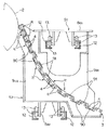
原料充填層の通気性を良好にするには、原料充填層内での原料の粒度分布を制御することが有効であり、具体的には、上層側ほど粒度の細かい原料が堆積するような状態になることが好ましい。このような粒度分布を実現するための装置として、図10に示されるような原料装入装置が知られている(例えば、特許文献1)。この原料装入装置は、ロールフィーダ等の原料供給機構20の下方に、反パレット移動方向に対して下向きに傾斜した粒度偏析装入用のスクリーン状シュート21を設けたもので、このスクリーン状シュート21は、パレット幅方向と平行な多数のロッド22を間隔をおいて並列させ、且つこれらロッド22の間隔をシュート上部側ほど狭めた構造を有している。また、上記多数のロッド22はパレット幅方向の複数箇所で、所定の間隔を保つようにロッド保持部材(図示せず)により一体に保持されている。
In order to improve the air permeability of the raw material packed layer, it is effective to control the particle size distribution of the raw material in the raw material packed layer, and specifically, a state in which a finer raw material is deposited on the upper layer side. It is preferable to become. As an apparatus for realizing such a particle size distribution, a raw material charging apparatus as shown in FIG. 10 is known (for example, Patent Document 1). This raw material charging apparatus is provided with a screen-
このような原料装入装置によれば、原料供給機構20から払い出されてスクリーン状シュート21上を滑り落ちる原料は、スクリーン状シュート21を構成するロッド22間の間隔がシュート上部側ほど小さいため、ロッド22間の間隙を通じてパレットP上に落下する際に粒度に応じて篩い分け(分級)され、粒度の大きい原料ほどパレットPの原料装入始端側に装入される。この結果、装入後の原料充填層は上層側ほど原料粒度が細かい粒度偏析した状態となる。
しかし、このようなスクリーン状シュートを有する装入装置では、焼結原料中の石灰粉やコークス粉等の原料粉がスクリーン状シュート21のロッド22に付着してロッド22間の間隙を閉鎖してしまい、この結果、スクリーン状シュート本来の機能(粒度偏析装入機能)が果たせなくなるという問題がある。
このような問題に対して、特許文献2には、スクリーン状シュートを構成するロッドの長手方向に沿ってスクレーパを往復運動させることによって、ロッドの付着物を掻き落とすようにした装置が提案されている。
In order to solve such a problem,
スクリーン状シュートの幅方向複数箇所には、ロッドを所定の間隔を保つようにシュート長手方向で全ロッドを一体に保持するロッド保持部材が設けられているが、このロッド保持部材の位置では、原料が落下すべきロッド間隙がないため、ロッド保持部材直下の原料充填層は原料充填密度の小さい原料堆積層となりやすい。原料充填層にこのような低密度充填領域が局所的に生じてしまうと、パレット幅方向での原料充填層の通気抵抗にバラツキを生じ、この結果、原料の焼成が不均一となって焼結鉱の歩留まりや生産性にも悪影響を与えてしまう。したがって、ロッド保持部材の設置数はなるべく少なくすることが望ましい。
ここで、特許文献2の装置では、複数のロッド保持部材間にそれぞれスクレーパを設置する必要があるが、このスクレーパは上述したロッド保持部材と同様に、原料の適正な堆積を阻害する部材となる。したがって、特許文献2の装置では、ロッド保持部材直下だけでなく、スクレーパ直下の原料充填層でも低密度充填領域が形成されてしまい、上述したような問題がさらに助長されてしまう問題がある。
At several locations in the width direction of the screen-like chute, rod holding members that hold all the rods integrally in the chute longitudinal direction so as to keep the rods at a predetermined interval are provided. Since there is no rod gap to drop, the raw material packed layer immediately below the rod holding member tends to be a raw material deposited layer having a low raw material packing density. If such a low density packed region is locally generated in the raw material packed layer, the air flow resistance of the raw material packed layer varies in the pallet width direction, resulting in uneven firing of the raw material and sintering. It will adversely affect the yield and productivity of the ore. Therefore, it is desirable to reduce the number of rod holding members installed as much as possible.
Here, in the apparatus of
したがって本発明の目的は、以上のような従来技術の課題を解消し、スクレーパなどのような特別な掻き取り手段をパレット上方で用いることなく、ロッドに付着した付着物を確実に除去することができ、これによりパレット上に適正な原料充填層を形成することができる原料装入装置及びこの装置を用いた原料装入方法を提供することにある。 Therefore, the object of the present invention is to eliminate the above-mentioned problems of the prior art and reliably remove the deposits attached to the rod without using a special scraping means such as a scraper above the pallet. It is possible to provide a raw material charging apparatus capable of forming an appropriate raw material packed layer on a pallet and a raw material charging method using this apparatus.
上記課題を解決するための本発明の原料装入装置及び原料装入方法の特徴は、以下のとおりである。
[1] 焼結機のパレット上に焼結原料を供給するための原料供給機構と、該原料供給機構から供給された焼結原料をパレット上に層厚方向で粒度偏析した状態に装入するためのシュートであって、反パレット移動方向に対して下向きに傾斜して設けられるスクリーン状シュートとを備え、該スクリーン状シュートは、パレット幅方向と略平行な複数本のロッドを間隔をおいて並列させることでスクリーン状に構成され、且つ隣接するロッド間の間隔又は/及び隣接する2本以上のロッドからなるロッド群間の間隔をシュート上部側ほど狭めた構成を有する焼結原料の装入装置において、
前記ロッドの両端を保持した状態でパレット幅方向での移動が可能な、2組のロッド保持・横行手段S1,S2を設けるとともに、シュート長手方向で並列したロッド又は/及び隣接する2本以上のロッドからなるロッド群を、ロッド毎又は/及びロッド群毎に、前記2組のロッド保持・横行手段S1,S2に交互に保持させ、
スクリーン状シュートの幅方向の少なくとも1箇所には、前記ロッドが挿通するガイド孔を有し、該ガイド孔にロッドをスライド可能に挿通させることで、複数本のロッドをシュート長手方向で一体に保持するロッドガイド部材を設けたことを特徴とする焼結原料の装入装置。
The features of the raw material charging apparatus and raw material charging method of the present invention for solving the above-described problems are as follows.
[1] A raw material supply mechanism for supplying a sintering raw material onto a pallet of a sintering machine, and a sintered raw material supplied from the raw material supply mechanism is charged into a state in which particle size segregation is performed on the pallet in the layer thickness direction. And a screen-like chute that is inclined downward with respect to the anti-pallet movement direction, the screen-like chute having a plurality of rods substantially parallel to the pallet width direction at intervals. Charging of the sintering raw material, which is configured in a screen shape by being arranged in parallel and has a configuration in which the interval between adjacent rods or / and the interval between rod groups composed of two or more adjacent rods is narrowed toward the upper side of the chute In the device
Two sets of rod holding and traversing means S1, S2 are provided which can move in the pallet width direction while holding both ends of the rod, and are arranged in parallel with the chute longitudinal direction or / and two or more adjacent rods. A rod group composed of rods is alternately held by the two sets of rod holding and traversing means S1, S2 for each rod and / or for each rod group,
At least one position in the width direction of the screen-like chute has a guide hole through which the rod is inserted, and the rods are slidably inserted into the guide hole so that a plurality of rods are integrally held in the chute longitudinal direction. An apparatus for charging a sintered material, characterized in that a rod guide member is provided.
[2] 上記[1]の装入装置において、シュート長手方向で並列したロッド又は/及び隣接する2〜3本のロッドからなるロッド群を、ロッド毎又は/及びロッド群毎に、2組のロッド保持・横行手段S1,S2に交互に保持させたことを特徴とする焼結原料の装入装置。
[3] 上記[1]又は[2]の装入装置において、ロッド保持・横行手段S1,S2が、それぞれ、パレット幅方向での移動が可能な台車と、該台車の駆動手段とを備えることを特徴とする焼結原料の装入装置。
[4] 上記[1]又は[2]の装入装置において、ロッド保持・横行手段S1,S2が、それぞれ、パレットの両側位置に配置されるパレット幅方向での移動が可能な1対の台車と、該両台車に設けられるロッド固定手段と、両台車を連結する連結体と、該連結体で連結された両台車を一体的に移動させるための駆動手段とを備えることを特徴とする焼結原料の装入装置。
[2] In the charging device according to [1], two sets of rods that are arranged in parallel in the chute longitudinal direction or / and adjacent two or three rods are provided for each rod or / and each rod group. A sintering raw material charging device characterized in that it is held alternately by rod holding and traversing means S1, S2.
[3] In the charging device according to [1] or [2], the rod holding / traversing means S1 and S2 each include a carriage capable of moving in the pallet width direction and a driving means for the carriage. An apparatus for charging sintered raw materials.
[4] In the charging device according to [1] or [2] above, a pair of carriages in which the rod holding / traversing means S1 and S2 can be moved in the pallet width direction, respectively, are arranged on both sides of the pallet. And a rod fixing means provided on the two carriages, a connecting body for connecting the two carriages, and a driving means for integrally moving the two trucks connected by the connecting body. Raw material charging equipment.
[5] 上記[1]〜[4]のいずれかの装入装置を用いて焼結機のパレット上に焼結原料を装入する方法であって、
スクリーン状シュートのロッドに付着した付着物を、ロッドをロッドガイド部材に対して移動させることにより、ロッドガイド部材で掻き取り除去する際に、ロッド保持・横行手段S1,S2を反対方向に同時に移動させることを特徴とする焼結原料の装入方法。
[5] A method of charging a sintering raw material onto a pallet of a sintering machine using the charging device according to any one of [1] to [4],
When the stick attached to the rod of the screen chute is scraped off by the rod guide member by moving the rod relative to the rod guide member, the rod holding / traversing means S1, S2 are simultaneously moved in the opposite direction. A method for charging a sintered raw material, characterized by comprising:
本発明の装入装置によれば、スクリーン状シュートのロッドを保持する2組のロッド保持・横行手段S1,S2をパレット幅方向で適宜横行移動させることだけで、ロッドに付着した付着物がロッドガイド部材により掻き取り除去される。本発明装置では、スクレーパなどのような特別な掻き取り手段をパレット上方で用いないため、スクリーン状シュート幅方向での焼結原料の落下状態を均一化でき、これによりパレット幅方向での焼結原料の充填密度を均一にすることができる。
また特に、本発明の原料装入方法によれば、ロッドに付着した付着物をロッドガイド部材で掻き取り除去する際に、ロッド保持・横行手段S1,S2を反対方向に同時に移動させることにより、付着物掻き取りに伴ってロッドガイド部材に作用する曲げ応力をパレット幅方向で均衡させ、ロッドガイド部材に作用する応力負荷を軽減することができる。このためロッドガイド部材の厚さを薄くすることができ、ロッドガイド部材直下での低密度充填領域(原料堆積層)の形成範囲を極力小さくすることができる。
According to the charging device of the present invention, the adhering material attached to the rod is removed by simply moving the two sets of rod holding and traversing means S1 and S2 for holding the screen-like chute rod in the pallet width direction. It is scraped off by the guide member. In the apparatus of the present invention, no special scraping means such as a scraper is used above the pallet, so that the falling state of the sintered raw material in the screen-like chute width direction can be made uniform, thereby sintering in the pallet width direction. The packing density of the raw material can be made uniform.
Further, in particular, according to the raw material charging method of the present invention, when scraping and removing the adhering matter adhering to the rod with the rod guide member, by simultaneously moving the rod holding and traversing means S1, S2 in the opposite directions, It is possible to balance the bending stress acting on the rod guide member in the pallet width direction as the deposits are scraped off, and to reduce the stress load acting on the rod guide member. For this reason, the thickness of the rod guide member can be reduced, and the formation range of the low density filling region (raw material deposition layer) immediately below the rod guide member can be minimized.
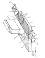
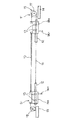
図1は、本発明の焼結原料(以下、単に“原料”という)の装入装置の一実施形態を模式的に示す斜視図である。図において、1は原料供給機構の一部を構成するロールフィーダ、2は同じく原料緩衝用の補助ロール、3は原料供給機構から供給された原料をパレット上に層厚方向で粒度偏析した状態に装入(充填)するためのスクリーン状シュートである。また、Pはスクリーン状シュート3の下方を通過するパレット、Sはパレット上に形成された原料充填層である。
FIG. 1 is a perspective view schematically showing one embodiment of a charging apparatus for a sintered raw material (hereinafter simply referred to as “raw material”) according to the present invention. In the figure, 1 is a roll feeder constituting a part of the raw material supply mechanism, 2 is also an auxiliary roll for buffering the raw material, and 3 is a state in which the raw material supplied from the raw material supply mechanism is segregated on the pallet in the layer thickness direction. It is a screen-like chute for charging (filling). P is a pallet passing under the screen-
前記スクリーン状シュート3(以下、単に“シュート3”という)は、前記ロールフィーダ1のほぼ真下の位置で、反パレット移動方向に対して下向きに傾斜して設けられている。前記ロールフィーダ1の上部には、下端が開放し且つ原料払出ゲート7を備えたサージホッパー6が配置されており、ロールフィーダ1の回転によって原料払出ゲート7から原料が払い出され、この原料は補助ロール2上に一旦落下して緩衝された後、回転する補助ロール2によりシュート3の上端に供給される。以上のような基本構成自体は、従来装置と同様である。
The screen-like chute 3 (hereinafter simply referred to as “
前記シュート3の本体は、パレット幅方向と略平行であって、且つ間隔をおいて並列した複数のロッド4を有しおり、このシュート3は、隣接するロッド間の間隙w(図5参照)がシュート上部側ほど狭くなるよう構成されている。なお、ロッド間の間隙は、隣接するロッド4間の間隙毎に順次狭くなるようにしてもよいし、隣接する複数本のロッドを1つの群とし、このロッド群間の間隙毎に順次狭くなるようにしてもよい。
The main body of the
前記複数のロッド4は、ロッドの両端を保持した状態でパレット幅方向での移動が可能な、2組のロッド保持・横行手段S1,S2で保持されている。より具体的には、これらロッド保持・横行手段S1,S2は上下に設けられ、シュート長手方向で並列したロッド4又は/及び隣接する2本以上のロッド4からなるロッド群Rが、ロッド毎又は/及びロッド群毎に、前記2組のロッド保持・横行手段S1,S2に交互に保持されている。図1の実施形態では実際よりもロッド数が少なく表されているが、隣接する2本のロッド4からなるロッド群Rがロッド保持・横行手段S1,S2に交互に保持されている。
なお、本発明においてロッド保持・横行手段S1,S2がパレット幅方向で移動可能であるとは、ロッド保持・横行手段S1,S2がパレットを横断して移動するという意味ではなく、パレット幅方向に沿った方向での移動が可能であるという意味である。
また、シュート3の幅方向の中央の1箇所には、前記ロッド4が挿通するガイド孔を有し、このガイド孔にロッド4をスライド可能に挿通させることで、複数のロッド4(全ロッド)をシュート長手方向で一体に保持するロッドガイド部材5が設けられている。
The plurality of
In the present invention, the fact that the rod holding / traversing means S1, S2 are movable in the pallet width direction does not mean that the rod holding / traversing means S1, S2 move across the pallet, but in the pallet width direction. This means that movement in the direction along the line is possible.
In addition, a guide hole through which the
ロッド保持・横行手段S1,S2が2本以上のロッド4からなるロッド群Rを交互に保持する場合、各ロッド群Rを構成するロッド4の本数に特別な制限はない。但し、本発明装置の好ましい使用形態では、ロッド4に付着した付着物をロッドガイド部材5で掻き取り除去する際に、ロッド保持・横行手段S1,S2を反対方向に同時に移動させ、これにより、付着物掻き取りに伴ってロッドガイド部材5に作用する曲げ応力をパレット幅方向で均衡させ、ロッドガイド部材5に作用する応力負荷を軽減するものである。このような応力負荷の軽減により、ロッドガイド部材5の厚さを薄くすることができ、ロッドガイド部材5直下での低密度充填領域(原料堆積層)の形成範囲を極力小さくすることができる。そして、上記のようにロッドガイド部材5に作用する応力負荷を適切に軽減するには、パレット幅方向で反対方向の応力が交互に作用するロッドガイド部材長手方向の範囲がなるべく短いことが好ましい。このような観点からして、ロッド群Rを構成するロッド数はなるべく最小単位に近いこと、すなわち2〜3本程度(好ましくは2本)とすることが好ましい。
When the rod holding / traversing means S1, S2 alternately hold the rod groups R composed of two or
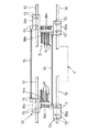
図2〜図6は、本発明の原料装入装置のより具体的な実施形態の一例を示すもので、図2は原料供給機構を省略した状態で示す平面図、図3は同じく正面図、図4は同じく側面図、図5はスクリーン状シュートを縦断面した状態で示す側面図、図6はロッド保持・横行手段を構成する台車の駆動手段を示す正面図である。
本実施形態における原料供給機構(ロールフィーダ1、補助ロール2)やスクリーン状シュート3の基本的な構成は図1のものと同様である。本実施形態では、ロッド保持・横行手段S1は構造体(図示せず)の上段に、ロッド保持・横行手段S2は同じく下段に、それぞれ配置されている。
FIGS. 2-6 shows an example of more concrete embodiment of the raw material charging apparatus of this invention, FIG. 2 is a top view which shows the state which abbreviate | omitted the raw material supply mechanism, FIG. 4 is a side view, FIG. 5 is a side view showing a screen-like chute in a longitudinal section, and FIG. 6 is a front view showing a dolly driving means constituting rod holding / traversing means.
The basic configuration of the raw material supply mechanism (roll
上段に配置された前記ロッド保持・横行手段S1は、パレットPの両側位置に配置されるパレット幅方向での移動が可能な1対の台車8a1,8b1と、これら両台車8a1,8b1に各々設けられるロッド固定板9a1,9b1(ロッド固定手段)と、両台車8a1,8b1を連結する1対の連結体10と、この連結体10で連結された台車8a1,8b1を一体的に移動させるための駆動機構11(駆動手段)とを備えている。
前記各台車8a1,8b1は走行用の車輪13を有し、構造体に設けられたレール12に沿って移動できる。
前記ロッド固定板9a1,9b1は、台車8a1,8b1の本体から下方に垂下した板状体であって、図4に示すようにシュート3の長手方向断面形状(ライン)に沿った形状の下端縁を有するとともに、この下端縁は長手方向に沿って櫛歯凹凸状に構成されている。この櫛歯凹凸状の下端縁は、後述する下段側のロッド保持・横行手段S2が有するロッド固定板9a2,9b2の櫛歯凹凸状の上端縁と適当な間隙をもって噛み合う。また、このロッド固定板9a1,9b1の櫛歯凹凸状の下端縁の凸部90が、各々ロッド4(ロッド群R)が連結される連結部となる。
The rod holding / traversing means S1 arranged in the upper stage is a pair of
Each of the
The rod fixing plates 9a 1 and 9b 1 are plate-like bodies hanging downward from the main bodies of the
前記連結体10は、本実施形態ではチェンなどの非剛体で構成され、1対の連結体10の各端が両台車8a1,8b1の幅方向両側に連結されている。なお、この連結体10は連結バーや形鋼材などの剛体で構成してもよい。
前記駆動機構11は、本実施形態(図6)では台車8b1側の構造体14に設けられた、駆動スプロケット17を備えた駆動装置15と、台車8a1側の構造体14に設けられた従動スプロケット18と、一端が台車8b1に連結され、前記駆動スプロケット17及び従動スプロケット18を経由して他端が台車8a1に連結されたチェン16を備え、駆動スプロケット17の正逆回転により連結体10で連結された台車8a1,8b1が一体としてパレット幅方向で移動できるようにしている。なお、この駆動機構11としては、シリンダ装置など任意の方式のものを採用できる。
In the present embodiment, the connecting
In the present embodiment (FIG. 6), the
下段に配置された前記ロッド保持・横行手段S2は、パレットPの両側位置に配置されるパレット幅方向での移動が可能な1対の台車8a2,8b2と、これら両台車8a2,8b2に各々設けられるロッド固定板9a2,9b2(ロッド固定手段)と、両台車8a2,8b2を連結する1対の連結体10と、この連結体10で連結された台車8a2,8b2を一体的に移動させるための駆動機構11(駆動手段)とを備えている。
前記各台車8a2,8b2は走行用の車輪13を有し、構造体に設けられたレール12に沿って移動できる。
前記ロッド固定板9a2,9b2は、台車8a2,8b2の本体に上方に向けて立設された板状体であって、図4に示すようにシュート3の長手方向断面形状(ライン)に沿った形状の上端縁を有するとともに、この上端縁は長手方向に沿って櫛歯凹凸状に構成されている。上述したように、この櫛歯凹凸状の上端縁は、上段側のロッド保持・横行手段S1が有するロッド固定板9a1,9b1の櫛歯凹凸状の下端縁と適当な間隙をもって噛み合っている。また、このロッド固定板9a2,9b2の櫛歯凹凸状の上端縁の凸部91が、各々ロッド4(ロッド群R)が連結される連結部となる。
The rod holding / traversing means S2 arranged in the lower stage is a pair of
Each of the
The rod fixing plates 9a 2 and 9b 2 are plate-like bodies erected upward on the main bodies of the
前記連結体10は、本実施形態ではチェンなどの非剛体で構成され、1対の連結体10の各端が両台車8a2,8b2の幅方向両側に連結されている。なお、この連結体10は連結バーや形鋼材などの剛体で構成してもよい。
ロッド保持・横行手段S2の駆動機構11は図示しないが、上段側の前記ロッド保持・横行手段S1と同様の構成(図6)を有している。
そして、図4に示すように、シュート長手方向で並列したロッド4のうち、隣接する2本のロッド4からなるロッド群Rの両端が、ロッド群毎に、前記ロッド保持・横行手段S1を構成するロッド固定板9a1,9b1の凸部90間と、ロッド保持・横行手段S2を構成するロッド固定板9a2,9b2の凸部91間に、交互に連結保持されている。
In the present embodiment, the connecting
The
As shown in FIG. 4, among the
シュート3の幅方向の中央の1箇所には、ロッドガイド部材5が設けられている。このロッドガイド部材5は細長の板状体で構成され、その長手方向に沿って複数のガイド孔50が適宜間隔をおいて貫設されている。そして、ロッドガイド部材5は、そのガイド孔50にロッド4をスライド可能に挿通させることで、全ロッド4をシュート長手方向で一体に保持している。ロッドガイド部材5は、その上端及び下端に連結部51,52を有しており、これら連結部51,52を介して図示しない構造部に保持されている。なお、ロッドガイド部材5は、さらに、パレットPの原料装入部の上方から外れたパレット両側方位置にそれぞれ設けてもよい。一方、先に述べたような理由から、原料充填層Sが形成されるパレットPの原料装入部上方に位置するロッドガイド部材5の設置数はなるべく少ない方が好ましく、多くても2箇所とすることが好ましい。
A
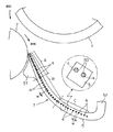
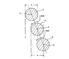
本発明の装入装置では、シュート上部側から落下する原料を所謂ソフト装入するために、図7に示すように、シュート上部側のロッド4は、上段側のロッド4の平面投影領域x(同領域xの境界線を含む)の中に、これと隣接する下段側のロッド4の中心軸aが含まれるような位置関係で配置されることが好ましい。図5に示すように、本実施形態では全ロッド36本のうち、シュート最上部のロッド4を含めた1/3(約33%)の本数(12本)のシュート上部側のロッド4(ロッド群A)を上記条件を満足するように配置してある。
このような配置を行うシュート上部側のロッド4(ロッド群A)の数や範囲は特に制限ないが、一般には、シュート3を構成する全ロッドのうち、シュート最上部のロッド4を含めた20〜35%、好ましくは25〜35%程度の本数のロッド4を対象とすることが好ましい。全ロッド数は特に制限はないが、30〜60本程度が普通である。
なお、下段側のロッド4の中心軸aの位置が、上段側のロッド4の平面投影領域xの中心にあまり寄りすぎると、ロッド間の間隙に原料が流入できなくなるおそれがあるので、上段側のロッド4と下段側のロッド4の両中心軸aの水平間距離は、上段側のロッド4の径の1/3〜1/2程度であることが好ましい。
In the charging apparatus of the present invention, in order to perform so-called soft charging of the raw material falling from the upper side of the chute, as shown in FIG. 7, the
The number and range of the upper chute rods 4 (rod group A) performing such an arrangement are not particularly limited, but in general, of all the rods constituting the
If the position of the central axis a of the
さらに、本発明の装入装置では、シュート下部側の複数のロッド4の径を、シュート上部側の複数のロッド4の径よりも小さくすることが好ましい。本実施形態では、全ロッド36本のうち、シュート最下部のロッド4を含めた1/3(約33%)の本数(12本)のシュート下部側のロッド4(ロッド群C)の径を、それよりもシュート上部側のロッド4(ロッド群B)の径よりも約25%程度小さくしている。
ロッド径を小さくするシュート下部側のロッド4(ロッド群C)の数や範囲は特に制限はないが、ロッドの撓み防止やシュートの重量などを勘案した場合、一般には、シュート3を構成する全ロッドのうち、シュート最下部のロッド4を含めた20〜50%、好ましくは25〜40%程度の本数のロッド4を対象とすることが好ましい。
また、シュート下部側のロッド4の径も特に制限はないが、ロッドの撓み防止やシュートの重量などを勘案した場合、一般には、シュート上部側のロッド4の径の60〜80%程度とすることが好ましい。シュート下部側及び上部側のロッド4の径としては、例えば、シュート下部側のロッド4の径:20〜30mm、シュート上部側のロッド4の径:12〜24mm程度を例示できる。
Furthermore, in the charging device of the present invention, it is preferable that the diameters of the plurality of
The number and range of the rods 4 (rod group C) on the lower side of the chute for reducing the rod diameter are not particularly limited. However, in consideration of prevention of rod deflection and the weight of the chute, in general, all of the components constituting the
Further, the diameter of the
シュート下部側の複数のロッド4の径を、シュート上部側の複数のロッド4の径よりも小さくするという条件は、種々の実施形態を採ることができ、本実施形態のようにロッド径をシュート上部側と下部側で2段階で変える場合の他に、例えば、シュート3を構成する各ロッド4の径又は/及び隣接する複数本のロッド4からなる各ロッド群のロッド径を、シュート上部側から下部側にかけて順次小さくすようにしてもよい。具体的には、以下のような形態を採ることができる。
(1) シュート3を構成する各ロッド4の径を、シュート上部側から下部側にかけて順次小さくする。
(2) シュート3を構成する各ロッド4を3つ以上のロッド群に分け、これらロッド群のロッド径を、シュート上部側から下部側にかけて順次小さくする。
また、上記(1)、(2)以外にも種々の形態を採ることができる。
Various conditions can be adopted for the condition that the diameters of the plurality of
(1) The diameter of each
(2) Each
In addition to the above (1) and (2), various forms can be adopted.
次に、本発明の装入装置の使用方法を上記実施形態を例に説明する。
本発明の装置では、ロッド4に原料粉が付着・堆積してきた時点で、ロッド保持・横行手段S1,S2をパレット幅方向で移動(横行)させてロッド4をロッドガイド部材5に対して移動させる。これによりロッド4に付着した付着物が、ロッドガイド部材5で掻き取り除去される。
このようにロッド4の付着物を除去する際には、ロッド保持・横行手段S1,S2を反対方向に同時に移動させることが好ましい。本発明装置では、シュート長手方向で並列するロッド4又は/及びロッド群Rを保持・横行手段S1,S2に交互に保持させているので、ロッド保持・横行手段S1,S2を反対方向に同時に移動させることにより、付着物掻き取りに伴ってロッドガイド部材5に作用する曲げ応力がパレット幅方向で均衡し、ロッドガイド部材5に作用する応力負荷を軽減することができる。このためロッドガイド部材5の厚さを薄くすることができ、ロッドガイド部材直下での低密度充填領域(原料堆積層)の形成範囲を極力小さくすることができる。
Next, a method for using the charging device of the present invention will be described using the above embodiment as an example.
In the apparatus of the present invention, when the raw material powder adheres and accumulates on the
Thus, when removing the deposits on the
次に、本実施形態の装入装置の他の作用効果について説明する。
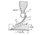
原料装入装置によりパレット上に原料を装入した場合、シュート上部側のロッドの間隙から粒径の小さい原料が落下し、この原料が原料充填層の表層部の構成することになる。しかし、このシュート上部側のロッド間隙から落下する原料は、シュートの最も高い位置から相当の落下速度で原料層上面に堆積するため、その堆積層が圧密状態となりやすく、このように粒径が小さい原料の堆積層が圧密状態になると、通気性の阻害要因となる。特に、原料充填層の表層部およびその近傍は、焼成の際の高温保持時間が短いことから、この部分で通気性が悪化すると焼成が十分になされず、成品焼結鉱の歩留まりを低下させる原因となりやすい。
Next, other functions and effects of the charging device of this embodiment will be described.
When the raw material is charged on the pallet by the raw material charging device, the raw material having a small particle size falls from the gap between the rods on the upper side of the chute, and this raw material constitutes the surface layer portion of the raw material packed layer. However, since the raw material falling from the rod gap on the upper side of the chute is deposited on the upper surface of the raw material layer at a considerable fall speed from the highest position of the chute, the deposited layer tends to be in a consolidated state, and thus the particle size is small. When the deposited layer of the raw material is in a consolidated state, it becomes an impediment to air permeability. In particular, the surface layer portion of the raw material packed layer and the vicinity thereof have a short high-temperature holding time during firing, and if the air permeability deteriorates in this portion, firing is not sufficiently performed, and the yield of the product sintered ore is reduced. It is easy to become.
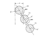
図8は従来装置におけるシュート上部側のロッド群での原料の流下状況を示している。同図が示すように、従来装置では、シュート上部側のロッド群は、下段側のロッド22の中心軸a′が上段側のロッド22の平面投影領域x′の外側に位置するような関係で配置されているため、ロッド間隙に流入する原料の多くが、下段側のロッド22であまり緩衝されることなく、すなわち、シュート上を落下してきた速度をあまり減殺されることなく、下方の原料層上に落下する。このため、その原料堆積層は圧密化を生じていたものである。これに対して本実施形態の装入装置では、図7に示すようにロッド間隙に流入する原料の多くが下段側のロッド4の上面に当たることにより緩衝されるため、落下速度が大きく減殺され、このため下方の原料層上に所謂ソフト装入され、この結果、原料堆積層の圧密化が防止されることになる。
FIG. 8 shows the flow of the raw material in the rod group on the upper side of the chute in the conventional apparatus. As shown in the figure, in the conventional apparatus, the rod group on the upper side of the chute has such a relationship that the central axis a ′ of the
また、原料装入装置によりパレット上に原料を装入する場合、粒度偏析によって通気性を良好なものにするという本来の目的からして、原料充填層の厚さ方向でなるべくきめ細かい粒度分布で精度良く偏析させることが好ましいが、この原料装入装置はロッド間の間隙で原料の分級を行うものであるため、分級の精度やこれに伴う粒度偏析の精度にも自ずと限界があり、特に、シュート下部側では原料の落下速度が大きくなるため、狙いとするようなきめ細かい粒度偏析状態が得られにくい。
図9は、装入装置のシュート下部側のロッド群による原料の分級状態を、本実施形態の装置(図9(a))と従来装置(図9(b))で比較して示したものであり、K1〜K4が各ロッド4,12の間隙から落下する原料の流れを示す。同図から判るように、本実施形態の装置のようにシュート下部側のロッド径を小さくすると、ロッド間隙は従来装置と同じであっても、シュート長手方向での単位長さ当たりのロッド間隙数が増え、この結果、シュート長手方向で原料のきめ細かい分級が可能となる。
In addition, when the raw material is charged on the pallet by the raw material charging device, the precision is achieved with the finest particle size distribution in the thickness direction of the raw material packed layer for the original purpose of improving air permeability by particle size segregation. Although it is preferable to segregate well, since this raw material charging device classifies the raw material in the gap between the rods, there is a limit to the accuracy of classification and the accompanying particle size segregation. Since the lowering speed of the raw material increases on the lower side, it is difficult to obtain a fine grain size segregation state as intended.
FIG. 9 shows the classification of the raw material by the rod group on the lower side of the chute of the charging device in comparison with the device of this embodiment (FIG. 9 (a)) and the conventional device (FIG. 9 (b)). K 1 to K 4 indicate the flow of the raw material falling from the gap between the
また、従来の原料装入装置のスクリーン状シュートは、ロッドを保持するためのロッド保持部材(本発明装置のロッドガイド部材に相当する部材)をパレット幅方向の複数箇所に設置しているが、先に述べたように、この保持部材はロッドの間隙から下方に流れ落ちる原料流れの均一性を阻害し、ロッド保持部材直下に低密度充填領域(原料堆積層)が形成される。したがって、このようなロッド保持部材が複数設置された従来装置では、それぞれのロッド保持部材直下に低密度充填領域が形成される結果、パレット幅方向での通気性に大きなバラツキを生じ、焼結鉱の成品歩留まりや生産性の低下を招いてしまう問題がある。このような問題に対しては、根本的にはロッド保持部材(パレットの原料装入部上方に位置するロッド保持部材)の設置数を少なくすればよいが、ロッド保持部材の設置数を少なくすると、シュート上を落下する原料の重みや衝撃によってロッドが撓んでロッド間隔に狂いを生じ、精度のよい分級ができなくなる。この結果、粒度偏析装入そのものに支障をきたしてしまう。このようなロッドの撓みを防止するためにはロッド径を大きくすればよいが、単純にロッド径を大きくするとシュートの大きさや重量が大幅に増加し、非実用的なものとなってしまう。 Further, the screen-like chute of the conventional raw material charging apparatus has rod holding members (members corresponding to the rod guide members of the present invention apparatus) for holding the rods installed at a plurality of locations in the pallet width direction. As described above, this holding member hinders the uniformity of the raw material flow flowing downward from the gap between the rods, and a low-density filling region (raw material deposition layer) is formed immediately below the rod holding member. Therefore, in a conventional apparatus in which a plurality of such rod holding members are installed, a low density filling region is formed immediately below each rod holding member, resulting in a large variation in air permeability in the pallet width direction, resulting in a sintered ore. There is a problem in that the product yield and productivity decrease. To solve this problem, the number of rod holding members (rod holding members positioned above the raw material charging portion of the pallet) should be reduced, but the number of rod holding members should be reduced. The rods bend due to the weight and impact of the raw material falling on the chute, causing an error in the rod spacing, and accurate classification cannot be performed. As a result, the particle size segregation charging itself is hindered. In order to prevent such bending of the rod, the rod diameter may be increased. However, if the rod diameter is simply increased, the size and weight of the chute are greatly increased, which becomes impractical.
このような問題に対して、本発明者らは、シュートを構成するロッドには、シュート長手方向での位置によって必要とされる強度に差があること、すなわち、シュート上部側のロッドはその上を多量の原料が通過するため、撓みを生じないように或る程度の径を有する必要があるが、シュート下部側のロッドについては、原料の通過量が少ないことから、シュート上部側ほど径を大くしなくてもよいことを実験等により確認した。このことから、本実施形態の装入装置のように、シュート下部側の複数のロッド4の径を、シュート上部側の複数のロッド4の径よりも小さくすることで、シュート3の大きさや重量を増大させることなく且つシュート本来の分級機能を損なうことなく、シュート3を構成するロッドガイド部材5の設置数を少なくすることができる。このため原料充填層の表層での低密度充填領域の形成を最小限に抑えることができ、パレット幅方向で均一な原料充填密度を得ることができる。
In order to solve such a problem, the present inventors have found that the strength of the rods constituting the chute differs depending on the position in the longitudinal direction of the chute, that is, the rod on the upper side of the chute Since a large amount of raw material passes through, it is necessary to have a certain diameter so as not to bend, but the rod on the lower side of the chute has a smaller diameter toward the upper side of the chute because the amount of raw material passing therethrough is small. It was confirmed by experiments and the like that it is not necessary to increase the size. From this, the size and weight of the
1 ロールフィーダ
2 補助ロール
3 スクリーン状シュート
4 ロッド
5 ロッドガイド部材
6 サージホッパー
7 原料払出ゲート
8a1,8b1,8a2,8b2 台車
9a1,9b1,9a2,9b2 ロッド固定板
10 連結体
11 駆動機構
12 レール
13 車輪
14 構造体
15 駆動装置
16 チェン
17,18 スプロケット
50 ガイド孔
51,52 連結部
90,91 凸部
a ロッド中心軸
x 平面投影領域
S1,S2 ロッド保持・横行手段
R ロッド群
A,B,C ロッド群
1
Claims (5)
前記ロッドの両端を保持した状態でパレット幅方向での移動が可能な、2組のロッド保持・横行手段S1,S2を設けるとともに、シュート長手方向で並列したロッド又は/及び隣接する2本以上のロッドからなるロッド群を、ロッド毎又は/及びロッド群毎に、前記2組のロッド保持・横行手段S1,S2に交互に保持させ、
スクリーン状シュートの幅方向の少なくとも1箇所には、前記ロッドが挿通するガイド孔を有し、該ガイド孔にロッドをスライド可能に挿通させることで、複数本のロッドをシュート長手方向で一体に保持するロッドガイド部材を設けたことを特徴とする焼結原料の装入装置。 A raw material supply mechanism for supplying a sintering raw material onto a pallet of a sintering machine, and a chute for charging the sintered raw material supplied from the raw material supply mechanism into a state in which the particle size is segregated in the layer thickness direction on the pallet And a screen-like chute provided to be inclined downward with respect to the anti-pallet moving direction, and the screen-like chute has a plurality of rods substantially parallel to the pallet width direction arranged in parallel at intervals. In the charging apparatus of the sintering raw material, which is configured in a screen shape and has a configuration in which the interval between adjacent rods or / and the interval between rod groups composed of two or more adjacent rods is narrowed toward the upper side of the chute,
Two sets of rod holding and traversing means S1, S2 are provided which can move in the pallet width direction while holding both ends of the rod, and are arranged in parallel with the chute longitudinal direction or / and two or more adjacent rods. A rod group composed of rods is alternately held by the two sets of rod holding and traversing means S1, S2 for each rod and / or for each rod group,
At least one position in the width direction of the screen-like chute has a guide hole through which the rod is inserted, and the rods are slidably inserted into the guide hole so that a plurality of rods are integrally held in the chute longitudinal direction. An apparatus for charging a sintered material, characterized in that a rod guide member is provided.
スクリーン状シュートのロッドに付着した付着物を、ロッドをロッドガイド部材に対して移動させることにより、ロッドガイド部材で掻き取り除去する際に、ロッド保持・横行手段S1,S2を反対方向に同時に移動させることを特徴とする焼結原料の装入方法。 A method of charging a sintering raw material onto a pallet of a sintering machine using the charging device according to any one of claims 1 to 4,
When the stick attached to the rod of the screen chute is scraped off by the rod guide member by moving the rod relative to the rod guide member, the rod holding / traversing means S1, S2 are simultaneously moved in the opposite direction. A method for charging a sintered raw material, characterized by comprising:
Priority Applications (1)
| Application Number | Priority Date | Filing Date | Title |
|---|---|---|---|
| JP2004104652A JP2005291567A (en) | 2004-03-31 | 2004-03-31 | Sintering raw material charging apparatus and charging method |
Applications Claiming Priority (1)
| Application Number | Priority Date | Filing Date | Title |
|---|---|---|---|
| JP2004104652A JP2005291567A (en) | 2004-03-31 | 2004-03-31 | Sintering raw material charging apparatus and charging method |
Publications (1)
| Publication Number | Publication Date |
|---|---|
| JP2005291567A true JP2005291567A (en) | 2005-10-20 |
Family
ID=35324694
Family Applications (1)
| Application Number | Title | Priority Date | Filing Date |
|---|---|---|---|
| JP2004104652A Pending JP2005291567A (en) | 2004-03-31 | 2004-03-31 | Sintering raw material charging apparatus and charging method |
Country Status (1)
| Country | Link |
|---|---|
| JP (1) | JP2005291567A (en) |
Cited By (4)
| Publication number | Priority date | Publication date | Assignee | Title |
|---|---|---|---|---|
| JP2007218470A (en) * | 2006-02-15 | 2007-08-30 | Nippon Steel Corp | Sintering machine |
| CN103484663A (en) * | 2013-08-23 | 2014-01-01 | 首钢总公司 | Method for measuring adhesion coefficient of sintering grate |
| KR101610283B1 (en) * | 2014-09-30 | 2016-04-07 | 주식회사 포스코 | Charging apparatus for raw material and removal method for extraneous matter thereof |
| CN114606380A (en) * | 2020-12-04 | 2022-06-10 | 上海梅山钢铁股份有限公司 | Material loosening device for improving sintering permeability and uniformity of thick iron ore powder material layer |
-
2004
- 2004-03-31 JP JP2004104652A patent/JP2005291567A/en active Pending
Cited By (4)
| Publication number | Priority date | Publication date | Assignee | Title |
|---|---|---|---|---|
| JP2007218470A (en) * | 2006-02-15 | 2007-08-30 | Nippon Steel Corp | Sintering machine |
| CN103484663A (en) * | 2013-08-23 | 2014-01-01 | 首钢总公司 | Method for measuring adhesion coefficient of sintering grate |
| KR101610283B1 (en) * | 2014-09-30 | 2016-04-07 | 주식회사 포스코 | Charging apparatus for raw material and removal method for extraneous matter thereof |
| CN114606380A (en) * | 2020-12-04 | 2022-06-10 | 上海梅山钢铁股份有限公司 | Material loosening device for improving sintering permeability and uniformity of thick iron ore powder material layer |
Similar Documents
| Publication | Publication Date | Title |
|---|---|---|
| JP5408179B2 (en) | Raw material charging equipment for sintering machine | |
| KR101235757B1 (en) | Apparatus for charging sintering material | |
| JP2005291567A (en) | Sintering raw material charging apparatus and charging method | |
| WO2012164889A1 (en) | Starting material charging device for blast furnace, and starting material charging method using same | |
| KR101460870B1 (en) | Apparatus for charging raw material in sintering machine | |
| US4871393A (en) | Apparatus and method for feeding sintering raw mix | |
| JP2005291537A (en) | Sintering raw material charging equipment | |
| JP5494512B2 (en) | Method of charging sintered raw materials | |
| EP2334829A1 (en) | Device for smoothing the surface of a sinter mixture | |
| EP2311997A1 (en) | Method and apparatus for charging raw material to be sintered | |
| JP2005291538A (en) | Sintering raw material charging equipment | |
| KR101223110B1 (en) | Apparatus for controlling height of ventilating bar | |
| JPH08267010A (en) | Raw material sieving method | |
| KR101010611B1 (en) | Attached Light Removal Device of Sintering Raw Material Loading Equipment | |
| JP2001329319A (en) | Sintering raw material charging method and charging device | |
| JPS6335348Y2 (en) | ||
| JP3257299B2 (en) | Raw material charging device for sintering machine | |
| JPH0638032B2 (en) | Air permeability adjusting device for sintering raw material layer | |
| JPH02195193A (en) | Charge device of sintered material | |
| JP2001227872A (en) | Raw material charging apparatus for sintering machine and method of using the same | |
| JPH0354398Y2 (en) | ||
| JPS6238227Y2 (en) | ||
| JPH08267009A (en) | Raw material sieving method | |
| JPH07229684A (en) | Sintering raw material charging device | |
| JP2000018836A (en) | Sintering material supply device |