JP2005291552A - Multi-air conditioner - Google Patents
Multi-air conditioner Download PDFInfo
- Publication number
- JP2005291552A JP2005291552A JP2004103872A JP2004103872A JP2005291552A JP 2005291552 A JP2005291552 A JP 2005291552A JP 2004103872 A JP2004103872 A JP 2004103872A JP 2004103872 A JP2004103872 A JP 2004103872A JP 2005291552 A JP2005291552 A JP 2005291552A
- Authority
- JP
- Japan
- Prior art keywords
- refrigerant
- compressor
- air conditioner
- indoor unit
- electronic expansion
- Prior art date
- Legal status (The legal status is an assumption and is not a legal conclusion. Google has not performed a legal analysis and makes no representation as to the accuracy of the status listed.)
- Granted
Links
Images

Landscapes
- Air Conditioning Control Device (AREA)
Abstract
Description
本発明は、空調運転(冷房運転、暖房運転及び除湿運転)により空調空気を噴出す複数の室内機ユニットを備え、各室内機ユニット毎に異なる運転制御が可能なマルチ型空気調和装置に関する。 The present invention relates to a multi-type air conditioner that includes a plurality of indoor unit units that eject conditioned air by air conditioning operation (cooling operation, heating operation, and dehumidifying operation) and that can perform different operation control for each indoor unit.
室内の冷暖房や除湿(以下、総称して「空調」と呼ぶ)を行う空気調和装置は、室内機ユニットと室外機ユニットとの間を冷媒配管及び電気配線で接続した構成とされる。このような空気調和装置は、圧縮機、室外熱交換器、絞り機構、室内熱交換器及び四方弁を主な構成要素として冷媒の循環回路を形成するヒートポンプを用いており、圧縮機から送出される冷媒の循環方向を四方弁の操作によって切り換えることで、所望の空調運転を行っている。
このような空気調和装置には、一式の室外機ユニットに対し、室内機ユニットが一台接続された構成のシングル型と、それぞれ独自の運転制御を可能にした室内機ユニットが複数接続された構成のマルチ型とがある。
An air conditioner that performs indoor air conditioning and dehumidification (hereinafter collectively referred to as “air conditioning”) has a configuration in which an indoor unit and an outdoor unit are connected by a refrigerant pipe and an electrical wiring. Such an air conditioner uses a heat pump that forms a refrigerant circulation circuit with a compressor, an outdoor heat exchanger, a throttle mechanism, an indoor heat exchanger, and a four-way valve as main components, and is sent from the compressor. The desired air conditioning operation is performed by switching the circulation direction of the refrigerant by operating the four-way valve.
In such an air conditioner, a single type of configuration in which one indoor unit is connected to a set of outdoor unit and a configuration in which a plurality of indoor unit units each enabling independent operation control are connected There are multiple types.
上述した空気調和装置において、圧縮機の潤滑に使用された潤滑油は、圧縮機内でミスト状となり、ガス冷媒と共に送出されて冷凍サイクルの冷媒循環経路内を循環する。このため、運転停止等により圧縮機以外の循環経路内に冷媒及び潤滑油が残留して溜まり込むことがあるので、従来よりこれを回収して溜まり込みにより冷媒及び潤滑油が不足するのを防止する保護制御が行われている。このような溜まり込みの問題は、室内機ユニットがそれぞれ独自の運転制御を行うため、運転中及び停止中の室内機ユニットが混在することに加えて、室内機ユニットまでの配管長が長く、しかも設置位置の高低差も大きくなる傾向にあることから、特に、マルチ型空気調和装置で生じやすい。 In the above-described air conditioner, the lubricating oil used for the lubrication of the compressor becomes mist in the compressor, is sent together with the gas refrigerant, and circulates in the refrigerant circulation path of the refrigeration cycle. For this reason, refrigerant and lubricating oil may remain and accumulate in the circulation path other than the compressor due to operation stop, etc., so that this is collected and prevented from deficient in the refrigerant and lubricating oil due to accumulation. Protection control is performed. The problem of such accumulation is that each indoor unit performs its own operation control, so that indoor units that are operating and stopped are mixed, and the piping length to the indoor unit is long. Since the height difference of the installation position tends to increase, it is particularly likely to occur in a multi-type air conditioner.
従来の空気調和装置においては、循環経路内の冷媒及び潤滑油を回収して溜まり込みを防止するため、下記の制御技術が実施されている。
(a)低回転数連続運転保護制御
圧縮機が連続して低回転数の運転を継続した場合、流出した冷媒及び潤滑油を回収する目的で、圧縮機の回転数を上昇させる。
(b)冷媒溜まり込み保護制御
マルチ型空気調和装置において、長時間連続して運転された場合、暖房運転を停止している室内機ユニットから冷媒及び潤滑油を回収する目的で実施する。この保護制御は、圧縮機の累積運転時間が所定時間(たとえば4時間)を経過した時点で、全ての室内機ユニットの電子膨張弁を全開にしてから圧縮機を運転することで回収運転を行う。
In the conventional air conditioner, the following control technique is implemented in order to collect the refrigerant and lubricating oil in the circulation path and prevent accumulation.
(A) Low rotation speed continuous operation protection control When the compressor continues to operate at a low rotation speed, the rotation speed of the compressor is increased for the purpose of collecting the refrigerant and lubricating oil that have flowed out.
(B) Refrigerant accumulation protection control When the multi-type air conditioner is operated continuously for a long time, it is carried out for the purpose of recovering refrigerant and lubricating oil from the indoor unit that has stopped the heating operation. In this protection control, when the cumulative operation time of the compressor has passed a predetermined time (for example, 4 hours), the recovery operation is performed by operating the compressors after fully opening the electronic expansion valves of all the indoor unit units. .
また、従来のマルチ型空気調和装置においては、選択された運転状態で冷媒ガスが循環しない圧縮機吐出側の冷媒管路に、管内凝縮した液冷媒とともに潤滑油が溜まり込むのを防止するため、同冷媒管路から分岐して圧縮機吸入側へ連結され、微少量の冷媒を溢流させるオイル戻し管路を設けたものが開示されている。この結果、微少量の冷媒が、圧縮機吐出側の冷媒管路及びオイル戻し管路を経由して圧縮機吸入側へ流れるので、冷媒及び潤滑油の溜まり込みを防止できるとされる。(たとえば、特許文献1参照)
しかしながら、上述した従来技術においては、次のような問題点が指摘されている。
(a)の低回転数連続運転保護制御では、複数の室内機ユニットを独自に運転制御するマルチ型空気調和装置に適用した場合、単に圧縮機の回転数を上げるだけであるから、回収対象となるのは運転中の室内機ユニットのみとなり、従って、停止中の室内機ユニットから冷媒及び潤滑油を回収することはできない。
(b)の冷媒溜まり込み保護制御では、本来の目的が停止ユニットの溜まり込みを防止することであるにもかかわらず、全ての室内機ユニットを運転している場合でも同様に実施されてしまうという問題点を有している。すなわち、全ての室内機ユニットを運転している場合は溜まり込みの心配がなく、しかも、保護運転実施中は適正な運転点から外れた運転となるため、空調フィーリングや圧縮機保護の観点からも保護制御を過剰に実施することは好ましくない。
However, the following problems have been pointed out in the above-described prior art.
In the low rotational speed continuous operation protection control in (a), when applied to a multi-type air conditioner that independently controls the operation of a plurality of indoor unit units, the rotational speed of the compressor is simply increased. Only the indoor unit in operation is made, and therefore refrigerant and lubricating oil cannot be recovered from the stopped indoor unit.
In the refrigerant pool protection control (b), although the original purpose is to prevent the stop unit from pooling, it is similarly implemented even when all the indoor unit units are in operation. Has a problem. In other words, when all indoor unit units are in operation, there is no worry of accumulation, and since the operation is out of the proper operating point during the protective operation, from the viewpoint of air conditioning feeling and compressor protection However, it is not preferable to carry out excessive protection control.
また、冷房運転の場合は、室内熱交換機内の冷媒を圧縮機で吸い込むため、同熱交換機内には冷媒及び潤滑油が溜まりにくい構成の冷媒循環系路となる。しかし、暖房運転の場合には循環方向が逆向きとなり、室内熱交換機内の冷媒が電子膨張弁を通過して圧縮機内に吸い込まれるように構成された冷媒循環系路となる。このため、暖房運転時の冷媒及び潤滑油は、圧縮機の吸い込みを受けても全閉状態の電子膨張弁に堰き止められるので、停止中の室内機ユニット内等に溜まり込みやすい。
また、保護制御のため停止している室内機ユニットの電子膨張弁を開けると、同室内機ユニット内を冷媒が流れて流動音を発生するので、運転停止中にもかかわらず運転騒音が発生するという不自然な現象が生じて好ましくない。
また、電子膨張弁を全開として絞らない状態で冷媒が循環するので、この冷媒が液相のまま圧縮機に流れ込むという液バックを生じやすい。このような液バックは、圧縮機破損の原因となるため好ましくない。
In the cooling operation, since the refrigerant in the indoor heat exchanger is sucked by the compressor, the refrigerant circulation system path is configured so that the refrigerant and the lubricating oil hardly accumulate in the heat exchanger. However, in the case of heating operation, the circulation direction is reversed, and a refrigerant circulation system configured such that the refrigerant in the indoor heat exchanger passes through the electronic expansion valve and is sucked into the compressor. For this reason, since the refrigerant and the lubricating oil during the heating operation are blocked by the fully-expanded electronic expansion valve even if the compressor is sucked in, the refrigerant and the lubricating oil are easily collected in the stopped indoor unit.
Also, if the electronic expansion valve of the indoor unit that is stopped for protection control is opened, the refrigerant flows through the indoor unit and generates a flow noise. The unnatural phenomenon that occurs is not preferable.
In addition, since the refrigerant circulates in a state where the electronic expansion valve is fully opened and is not throttled, a liquid back in which the refrigerant flows into the compressor in a liquid phase is likely to occur. Such a liquid bag is not preferable because it causes damage to the compressor.
このように、上述した従来の冷媒溜まり込み保護制御においては、全ての室内機ユニットが運転されて冷媒及び潤滑油の溜まり込みを心配する必要のない場合であっても、適正な運転点から外れて空調フィーリングや圧縮機保護の観点から好ましくない運転が行われるという問題点を有している。
本発明は、上記の事情に鑑みてなされたものであり、その目的とするところは、冷房運転及び暖房運転に係わらず、空調フィーリングを損なうことなく冷媒及び潤滑油を回収する保護制御を実施可能としたマルチ型空気調和装置を提供することにある。
As described above, in the conventional refrigerant pool protection control described above, even when all the indoor unit units are operated and it is not necessary to worry about the accumulation of the refrigerant and the lubricating oil, the control points deviate from the proper operation point. In view of air conditioning feeling and compressor protection, there is a problem that undesired operation is performed.
The present invention has been made in view of the above circumstances, and the object of the present invention is to implement protection control for recovering refrigerant and lubricating oil without impairing the air conditioning feeling regardless of the cooling operation and the heating operation. An object of the present invention is to provide a multi-type air conditioner that is made possible.
本発明は、上記の課題を解決するため、下記の手段を採用した。
本発明に係るマルチ型空気調和機は、室外機ユニットと、該室内機ユニットに接続されそれぞれ独自の運転制御を可能にした複数の室内機ユニットとを具備してなるマルチ型空気調和装置において、所定の条件を満たした空調運転の開始時を基準に積算される圧縮機実運転時間の累積時間(T)が所定の設定時間に達した場合に実施され、前記室内機ユニットの冷媒循環系路にそれぞれ設けられている電子膨張弁の全てを全開にして圧縮機を運転する冷媒溜まり込み保護制御運転モードを備えていることを特徴とするものである。
In order to solve the above problems, the present invention employs the following means.
A multi-type air conditioner according to the present invention is an multi-type air conditioner comprising an outdoor unit and a plurality of indoor unit units that are connected to the indoor unit and enable independent operation control. The refrigerant circulation path of the indoor unit is implemented when the cumulative time (T) of the compressor actual operation time accumulated on the basis of the start time of the air conditioning operation that satisfies the predetermined condition reaches a predetermined set time. Are provided with a refrigerant accumulation protection control operation mode in which the compressor is operated by fully opening all of the electronic expansion valves provided in each.
このようなマルチ型空気調和装置によれば、所定の条件を満たした空調運転の開始時を基準に積算される圧縮機実運転時間の累積時間(T)が所定の設定時間に達した場合に実施され、前記室内機ユニットの冷媒循環系路にそれぞれ設けられている電子膨張弁の全てを全開にして圧縮機を運転する冷媒溜まり込み保護制御運転モードを備えているので、冷房運転及び暖房運転を問わず、全ての室内機ユニットを含む冷媒循環系路を通って冷媒及び潤滑油が流れる。このため、停止中の室内機ユニット内等に溜まり込んでいた冷媒及び潤滑油は、この流れにより流出して圧縮機に戻る。 According to such a multi-type air conditioner, when the cumulative time (T) of the compressor actual operation time accumulated on the basis of the start time of the air-conditioning operation that satisfies the predetermined condition reaches a predetermined set time. Since it is provided with a refrigerant accumulation protection control operation mode in which all of the electronic expansion valves provided in the refrigerant circulation path of the indoor unit are fully opened and the compressor is operated, the cooling operation and the heating operation are provided. Regardless of the case, the refrigerant and the lubricating oil flow through the refrigerant circulation path including all the indoor unit units. For this reason, the refrigerant and lubricating oil accumulated in the stopped indoor unit and the like flow out by this flow and return to the compressor.
上述したマルチ型空気調和装置において、前記冷媒溜まり込み保護制御運転モードは、前記圧縮機の運転回転数をいったん最小まで落としてから前記電子膨張弁を全開にすることが好ましく、これにより、冷媒の循環量を必要最小限にして流動騒音を小さく抑えることができる。また、冷媒循環量が減少するので、電子膨張弁の全開により液相のまま圧縮機に流れ込む液バックを防止することもできる。 In the multi-type air conditioner described above, in the refrigerant accumulation protection control operation mode, it is preferable that the operation speed of the compressor is once reduced to a minimum and then the electronic expansion valve is fully opened. The flow noise can be kept small by minimizing the circulation amount. Further, since the refrigerant circulation amount is reduced, it is possible to prevent the liquid back flowing into the compressor in the liquid phase by fully opening the electronic expansion valve.
上述したマルチ型空気調和装置において、前記冷媒溜まり込み保護制御モードは、前記室内機ユニットが停止中の冷媒循環系路に設置されている電子膨張弁を全開とする前に、所定の遅れ時間を設けることが好ましく、これにより、圧縮機の回転数を低減して圧力比が減少した状態で電子膨張弁を全開とするため、冷媒流動音の騒音を小さくすることができる。すなわち、本来運転停止中のため運転騒音のない室内機ユニットから、保護制御のために発生する冷媒流動音を最小にして、不自然な運転騒音の違和感を低減することができる。 In the above-described multi-type air conditioner, the refrigerant accumulation protection control mode has a predetermined delay time before fully opening the electronic expansion valve installed in the refrigerant circulation system path where the indoor unit is stopped. Preferably, the electronic expansion valve is fully opened in a state where the number of rotations of the compressor is reduced and the pressure ratio is reduced, so that the noise of refrigerant flow noise can be reduced. That is, the refrigerant flow noise generated for protection control can be minimized from the indoor unit that does not have operation noise because the operation is originally stopped, and unnatural feeling of unnatural operation noise can be reduced.
上述したマルチ型空気調和装置において、前記冷媒溜まり込み保護制御モードの終了は、前記電子膨張弁の開度を保護制御開始前に戻した後、前記圧縮機の回転数を保護制御開始前に戻して完了することが好ましく、これにより、運転停止中の室内機ユニットでは冷媒流動音の運転騒音を防止でき、かつ、圧縮機に電子膨張弁で絞られない液冷媒が流入する液バックを防止できる。 In the multi-type air conditioner described above, the end of the refrigerant accumulation protection control mode is performed by returning the opening of the electronic expansion valve before the start of protection control and then returning the rotational speed of the compressor before the start of protection control. Thus, in the indoor unit that is stopped, it is possible to prevent the operation noise of the refrigerant flow noise and to prevent the liquid back in which the liquid refrigerant that cannot be throttled by the electronic expansion valve flows into the compressor. .
上述した本発明のマルチ型空気調和機は、所定の条件を満たした空調運転の開始時を基準に積算される圧縮機実運転時間の累積時間(T)が所定の設定時間に達した場合に実施され、室内機ユニットの冷媒循環系路にそれぞれ設けられている電子膨張弁の全てを全開にして圧縮機を運転する冷媒溜まり込み保護制御運転モードを備えているので、冷房運転及び暖房運転を問わず、全ての室内機ユニットを含む冷媒循環系路を通って冷媒及び潤滑油が流れ、停止中の室内機ユニット内に溜まり込んでいた冷媒及び潤滑油を圧縮機に戻して回収することができる。このため、停止中の室内機ユニットからも冷媒及び潤滑油の回収が可能となり、しかも、圧縮機実運転時間の累積時間毎に保護制御を実施するので、保護制御が頻繁に行われるようなことはない。従って、空調フィーリングを損なう運転や、適正な運転点から外れるという圧縮機にとって厳しい状態での運転が最小となるように減少させることができる。 The multi-type air conditioner according to the present invention described above is used when the cumulative time (T) of the compressor actual operation time accumulated on the basis of the start time of the air conditioning operation that satisfies the predetermined condition has reached a predetermined set time. Since it has a refrigerant accumulation protection control operation mode in which all the electronic expansion valves provided in the refrigerant circulation system path of the indoor unit are fully opened and the compressor is operated, the cooling operation and the heating operation are performed. Regardless, the refrigerant and lubricating oil flow through the refrigerant circulation system including all indoor unit units, and the refrigerant and lubricating oil accumulated in the stopped indoor unit units can be returned to the compressor and recovered. it can. For this reason, it is possible to recover the refrigerant and lubricating oil from the stopped indoor unit, and the protection control is performed every accumulated time of the compressor actual operation time, so that the protection control is frequently performed. There is no. Therefore, it is possible to reduce the operation that impairs the air conditioning feeling and the operation in a severe state for the compressor that is out of the proper operating point.
また、本発明の冷媒溜まり込み保護制御運転モードにおいては、下記の制御を行うことにより冷媒の流動音を小さく抑えることができる。特に、停止中の室内機ユニットから流動音が生じることはユーザーに違和感を与えるので、これを低減できることは商品性の向上に極めて有効である。
圧縮機の運転回転数をいったん最小まで落としてから電子膨張弁を全開にする
停止中の冷媒循環系路に設置されている電子膨張弁を全開とする前に所定の遅れ時間を設ける
冷媒溜まり込み保護制御モードの終了は、前記電子膨張弁の開度を保護制御開始前に戻した後、前記圧縮機の回転数を保護制御開始前に戻して完了する
In the refrigerant accumulation protection control operation mode of the present invention, the flow noise of the refrigerant can be suppressed by performing the following control. In particular, the generation of a flowing sound from a stopped indoor unit gives a sense of incongruity to the user. Therefore, reducing this noise is extremely effective for improving the merchantability.
Reducing the operating speed of the compressor to the minimum and then fully opening the electronic expansion valve Refrigerant pool providing a predetermined delay time before fully opening the electronic expansion valve installed in the stopped refrigerant circulation system The end of the protection control mode is completed by returning the opening of the electronic expansion valve before the start of protection control and then returning the rotational speed of the compressor before the start of protection control.
また、本発明の冷媒溜まり込み保護制御運転モードにおいては、電子膨張弁が全開した場合、冷媒循環量の減少により冷媒が液相のまま圧縮機に流れ込むという液バックを防止でき、さらに、全開の電子膨張弁で絞られない液冷媒が圧縮機に流入するという液バックを防止することもできるので、液バックを原因とする破損から圧縮機を保護することが可能になるという顕著な効果を奏する。 Further, in the refrigerant accumulation protection control operation mode of the present invention, when the electronic expansion valve is fully opened, it is possible to prevent the liquid back from flowing into the compressor in the liquid phase due to the decrease in the refrigerant circulation amount, and further, Since the liquid back that liquid refrigerant that cannot be throttled by the electronic expansion valve flows into the compressor can also be prevented, it is possible to protect the compressor from damage caused by the liquid back. .
以下、本発明に係るマルチ型空気調和装置の一実施形態を図面に基づいて説明する。
図1は、マルチ型空気調和装置の全体構成例を示す説明図である。このマルチ型空気調和装置は、室外機ユニット10と、同室外機ユニット10に接続された複数台の室内機ユニット20(図示の例では、室内機ユニット20A,20B、20Cの3台)とを具備して構成される。これら室内機ユニット10及び室外機ユニット20は、冷媒を流す冷媒配管21や図示しない電気配線等により接続されている。
Hereinafter, an embodiment of a multi-type air conditioner according to the present invention will be described with reference to the drawings.
FIG. 1 is an explanatory diagram illustrating an example of the overall configuration of a multi-type air conditioner. The multi-type air conditioner includes an
室外機ユニット10は、冷媒を圧縮して送出する圧縮機11と、冷媒の循環方向を切り換える四方弁12と、冷媒と外気との間で熱交換を行う室外熱交換器13と、絞り機構として機能する電子膨張弁14とを主な構成要素とし、さらに、消音の目的で圧縮機11の吐出側配管に配設されたマフラ15と、冷媒の気液分離等を目的として圧縮機11の吸入側配管に配設されたアキュムレータ16とを具備して構成される。この他にも、この室内機ユニット10には、たとえば図示省略の室外ファン、レシーバ、サービスバルブ及びストレーナ等の機器類や温度センサ等のセンサ類が設けられている。
The
室内機ユニット20は、ケーシング内に図示しない室内熱交換器や室内ファン等の機器を収納した構成とされる。この室内機ユニット10は、室内ファンで吸引した室内の空気を室内熱交換器に導いて通過させ、上述した室外機ユニット10から供給される冷媒との間で熱交換した空調空気を室内に吹き出すように構成されている。
3台の室内機ユニット20A,20B,20Cは、それぞれ室外機ユニット10内のヘッダー22,ディストリビュータ23で分岐した冷媒配管21A,21B,21Cに接続されている。また、室外機ユニット10内の各冷媒配管21A,21B,21Cには、それぞれ独立して動作する電子膨張弁14A,14B,14Cが、室外熱交換器13と室内ユニット20A,20B,20Cとの間に配設されている。
なお、上述したマルチ型空気調和装置では、各種の運転制御を行う図示省略の制御部が室外機ユニット10及び各室内機ユニット20に設けられている。
The indoor unit 20 is configured such that devices such as an indoor heat exchanger and an indoor fan (not shown) are housed in a casing. The
The three
In the multi-type air conditioner described above, a control unit (not shown) that performs various operation controls is provided in the
以下では、上述した構成のマルチ型空気調和装置の作用について、暖房運転時及び冷房運転時のそれぞれの場合に分けて説明する。
最初に、暖房運転時の作用について、図中に破線矢印で示した冷媒の流れとともに説明する。圧縮機11の圧縮で高温高圧の気体とされた冷媒は、マフラ15及び四方弁12を通り、冷媒配管21からヘッダー22に導かれる。このとき、冷媒の流れ方向(冷暖房の運転切り換え)は、四方弁12の設定位置に応じて選択切換えされる。
Below, the effect | action of the multi-type air conditioning apparatus of the structure mentioned above is divided and demonstrated in each case at the time of heating operation and air_conditionaing | cooling operation.
Initially, the effect | action at the time of heating operation is demonstrated with the flow of the refrigerant | coolant shown with the broken-line arrow in the figure. The refrigerant that has been compressed into the high-temperature and high-pressure gas by the
このヘッダー22では、冷媒が3つの冷媒配管21A,21B,21Cに分岐され、各流路に設けられた室内機ユニット20A,20B,20Cの室内熱交換器に送られる。なお、室内機ユニット20が運転停止の場合、各冷媒配管21A,21B,21Cに設けられている電子膨張弁14A,14B,14Cが全閉とされる。
運転中の室内機ユニット20内では、室内ファンにより吸込グリルから取り込まれた室内気に対して、室内熱交換器を通過する高温高圧の気体冷媒から熱が与えられる。これにより、室内機ユニット20の吹出口から温風が吹き出されることになる。
このような熱交換により、高温高圧の気体冷媒は、室内熱交換器において凝縮液化し、高温高圧の液冷媒となる。
In this
In the indoor unit 20 in operation, heat is given to the indoor air taken in from the suction grill by the indoor fan from the high-temperature and high-pressure gas refrigerant passing through the indoor heat exchanger. Thereby, warm air is blown out from the outlet of the indoor unit 20.
By such heat exchange, the high-temperature and high-pressure gaseous refrigerant is condensed and liquefied in the indoor heat exchanger, and becomes a high-temperature and high-pressure liquid refrigerant.
高温高圧の液冷媒は、冷媒配管21を通って室外機ユニット10の室外熱交換器13に送られるが、その途中で電子膨張弁14を通過する際に絞られて減圧される。こうして低温低圧の気液二相冷媒が室外熱交換器13に送られ、この気液二相冷媒は、室外熱交換器13を通過する際に外気から熱を奪うことになる。低温低圧の気液二相冷媒は、このことにより蒸発気化して低温低圧の気体冷媒となる。この気体冷媒がアキュムレータ16を経由して再び圧縮機11に送出され、以下上述した過程を繰り返すことになる。
The high-temperature and high-pressure liquid refrigerant is sent to the
次に、冷房運転時においては、四方弁12の設定位置を変えることにより、冷媒は上述した暖房運転時とは逆方向に冷媒回路中を流れる。すなわち、圧縮機11で高温高圧の気体とされた冷媒が、図中に実線矢印で示すように、四方弁12から冷媒配管21を通過して室外熱交換器13に送られ、室外気に熱を与えて凝縮液化し高温高圧の液冷媒となる。この高温高圧の液冷媒は、電子膨張弁14を通過して低温低圧の気液二相冷媒となり、再び冷媒配管21を通り室内機ユニット20の室内熱交換器に送られる。低温低圧の気液二相冷媒は、ここで室内気から熱を奪って当該室内気を冷却するとともに、冷媒自身は蒸発気化して低温低圧の気体冷媒となる。
Next, during the cooling operation, the refrigerant flows through the refrigerant circuit in the direction opposite to that during the heating operation described above by changing the setting position of the four-
この気体冷媒は、アキュムレータ16を経由して再び圧縮機11に送出され、以下同様の過程を繰り返すことになる。なお、この冷房運転時においても、運転停止中の室内機ユニット20に接続された電子膨張弁14は全閉とされる。
このような空調運転は、室外機ユニット10及び各室内機ユニット20内に収められた制御部が協調することによって制御される。
This gaseous refrigerant is sent again to the
Such an air conditioning operation is controlled by the cooperation of the control unit housed in the
さて、上述したマルチ型空気調和装置において、各室内機ユニット20A,20B,20Cは、それぞれ独自の運転制御が可能である。この場合の運転制御は、冷房運転または暖房運転の何れかが選択された場合において、ユニット毎の運転・停止が可能であることや独自の空調温度設定が可能であることなどを意味している。
このようなマルチ型空気調和装置には、所定の条件を満たした空調運転の開始時を基準に積算される圧縮機実運転時間の累積時間(T)が所定の設定時間に達した場合に実施され、室内機ユニット20の冷媒循環系路21にそれぞれ設けられている電子膨張弁14の全てを全開にして圧縮機11を運転する冷媒溜まり込み保護制御運転モード(以下、「保護制御運転モード」と呼ぶ)が設けられている。
Now, in the above-described multi-type air conditioner, each
Such a multi-type air conditioner is implemented when the cumulative operating time (T) of the compressor actual operation time accumulated on the basis of the start time of air-conditioning operation that satisfies a predetermined condition reaches a predetermined set time. The refrigerant accumulation protection control operation mode (hereinafter referred to as “protection control operation mode”) in which the
この保護制御運転モードは、冷房運転及び暖房運転の区別なくいずれの空調運転にも実施されるものであり、所定の条件を満たす空調運転の開始時から積算した累積時間(T)が所定値に達した時点で開始される。
ここで、累積時間(T)の積算を開始する条件(所定条件)を具体的に示す。
第1の条件は、マルチ型空気調和装置の電源が投入されて圧縮機11の運転を開始することである。この場合の運転開始は、冷媒を圧縮して送出する空調運転を開始することであるから、冷房運転(除湿運転を含む)及び暖房運転のいずれでもよい。
第2の条件は、マルチ型空気調和装置が運転中の場合であり、一つ前の保護制御運転モードが終了して通常の空調運転を開始することである。
This protection control operation mode is carried out in any air conditioning operation regardless of whether it is a cooling operation or a heating operation, and the accumulated time (T) accumulated from the start of the air conditioning operation satisfying a predetermined condition becomes a predetermined value. It starts when it is reached.
Here, a condition (predetermined condition) for starting accumulation of the accumulated time (T) is specifically shown.
The first condition is that the multi-type air conditioner is turned on to start the operation of the
The second condition is when the multi-type air conditioner is in operation, and the previous protection control operation mode ends and normal air conditioning operation starts.
上述した二つの条件(第1または第2の条件)のうち、何れか一方が満たされた時点を起点にして、圧縮機11の実運転時間について累積時間(T)の積算を開始する。圧縮機11の実運転時間は、3台の室内機ユニット20A,20B,20Cが全て運転されている場合の運転時間と、圧縮機11の回転数が0rps(すなわち停止中)である場合を除いた運転時間のことである。換言すれば、少なくとも1台の室内機ユニット20を停止状態にして、他の圧縮機11を少なくとも1台運転(回転数≠0)している状態の時間が実運転時間である。
ただし、このような累積時間(T)の積算は、停止中の室内機ユニット20が存在する運転状態から、所定時間を経過する前に全室内機ユニットが運転される状態に切り換わった場合には、積算した累積時間(T)はリセットされる。
Starting from the time when either one of the two conditions (first or second condition) described above is satisfied, integration of the accumulated time (T) is started for the actual operation time of the
However, such accumulation of accumulated time (T) is performed when the operation state in which the stopped indoor unit 20 exists is switched to a state in which all indoor unit units are operated before the predetermined time elapses. The accumulated cumulative time (T) is reset.
こうして圧縮機11の実運転時間を積算し、所定の累積時間(T)が経過すると、保護制御運転モードが開始される。この運転モードでは、全ての電子膨張弁14を全開として圧縮機11を運転する。すなわち、停止中の冷媒循環経路21に配設されて全閉となっている電子膨張弁14及び空調運転中のため所定の絞り開度に設定されている電子膨張弁14の全てが全開とされ、この状態で圧縮機11を運転して冷媒を循環させる。
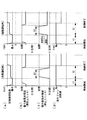
ここで、保護制御運転モードの具体的な制御例を図2に基づいて説明する。図2のタイムチャートは、(a)冷房運転時及び(b)暖房運転時のそれぞれについて、時間を横軸として上から順に、圧縮機回転数、電子膨張弁開度(運転ユニット)、電子膨張弁開度(停止ユニット)及び室外ファン回転数を示している。
Thus, the actual operation time of the
Here, a specific control example of the protection control operation mode will be described with reference to FIG. The time chart of FIG. 2 shows (a) during cooling operation and (b) during heating operation, with the time as the horizontal axis in order from the top, the compressor rotation speed, the electronic expansion valve opening (operation unit), and the electronic expansion. The valve opening (stop unit) and the outdoor fan speed are shown.
最初に、図2(a)に示した冷房運転時の制御について説明する。
この制御では、保護運転制御モードの制御開始と同時に、圧縮機回転数を圧縮機最小回転数Rmまで低下させる。この圧縮機最少回転数Rmは、圧縮機11が停止することなく回転可能な値であり、圧縮機11の仕様等諸条件により決められる。
また、圧縮機11の回転数低下が完了するのと同時に、室内機ユニット20が空調運転中の冷媒循環系統(冷媒配管21)にある電子膨張弁14は、その開度が全開とされる。なお、以下の説明においては、運転中の室内機ユニット20を「運転ユニット」と呼び、停止中の室内機ユニット20を「停止ユニット」と呼ぶことにする。
First, the control during the cooling operation shown in FIG.
In this control, simultaneously with the start of control in the protective operation control mode, the compressor rotational speed is reduced to the compressor minimum rotational speed Rm. This compressor minimum rotation speed Rm is a value that allows the
Further, at the same time when the rotation speed reduction of the
こうして圧縮機11を最小回転数Rmで運転するとともに、運転ユニット20の電子膨張弁14を全開として所定時間t1(たとえば60秒程度)の運転を継続した後、停止ユニット20の電子膨張弁14についても同様に全開とし、かつ、圧縮機11の回転数を冷媒循環最小回転数R1まで上昇させる。この冷媒循環最小回転数R1は、電子膨張弁14をすべて全開としたことにより、冷媒が全ての冷媒循環経路を循環できる必要最小限の値である。換言すれば、冷媒循環最小回転数R1は、停止ユニット及びその冷媒循環経路内等に溜まり込んでいる冷媒及び潤滑油を回収できるだけの流れを生じさせることが可能な最小の回転数である。
In this way, the
この結果、マルチ型空気調和装置においては、全ての電子膨張弁14を全開として圧縮機11を冷媒循環最小回転数R1で運転することにより、全ての室内機ユニット20を含めた冷媒循環経路を冷媒が循環することとなる。このような冷媒の循環は、所定時間t2(たとえば120秒程度)の間だけ継続される。このような冷媒循環により、特に停止ユニットに溜まり込んでいた冷媒及び潤滑油の回収が可能になる。
こうして溜まり込み冷媒及び潤滑油を回収する運転(以下、「回収運転」と呼ぶ)が完了すると、圧縮機11の回転数は元の状態(保護制御運転モード開始前の状態)に戻される。
As a result, in the multi-type air conditioner, all the electronic expansion valves 14 are fully opened and the
When the operation for recovering the accumulated refrigerant and lubricating oil (hereinafter referred to as “recovery operation”) is completed in this way, the rotational speed of the
一方、電子膨張弁14の開度については、所定時間t2が経過する前に、次のようにして元の状態に戻される。
停止ユニットの電子膨張弁14は、所定時間t2の回収運転が完了する前に、元の状態である全閉に戻される。すなわち、停止ユニットの電子膨張弁14は、回収運転の完了により圧縮機11を元の回転数に戻す前に、所定時間t2より短いt3の回収運転時間経過後に保護制御運転モード開始前の状態である全閉に戻される。
また、運転ユニットの電子膨張弁14についても、停止ユニットの電子膨張弁14が全閉になるのと同時に動作して、所定時間t2の回収運転が完了する前に元の開度に戻される。すなわち、所定時間t2の回収運転が完了して圧縮機11の回転数を元に戻す前に、全ての電子膨張弁14は元の状態に戻っている。
On the other hand, the opening degree of the electronic expansion valve 14 is returned to the original state as follows before the predetermined time t2 elapses.
The electronic expansion valve 14 of the stop unit is returned to the fully closed state in the original state before the recovery operation for the predetermined time t2 is completed. That is, the electronic expansion valve 14 of the stop unit is in a state before the start of the protection control operation mode after the recovery operation time of t3 shorter than the predetermined time t2 elapses before the
Also, the electronic expansion valve 14 of the operation unit operates at the same time as the electronic expansion valve 14 of the stop unit is fully closed, and is returned to the original opening degree before the collection operation for the predetermined time t2 is completed. That is, before the recovery operation for the predetermined time t2 is completed and the rotation speed of the
また、図2(b)に示す暖房運転時の制御についても、上述した冷房運転時と同様の制御がなされるので、ここではその詳細な説明を省略する。
なお、冷暖房運転時において、室外ファンについては上述した回収運転中に回転数を上げる運転がなされ、また、回収運転終了後の所定時間については、デフロスト運転の禁止時間帯とする。
Further, the control during the heating operation shown in FIG. 2B is also performed in the same manner as during the cooling operation described above, and thus detailed description thereof is omitted here.
During the air conditioning operation, the outdoor fan is operated to increase the rotational speed during the above-described recovery operation, and the predetermined time after the recovery operation is set as a defrost operation prohibited time zone.
上述した冷媒溜まり込み保護制御運転モードを実施することにより、冷房運転及び暖房運転の何れの空調運転であっても、全ての室内機ユニット20を含む冷媒循環系路を通って冷媒及び潤滑油が流れるため、特に停止中の室内機ユニット20内に滞留している冷媒及び潤滑油を含めて、冷媒循環経路内に溜まり込んでいた冷媒及び潤滑油がこの流れにより流出して圧縮機11に戻るので、系内から確実に冷媒及び潤滑油を回収することが可能になる。また、暖房運転中の保護制御運転モードにおいても、電子膨張弁14を全開とするので、流れが遮られて冷媒及び潤滑油の溜まり込みが生じるようなこともない。
By implementing the refrigerant accumulation protection control operation mode described above, the refrigerant and the lubricating oil are passed through the refrigerant circulation system path including all the indoor unit 20 in any of the air conditioning operation of the cooling operation and the heating operation. Since the refrigerant flows, the refrigerant and lubricating oil accumulated in the refrigerant circulation path including the refrigerant and lubricating oil staying in the stopped indoor unit 20 flow out by this flow and return to the
上述した保護制御運転モードの場合、室内ユニット20を全数運転する時間は、溜まり込みの心配がないため累積時間(T)の積算には含んでおらず、しかも、全数運転時には積算した累積時間をリセットするので、保護運転制御モードの実施回数を最小限に抑えることができる。このため、保護運転制御モードの実施による空調フィーリングの低下や、適正な運転点から外れることにより圧縮機11にとって厳しい運転状況になるのを抑制することができる。
In the above-described protection control operation mode, the time for which all the indoor units 20 are operated is not included in the accumulated time (T) because there is no fear of accumulation, and the accumulated time is not included in the total operation. Since the resetting is performed, the number of times that the protection operation control mode is executed can be minimized. For this reason, it can suppress that it becomes a severe operating condition for the
また、上述した保護制御運転モードでは、圧縮機11の運転回転数をいったん最小まで落としてから電子膨張弁14を全開にするため、冷媒の循環量が必要最小限に減少して流動騒音が小さく抑えられる。また、このような冷媒循環量の減少は、電子膨張弁14の全開により液相のまま圧縮機11に流れ込む液バックを防止するためにも有効である。
Further, in the above-described protection control operation mode, since the electronic expansion valve 14 is fully opened after the operating speed of the
また、上述した保護制御モードでは、室内機ユニット20が停止中の冷媒循環系路に設置されている電子膨張弁14を全開とする前に、所定の遅れ時間t4を設けているので、圧縮機11の回転数を低減して圧力比が減少した状態で電子膨張弁14を全開とすることができる。このため、冷媒流動音の騒音を小さくすることができるので、本来運転停止中のため運転騒音のない停止ユニット20から発生する冷媒流動音を低減して、ユーザーに与える不自然な運転騒音の違和感を緩和することができる。
Further, in the above-described protection control mode, the predetermined delay time t4 is provided before the electronic expansion valve 14 installed in the refrigerant circulation system path where the indoor unit 20 is stopped is fully opened. The electronic expansion valve 14 can be fully opened in a state where the number of
また、上述した保護制御モードの終了時には、停止ユニット及び運転ユニットの順に電子膨張弁14の開度を保護制御開始前に戻してから、圧縮機1の回転数を保護制御開始前に戻して完了するので、停止ユニットでは冷媒流動音による運転騒音を防止でき、かつ、圧縮機11に電子膨張弁14で絞られない液冷媒が流入する液バックを防止できる。
Further, at the end of the above-described protection control mode, the opening degree of the electronic expansion valve 14 is returned before the start of the protection control in the order of the stop unit and the operation unit, and then the rotation speed of the compressor 1 is returned before the start of the protection control. Therefore, in the stop unit, it is possible to prevent the operation noise due to the refrigerant flow noise and to prevent the liquid back in which the liquid refrigerant that is not throttled by the electronic expansion valve 14 flows into the
以上説明したように、本発明のマルチ型空気調和装置においては、冷媒及び潤滑油を回収する保護制御モードにおいて、運転ユニットと停止ユニットとの役割を明確に分類した制御を実施して、暖房運転時及び冷房運転時のいずれであっても、空調フィーリングの低下や圧縮機11に厳しい運転を最小限に抑えて冷媒及び潤滑油を確実に回収することができる。
なお、本発明は上述した実施形態に限定されるものではなく、本発明の要旨を逸脱しない範囲内において適宜変更することができる。
As described above, in the multi-type air conditioner of the present invention, in the protection control mode for collecting the refrigerant and the lubricating oil, the control that clearly classifies the roles of the operation unit and the stop unit is performed, and the heating operation is performed. At any time during cooling or cooling operation, it is possible to reliably recover the refrigerant and the lubricating oil while minimizing the deterioration of the air conditioning feeling and severe operation of the
In addition, this invention is not limited to embodiment mentioned above, In the range which does not deviate from the summary of this invention, it can change suitably.
10 室外機ユニット
11 圧縮機
12 四方弁
13 室外熱交換器
14 電子膨張弁
20 室内機ユニット
21 冷媒配管
DESCRIPTION OF
Claims (4)
所定の条件を満たした空調運転の開始時を基準に積算される圧縮機実運転時間の累積時間(T)が所定の設定時間に達した場合に実施され、前記室内機ユニットの冷媒循環系路にそれぞれ設けられている電子膨張弁の全てを全開にして圧縮機を運転する冷媒溜まり込み保護制御運転モードを備えていることを特徴とするマルチ型空気調和装置。 In a multi-type air conditioner comprising an outdoor unit and a plurality of indoor unit units that are connected to the indoor unit unit and enable independent operation control,
The refrigerant circulation path of the indoor unit is implemented when the cumulative time (T) of the compressor actual operation time accumulated on the basis of the start time of the air conditioning operation that satisfies the predetermined condition reaches a predetermined set time. A multi-type air conditioner having a refrigerant accumulation protection control operation mode in which the compressor is operated by fully opening all of the electronic expansion valves provided in each.
Priority Applications (1)
| Application Number | Priority Date | Filing Date | Title |
|---|---|---|---|
| JP2004103872A JP4301987B2 (en) | 2004-03-31 | 2004-03-31 | Multi-type air conditioner |
Applications Claiming Priority (1)
| Application Number | Priority Date | Filing Date | Title |
|---|---|---|---|
| JP2004103872A JP4301987B2 (en) | 2004-03-31 | 2004-03-31 | Multi-type air conditioner |
Publications (2)
| Publication Number | Publication Date |
|---|---|
| JP2005291552A true JP2005291552A (en) | 2005-10-20 |
| JP4301987B2 JP4301987B2 (en) | 2009-07-22 |
Family
ID=35324680
Family Applications (1)
| Application Number | Title | Priority Date | Filing Date |
|---|---|---|---|
| JP2004103872A Expired - Fee Related JP4301987B2 (en) | 2004-03-31 | 2004-03-31 | Multi-type air conditioner |
Country Status (1)
| Country | Link |
|---|---|
| JP (1) | JP4301987B2 (en) |
Cited By (7)
| Publication number | Priority date | Publication date | Assignee | Title |
|---|---|---|---|---|
| JP2008002706A (en) * | 2006-06-20 | 2008-01-10 | Sanden Corp | Refrigerating machine |
| JP2008190767A (en) * | 2007-02-02 | 2008-08-21 | Daikin Ind Ltd | Refrigeration system |
| WO2018096869A1 (en) * | 2016-11-25 | 2018-05-31 | 株式会社デンソー | Vehicle air conditioning device |
| WO2019142269A1 (en) * | 2018-01-17 | 2019-07-25 | 東芝キヤリア株式会社 | Method for controlling air conditioning apparatus, and air conditioning apparatus |
| CN112424006A (en) * | 2018-07-25 | 2021-02-26 | 三菱重工制冷空调系统株式会社 | Air conditioner for vehicle |
| JPWO2021260804A1 (en) * | 2020-06-23 | 2021-12-30 | ||
| CN114427700A (en) * | 2022-01-26 | 2022-05-03 | 宁波奥克斯电气股份有限公司 | Multi-split air conditioning system and oil return control method thereof |
Citations (5)
| Publication number | Priority date | Publication date | Assignee | Title |
|---|---|---|---|---|
| JPH0213760A (en) * | 1988-06-30 | 1990-01-18 | Toshiba Corp | Controller for multiple air-conditioning system |
| JPH02225955A (en) * | 1989-02-28 | 1990-09-07 | Matsushita Refrig Co Ltd | Mutli-chamber type air conditioner |
| JPH08178447A (en) * | 1994-12-19 | 1996-07-12 | Toshiba Ave Corp | Multi-room split type air conditioner |
| JP2003156261A (en) * | 2001-11-20 | 2003-05-30 | Fujitsu General Ltd | Control method for air-conditioner |
| JP2003279180A (en) * | 2002-03-22 | 2003-10-02 | Denso Corp | Refrigerating cycle device for vehicle |
-
2004
- 2004-03-31 JP JP2004103872A patent/JP4301987B2/en not_active Expired - Fee Related
Patent Citations (5)
| Publication number | Priority date | Publication date | Assignee | Title |
|---|---|---|---|---|
| JPH0213760A (en) * | 1988-06-30 | 1990-01-18 | Toshiba Corp | Controller for multiple air-conditioning system |
| JPH02225955A (en) * | 1989-02-28 | 1990-09-07 | Matsushita Refrig Co Ltd | Mutli-chamber type air conditioner |
| JPH08178447A (en) * | 1994-12-19 | 1996-07-12 | Toshiba Ave Corp | Multi-room split type air conditioner |
| JP2003156261A (en) * | 2001-11-20 | 2003-05-30 | Fujitsu General Ltd | Control method for air-conditioner |
| JP2003279180A (en) * | 2002-03-22 | 2003-10-02 | Denso Corp | Refrigerating cycle device for vehicle |
Cited By (17)
| Publication number | Priority date | Publication date | Assignee | Title |
|---|---|---|---|---|
| JP2008002706A (en) * | 2006-06-20 | 2008-01-10 | Sanden Corp | Refrigerating machine |
| JP2008190767A (en) * | 2007-02-02 | 2008-08-21 | Daikin Ind Ltd | Refrigeration system |
| JP4735557B2 (en) * | 2007-02-02 | 2011-07-27 | ダイキン工業株式会社 | Refrigeration equipment |
| CN110035915B (en) * | 2016-11-25 | 2022-07-08 | 株式会社电装 | Air conditioner for vehicle |
| WO2018096869A1 (en) * | 2016-11-25 | 2018-05-31 | 株式会社デンソー | Vehicle air conditioning device |
| JP2018083581A (en) * | 2016-11-25 | 2018-05-31 | 株式会社デンソー | Air conditioner for vehicle |
| CN110035915A (en) * | 2016-11-25 | 2019-07-19 | 株式会社电装 | Air conditioner for vehicles |
| US11117445B2 (en) | 2016-11-25 | 2021-09-14 | Denso Corporation | Vehicle air conditioning device |
| WO2019142269A1 (en) * | 2018-01-17 | 2019-07-25 | 東芝キヤリア株式会社 | Method for controlling air conditioning apparatus, and air conditioning apparatus |
| JPWO2019142269A1 (en) * | 2018-01-17 | 2020-11-26 | 東芝キヤリア株式会社 | Control method of air conditioner and air conditioner |
| EP3742068A4 (en) * | 2018-01-17 | 2021-11-24 | Toshiba Carrier Corporation | Method for controlling air conditioning apparatus, and air conditioning apparatus |
| CN112424006A (en) * | 2018-07-25 | 2021-02-26 | 三菱重工制冷空调系统株式会社 | Air conditioner for vehicle |
| CN112424006B (en) * | 2018-07-25 | 2023-09-01 | 三菱重工制冷空调系统株式会社 | Air conditioner for vehicle |
| WO2021260804A1 (en) * | 2020-06-23 | 2021-12-30 | 三菱電機株式会社 | Refrigeration cycle device |
| JPWO2021260804A1 (en) * | 2020-06-23 | 2021-12-30 | ||
| JP7345655B2 (en) | 2020-06-23 | 2023-09-15 | 三菱電機株式会社 | Refrigeration cycle equipment |
| CN114427700A (en) * | 2022-01-26 | 2022-05-03 | 宁波奥克斯电气股份有限公司 | Multi-split air conditioning system and oil return control method thereof |
Also Published As
| Publication number | Publication date |
|---|---|
| JP4301987B2 (en) | 2009-07-22 |
Similar Documents
| Publication | Publication Date | Title |
|---|---|---|
| JP6230931B2 (en) | Multi-type air conditioner | |
| JP5484930B2 (en) | Air conditioner | |
| JP4069947B2 (en) | Refrigeration equipment | |
| JP5916488B2 (en) | Control apparatus and method, program, and multi-type air conditioning system including the same | |
| JP4738237B2 (en) | Air conditioner | |
| JP4001149B2 (en) | Air conditioner | |
| JP5523296B2 (en) | Air conditioner | |
| JP3941817B2 (en) | Air conditioner | |
| JP4301987B2 (en) | Multi-type air conditioner | |
| JP2008209022A (en) | Multi-air conditioner | |
| JP2009243842A (en) | Operation method of multiple-type air conditioner and outdoor unit | |
| JP5404231B2 (en) | Air conditioner | |
| KR102418488B1 (en) | Method for controlling multi-type air conditioner | |
| JP2005291553A (en) | Multiple air conditioner | |
| JP6573723B2 (en) | Air conditioner | |
| JP7258129B2 (en) | air conditioner | |
| JP2019138486A (en) | Refrigerant circuit system and control method of defrosting operation | |
| JP2008209021A (en) | Multi-air conditioner | |
| JP5313467B2 (en) | Air conditioning system and control method thereof | |
| JP2008116085A (en) | Air conditioner | |
| JP2005037052A (en) | Air conditioner | |
| JP7375490B2 (en) | air conditioner | |
| JP5673290B2 (en) | Air conditioner | |
| WO2024177143A1 (en) | Refrigeration cycle device | |
| WO2022163698A1 (en) | Refrigeration cycle device |
Legal Events
| Date | Code | Title | Description |
|---|---|---|---|
| A621 | Written request for application examination |
Free format text: JAPANESE INTERMEDIATE CODE: A621 Effective date: 20061117 |
|
| A977 | Report on retrieval |
Free format text: JAPANESE INTERMEDIATE CODE: A971007 Effective date: 20080716 |
|
| A131 | Notification of reasons for refusal |
Free format text: JAPANESE INTERMEDIATE CODE: A131 Effective date: 20080729 |
|
| A521 | Written amendment |
Free format text: JAPANESE INTERMEDIATE CODE: A523 Effective date: 20080904 |
|
| TRDD | Decision of grant or rejection written | ||
| A01 | Written decision to grant a patent or to grant a registration (utility model) |
Free format text: JAPANESE INTERMEDIATE CODE: A01 Effective date: 20090331 |
|
| A01 | Written decision to grant a patent or to grant a registration (utility model) |
Free format text: JAPANESE INTERMEDIATE CODE: A01 |
|
| A61 | First payment of annual fees (during grant procedure) |
Free format text: JAPANESE INTERMEDIATE CODE: A61 Effective date: 20090421 |
|
| FPAY | Renewal fee payment (event date is renewal date of database) |
Free format text: PAYMENT UNTIL: 20120501 Year of fee payment: 3 |
|
| R151 | Written notification of patent or utility model registration |
Ref document number: 4301987 Country of ref document: JP Free format text: JAPANESE INTERMEDIATE CODE: R151 |
|
| FPAY | Renewal fee payment (event date is renewal date of database) |
Free format text: PAYMENT UNTIL: 20120501 Year of fee payment: 3 |
|
| FPAY | Renewal fee payment (event date is renewal date of database) |
Free format text: PAYMENT UNTIL: 20130501 Year of fee payment: 4 |
|
| FPAY | Renewal fee payment (event date is renewal date of database) |
Free format text: PAYMENT UNTIL: 20140501 Year of fee payment: 5 |
|
| R250 | Receipt of annual fees |
Free format text: JAPANESE INTERMEDIATE CODE: R250 |
|
| S111 | Request for change of ownership or part of ownership |
Free format text: JAPANESE INTERMEDIATE CODE: R313111 |
|
| R350 | Written notification of registration of transfer |
Free format text: JAPANESE INTERMEDIATE CODE: R350 |
|
| LAPS | Cancellation because of no payment of annual fees |