JP2005291545A - Fuel control valve for oil burner and fuel feeder for oil burner using the valve - Google Patents
Fuel control valve for oil burner and fuel feeder for oil burner using the valve Download PDFInfo
- Publication number
- JP2005291545A JP2005291545A JP2004103667A JP2004103667A JP2005291545A JP 2005291545 A JP2005291545 A JP 2005291545A JP 2004103667 A JP2004103667 A JP 2004103667A JP 2004103667 A JP2004103667 A JP 2004103667A JP 2005291545 A JP2005291545 A JP 2005291545A
- Authority
- JP
- Japan
- Prior art keywords
- fuel
- valve
- valve body
- return
- groove
- Prior art date
- Legal status (The legal status is an assumption and is not a legal conclusion. Google has not performed a legal analysis and makes no representation as to the accuracy of the status listed.)
- Granted
Links
- 239000000446 fuel Substances 0.000 title claims abstract description 374
- 239000003921 oil Substances 0.000 claims description 96
- 238000002485 combustion reaction Methods 0.000 claims description 37
- 239000000295 fuel oil Substances 0.000 claims description 32
- 239000002828 fuel tank Substances 0.000 claims description 12
- 230000002093 peripheral effect Effects 0.000 claims description 11
- 230000007423 decrease Effects 0.000 claims description 6
- 230000003247 decreasing effect Effects 0.000 claims description 6
- 238000003780 insertion Methods 0.000 claims description 5
- 230000037431 insertion Effects 0.000 claims description 5
- 238000009530 blood pressure measurement Methods 0.000 description 7
- 238000002347 injection Methods 0.000 description 7
- 239000007924 injection Substances 0.000 description 7
- 230000000694 effects Effects 0.000 description 3
- 230000000712 assembly Effects 0.000 description 1
- 238000000429 assembly Methods 0.000 description 1
- 238000010586 diagram Methods 0.000 description 1
- 238000000034 method Methods 0.000 description 1
- 238000010992 reflux Methods 0.000 description 1
Images


Landscapes
- Feeding And Controlling Fuel (AREA)
Abstract
Description
本発明は、オイルバーナー用燃料調節弁と、その弁を用いたオイルバーナー用燃料供給装置に関するものである。 The present invention relates to a fuel control valve for an oil burner and an oil burner fuel supply device using the valve.
本出願人は先に、下記の特許文献1(特開2000−055346号公報)において、バイパスノズルを使用したオイルバーナーにおいて、ターンダウン比1:8以上という広範囲の燃焼量調整を、従来の段階式バーナーや高圧気流形バーナーとは異なり、連続的に正確に、かつ、低騒音、低コストで行い得る燃料供給装置を開示した。
本発明は、この特許文献1で本出願人が開示した燃料供給装置に好適に用いることのできる燃料調節弁と、その弁を用いたオイルバーナー用燃料供給装置を提供することを意図するものである。
In the following patent document 1 (Japanese Patent Laid-Open No. 2000-055346), the present applicant previously adjusted a wide range of combustion amount with a turndown ratio of 1: 8 or more in an oil burner using a bypass nozzle. Unlike the type burner and the high-pressure airflow type burner, a fuel supply device that can be continuously and accurately performed with low noise and low cost has been disclosed.
The present invention intends to provide a fuel adjustment valve that can be suitably used in the fuel supply device disclosed by the present applicant in
このように、本発明に係る燃料調節弁は、上記特許文献1に記載のオイルバーナーの燃料供給装置の技術内容を前提とするものであるので、以下その内容について、図16及び図17を参照しつつ、簡単に説明する。
図16は、当該燃料供給装置を、その低燃焼時(バイパス戻油時)における燃料油の流れと共に示す説明図であり、図17は、高燃焼時(バイパス送油時)における燃料油の流れを示す説明図である。
As described above, the fuel control valve according to the present invention is premised on the technical content of the fuel supply device for the oil burner described in
FIG. 16 is an explanatory view showing the fuel supply apparatus together with the flow of fuel oil at the time of low combustion (at the time of bypass return oil), and FIG. 17 is the flow of fuel oil at the time of high combustion (at the time of bypass oil feeding). It is explanatory drawing which shows.
両図中、101はバイパスノズルアッシィ、102は燃料タンク、103は燃料供給管路、104は燃料戻り管路、105は第二の燃料供給管路である。バイパスノズルアッシィ101において、111はオイル入口、112はオイルの流路(この流路は、同一円周上に複数本形成されているが、図の断面位置では1本しか見えない。)、113はストレーナ、114は中空ピン、114aはストレーナ113と中空ピン114の間に形成される環状流路、114bはバイパス路、115はディストリビューター、115aは螺旋溝、115bはバイパス路、116は渦室、117はオリフィス部材、117aは噴口、118はリターンオイル出口である。
In both figures, 101 is a bypass nozzle assembly, 102 is a fuel tank, 103 is a fuel supply line, 104 is a fuel return line, and 105 is a second fuel supply line. In the
燃料供給管路103には、フィルタ131、ポンプ132、レリーフバルブ133、供給圧測定用圧力計134、電磁弁135等が設けられている。燃料戻り管路104には、戻り油圧測定用圧力計141が設けられると共に、流量制御弁Aが設けられている。燃料供給管路103の燃料供給ポンプ132のデリバリ側の分岐部136から、燃料戻り管路104の戻り油圧測定用圧力計141と流量制御弁Aの間の分岐部142に通じる第二の燃料供給管路105が設けられ、当該第二の燃料供給管路105上に第二の流量制御弁Bが設けられている。
The
先ず、図16により、低燃焼時(バイパス戻油時)、即ち、第二の流量制御弁Bを閉じた状態(即ち、第二の燃料供給管路5と第二の流量制御弁Bが設けられていない従来の燃料供給装置に等しい状態)におけるバイパスノズルアッシィ101の機能について説明する。
この場合、燃料戻り管路104の流量制御弁Aは開いている。バイパスノズルアッシィ101のオイル入口111から送り込まれた燃料油は、流路112からストレーナ113及び環状流路114aを経て、ディストリビューター115の外周壁に形成した螺旋溝115aを通じて渦室116内へ導入される。渦室116内で渦流となった燃料油の一部は、オリフィス部材117の噴口117aから噴射、燃焼されると共に、残りの燃料油は、ディストリビューター115のバイパス路115b及び中空ピン114のバイパス路114bを通じてリターンオイル出口118から排出され、燃料戻り管路104を通じて燃料タンク102に還流する。従って、燃料戻り管路104の流量制御弁Aの開度を調整することにより、噴口117aからの燃料油の噴射量、即ち燃焼量を調整することができる。この場合、戻り油圧Pr =供給油圧Ps −ディストリビューターの圧損、となり、噴射量Q=C×A×Pr 1/2(但し、Cは流量係数、AはPr によって変化する値)となる。即ち、流量制御弁Aを全開としたときに燃焼量は最小であり、流量制御弁Aを全閉としたときに燃焼量は最大となるが、このような従来の形式におけるターンダウン比は1:3ないし1:5程度が限界である。
First, referring to FIG. 16, at the time of low combustion (by bypass return oil), that is, the second flow control valve B is closed (that is, the second
In this case, the flow control valve A of the
而して、上記の燃料供給装置においては、第二の燃料供給管路105と第二の流量制御弁Bが設けられており、流量制御弁Aを全閉若しくはそれに近い状態とした後で、第二の流量制御弁Bを全閉状態から徐々に開くことによって、燃焼量を更に増大させ、高燃焼状態(バイパス送油状態)とすることにより、ターンダウン比を1:8以上とすることが可能である。
Thus, in the above fuel supply device, the second
即ち、図17に示す如く、流量制御弁Aを閉じた状態で、流量制御弁Bを開くと、供給燃料油は第二の燃料供給管路105を通じてリターンオイル出口118からバイパス路114b及び115bを経て、渦室116へ送られることになる。そのため、流量制御弁Bの全開時には、渦室内圧力(戻り油圧Pr )は供給油圧Ps とほぼ同一となり、流量制御弁AもBも全閉時の戻り油圧Pr (その場合の戻り油圧Pr は、前記の通り、供給油圧Ps とディストリビューターの圧損の差)よりも高くなる。従って、噴射量、即ち燃焼量も増大する。これによって、ターンダウン比を1:8以上とすることが可能となる。
That is, as shown in FIG. 17, when the flow control valve B is opened while the flow control valve A is closed, the supplied fuel oil passes through the second
以上が、本出願人が先に出願し、出願公開された特許文献1(特開2000−055346号公報)において開示したオイルバーナー用燃料供給装置の概要であるが、この装置においては、流量制御弁を2個、即ち、流量制御弁AとBを用いる必要があり、両者を連携させて制御するための操作或いは自動制御のためのプログラムの作成が面倒であったり、また、部品数が増え、コスト高になるという問題点があった。 The above is the outline of the fuel supply device for an oil burner disclosed in Patent Document 1 (Japanese Patent Laid-Open No. 2000-055346) previously filed and published by the present applicant. It is necessary to use two valves, that is, flow control valves A and B, and it is troublesome to create a program for operation or automatic control for linking them together and increasing the number of parts. There was a problem of high cost.
本発明は、上記の問題点を解決するためなされたものであり、その目的とするところは、流量制御弁を2個用いることなく、単一の流量制御弁で上記特許文献1に記載の燃料供給装置と同様の作用効果を達成し得るオイルバーナー用燃料調節弁と、当該燃料調節弁を用いたオイルバーナー用燃料供給装置を提供することにあり、これによって、操作若しくは制御の容易化及びコストの低減化を図ることを目的とする。
The present invention has been made to solve the above-described problems. The object of the present invention is to use a single flow rate control valve and a fuel described in
上記の目的を達成するため、本発明に係るオイルバーナー用燃料調節弁は;
一端が解放され他の一端が閉鎖された円筒部の閉鎖端に操作用の回転シャフトが設けられ、円筒部の側壁には内部に通じる燃料流入孔及び燃料戻り孔が明けられた弁体と;
一端部には、バイパスノズルのリターンオイル出口へ通じる燃料バイパス管を取り付けるための燃料バイパス管接続部が設けられ、他の一端部には、弁体の回転シャフト挿通部が設けられ、内部に上記弁体の円筒部を回転自在に収容する弁室を有し、側壁にはそれぞれ弁室に通じる燃料供給管接続部と、燃料戻り管接続部とが設けられ、燃料供給管接続部及び燃料戻り管接続部の弁室側開口周縁部は、それぞれ燃料供給管路用弁座及び戻り管路用弁座として機能するよう構成された弁本体と;
を具備する流量制御弁であって;
弁体の燃料流入孔及び燃料戻り孔はそれぞれ、弁本体の燃料供給管接続部と、燃料戻り管接続部に通じ得る位置に設けられ;
弁体の側壁外面には、円周方向に沿って、それぞれ燃料流入孔及び燃料戻り孔に通じ、かつそれぞれ当該燃料流入孔及び燃料戻り孔の中心軸から離れるにつれて溝横断面積が順次減少するよう構成された燃料流入溝及び燃料戻り溝が、円周方向に沿って設けられ;
弁本体の弁室内での弁体の円筒部の回転角度位置に応じて、弁体の燃料流入溝が弁室の内壁面により閉鎖されている間は、弁体の燃料戻り溝を通じて弁体の燃料戻り孔が弁本体の燃料戻り管接続部に連通し、これにより、バイパスノズルから燃料戻り管路への弁が開かれると共に、当該燃料戻り溝による弁開度の調節が行われ、他方、弁体の燃料戻り溝が弁室の内壁面により閉鎖されている間は、弁体の燃料流入溝を通じて弁体の燃料流入孔が弁本体の燃料供給管接続部に連通し、これにより、燃料供給管路からバイパスノズルへの弁が開かれると共に、当該燃料流入溝による弁開度の調節が行われるよう構成されたこと;
を特徴とする。
In order to achieve the above object, a fuel control valve for an oil burner according to the present invention is provided;
A valve body in which a rotating shaft for operation is provided at a closed end of a cylindrical portion whose one end is opened and the other end is closed, and a fuel inflow hole and a fuel return hole are formed in a side wall of the cylindrical portion;
One end is provided with a fuel bypass pipe connection part for attaching a fuel bypass pipe leading to the return oil outlet of the bypass nozzle, and the other end part is provided with a rotary shaft insertion part for the valve body, A valve chamber that rotatably accommodates the cylindrical portion of the valve body is provided, and a fuel supply pipe connection portion and a fuel return pipe connection portion that respectively communicate with the valve chamber are provided on the side wall, and the fuel supply pipe connection portion and the fuel return portion are provided. A valve main body configured to function as a valve seat for a fuel supply line and a valve seat for a return line, respectively, on the valve chamber side opening peripheral part of the pipe connecting part;
A flow control valve comprising:
The fuel inflow hole and the fuel return hole of the valve body are respectively provided at positions where they can communicate with the fuel supply pipe connection part and the fuel return pipe connection part of the valve body;
On the outer surface of the side wall of the valve body, the groove cross-sectional area gradually decreases in the circumferential direction along the circumferential direction with the fuel inflow hole and the fuel return hole, respectively, and away from the central axis of the fuel inflow hole and the fuel return hole, respectively. Configured fuel inflow grooves and fuel return grooves are provided along the circumferential direction;
Depending on the rotational angle position of the cylindrical part of the valve body in the valve chamber of the valve body, while the fuel inflow groove of the valve body is closed by the inner wall surface of the valve chamber, the valve body passes through the fuel return groove of the valve body. The fuel return hole communicates with the fuel return pipe connection of the valve body, thereby opening the valve from the bypass nozzle to the fuel return pipe and adjusting the valve opening by the fuel return groove, While the fuel return groove of the valve body is closed by the inner wall surface of the valve chamber, the fuel inflow hole of the valve body communicates with the fuel supply pipe connection portion of the valve body through the fuel inflow groove of the valve body. The valve from the supply line to the bypass nozzle is opened and the valve opening is adjusted by the fuel inflow groove;
It is characterized by.
その場合、燃料オイルの流れを円滑ならしめるよう、燃料戻り孔及び燃料戻り溝の横断面積が、それぞれ燃料流入孔及び燃料流入溝の横断面積より広くなるように構成することが望ましい。
また、弁体の回転角度とバイパスノズルへ供給される燃料オイルの流量の関係を、正比例その他単純な関数となるようにするために、燃料流入溝及び燃料戻り溝を、何れもV溝として形成し、弁体の軸直角断面における当該V溝の底部の輪郭線を、弁体外径の半径より大きな曲率半径を有する曲線としたり、或いはまた、直線としたりすることも推奨される。
更にまた、低燃焼レベルと高燃焼レベルとの切換え操作やそれぞれの流量制御を容易にし、弁本体上の燃料供給管接続部と燃料戻り管接続部の配置を容易にするために、燃料流入孔及び燃料戻り孔が、弁体の中心軸を含む一平面上に配置されるよう構成することが推奨される。
In that case, it is desirable that the cross-sectional areas of the fuel return hole and the fuel return groove are larger than the cross-sectional areas of the fuel inflow hole and the fuel inflow groove, respectively, so that the flow of the fuel oil is smooth.
In order to make the relationship between the rotation angle of the valve body and the flow rate of the fuel oil supplied to the bypass nozzle a direct function or other simple function, both the fuel inflow groove and the fuel return groove are formed as V grooves. However, it is also recommended that the contour of the bottom of the V groove in the cross section perpendicular to the axis of the valve body be a curve having a radius of curvature larger than the radius of the valve body outer diameter or a straight line.
Furthermore, in order to facilitate the switching operation between the low combustion level and the high combustion level and the respective flow rate control, and the arrangement of the fuel supply pipe connection part and the fuel return pipe connection part on the valve body, It is recommended that the fuel return hole be arranged on a plane including the central axis of the valve body.
また、前記の目的を達成するため、本発明に係るオイルバーナー用燃料供給装置は;
燃料供給ポンプにより燃料タンクからバイパスノズルへ燃料油を供給する燃料供給管路と、バイパスノズルのリターンオイル出口に接続された燃料バイパス管を介して一部還流する燃料油を燃料タンクへ戻す燃料戻り管路と、燃料供給ポンプのデリバリ側の燃料供給管路に設けた分岐部から上記燃料バイパス管を通じてバイパスノズルのリターンオイル出口へ燃料油を供給する第二の燃料供給管路と、を設けると共に;
上記の本発明に係るオイルバーナー用燃料調節弁の弁本体の燃料供給管接続部を上記第二の燃料供給管路に接続し、燃料バイパス管接続部を上記燃料バイパス管に接続し、燃料戻り管接続部を上記燃料戻り管路に接続し;
弁体の前記回転シャフトの回転角度位置を調整することにより、低燃焼レベルにおいては、弁体の燃料流入溝を弁室の内壁面により閉鎖し、弁体の燃料戻り溝を通じて弁体の燃料戻り孔を弁本体の燃料戻り管接続部と連通させ、これにより、バイパスノズルから燃料バイパス管を介して燃料戻り管路へ通じる流路の弁が開かれるよう操作すると共に、当該弁の開度を前記回転シャフトの回転角度位置を調整して全開状態から全閉状態までの間で連続的に変化させることにより燃焼量を連続的に増減させ;
それより更に高燃焼レベルにおいては、上記と同様に弁体の回転シャフトの回転角度位置を調整することにより、弁体の燃料戻り溝を弁室の内壁面により閉鎖し、弁体の燃料流入溝を通じて弁体の燃料流入孔を弁本体の燃料供給管接続部と連通させ、これにより、第二の燃料供給管路からバイパスノズルへ通じる流路の弁が開かれるよう操作すると共に、当該弁の開度を前記回転シャフトの回転角度位置を調整して全閉状態から全開状態までの間で連続的に変化させることにより燃焼量を連続的に増減させ得るよう構成したこと;
を特徴とする。
In order to achieve the above object, a fuel supply device for an oil burner according to the present invention includes:
A fuel supply line that supplies fuel oil from the fuel tank to the bypass nozzle by a fuel supply pump, and a fuel return that partially returns the fuel oil to the fuel tank via a fuel bypass pipe connected to the return oil outlet of the bypass nozzle And a second fuel supply line for supplying fuel oil from the branch provided in the fuel supply line on the delivery side of the fuel supply pump to the return oil outlet of the bypass nozzle through the fuel bypass pipe ;
The fuel supply pipe connection part of the valve body of the fuel control valve for an oil burner according to the present invention is connected to the second fuel supply pipe, the fuel bypass pipe connection part is connected to the fuel bypass pipe, and the fuel return Connecting a pipe connection to the fuel return line;
By adjusting the rotational angle position of the rotary shaft of the valve body, at a low combustion level, the fuel inflow groove of the valve body is closed by the inner wall surface of the valve chamber, and the fuel return of the valve body through the fuel return groove of the valve body The hole is communicated with the fuel return pipe connection portion of the valve body so that the valve of the flow path leading from the bypass nozzle to the fuel return pipe through the fuel bypass pipe is opened and the opening of the valve is adjusted. Continuously increasing or decreasing the amount of combustion by adjusting the rotation angle position of the rotating shaft and continuously changing between the fully open state and the fully closed state;
At a higher combustion level, the fuel return groove of the valve body is closed by the inner wall surface of the valve chamber by adjusting the rotational angle position of the rotary shaft of the valve body in the same manner as described above, and the fuel inflow groove of the valve body. The fuel inflow hole of the valve body is communicated with the fuel supply pipe connection portion of the valve body through this, so that the valve of the flow path leading from the second fuel supply pipe to the bypass nozzle is opened, and the valve The amount of combustion can be continuously increased or decreased by adjusting the rotation angle position of the rotating shaft and continuously changing the opening from the fully closed state to the fully open state;
It is characterized by.
その場合において、上記オイルバーナー用燃料調節弁の回転シャフトの回転角度位置の調整操作を、送風機のエアダンパの開度調整操作と連動させて行うように構成したり、或いは、送風機のエアダンパの開度調整操作とは独立に行うように構成することが可能である。 In that case, the adjustment operation of the rotation angle position of the rotary shaft of the fuel control valve for the oil burner is configured to be performed in conjunction with the opening adjustment operation of the air damper of the blower, or the opening degree of the air damper of the blower It can be configured to be performed independently of the adjustment operation.
上記の如き構成であると、本発明に係る単一の燃料調節弁を用いて、前記特許文献1に記載の燃料供給装置と同様の作用効果を達成することができ、これによって、操作若しくは制御の容易化及びコストの低減化が可能となるものである。
With the configuration as described above, the same effect as the fuel supply device described in
以下、図面に示す実施例を参照しつつ、本発明を実施するための最良の形態について説明する。 The best mode for carrying out the present invention will be described below with reference to the embodiments shown in the drawings.
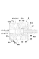
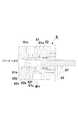
図1は、本発明に係るオイルバーナー用燃料調節弁の一実施例の軸方向に沿った断面図、
図2は、図1に示すオイルバーナー用燃料調節弁を、その開度目盛板の方向から見た外観図、
図3は、図1に示すオイルバーナー用燃料調節弁に収容されている弁体の外観図、
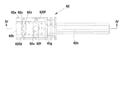
図4は、図3中のIV−IV線に沿った断面図、
図5は、図4中のV−V線に沿った断面図、
図6は、図4中のVI−VI線に沿った断面図、
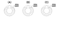
図7は、弁体の側壁外面に形成される燃料流入溝及び燃料戻り溝の底部の輪郭線の各種形態を示す断面図、
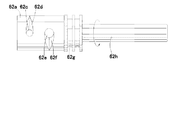
図8は、弁体の側壁外面に形成される燃料流入溝及び燃料戻り溝のもう一つの実施例を示す外観図、
図9は、弁本体の内周面の弁座の各種形態を示す断面図、
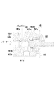
図10は、図1に示すオイルバーナー用燃料調節弁の機能(低燃焼時のバイパス戻油の状態)を説明するための断面図、
図11は、図1に示すオイルバーナー用燃料調節弁の機能(高燃焼時のバイパス送油の状態)を説明するための断面図、
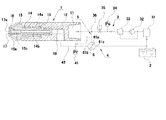
図12は、本発明に係るオイルバーナー用燃料供給装置の一実施例を、その低燃焼時(バイパス戻油時)における燃料油の流れと共に示す説明図、
図13は、高燃焼時(バイパス送油時)における燃料油の流れを示す図12と同様の説明図、
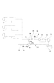
図14は、本発明に係るオイルバーナー用燃料供給装置のもう一つの実施例を示す説明図、
図15は、本発明に係るオイルバーナー用燃料調節弁の開度とバイパスノズルへ供給される燃料オイルの流量の関係の一例を示すグラフである。
FIG. 1 is a sectional view along an axial direction of an embodiment of a fuel control valve for an oil burner according to the present invention,
FIG. 2 is an external view of the fuel control valve for an oil burner shown in FIG. 1 as viewed from the direction of the opening scale plate.
FIG. 3 is an external view of a valve body housed in the fuel control valve for an oil burner shown in FIG.
4 is a cross-sectional view taken along line IV-IV in FIG.
FIG. 5 is a cross-sectional view taken along line VV in FIG.
6 is a sectional view taken along line VI-VI in FIG.
FIG. 7 is a cross-sectional view showing various forms of the contour lines of the bottom of the fuel inflow groove and the fuel return groove formed on the outer surface of the side wall of the valve body
FIG. 8 is an external view showing another embodiment of the fuel inflow groove and the fuel return groove formed on the outer surface of the side wall of the valve body,
FIG. 9 is a cross-sectional view showing various forms of the valve seat on the inner peripheral surface of the valve body,
FIG. 10 is a cross-sectional view for explaining the function (state of bypass return oil at low combustion) of the fuel control valve for the oil burner shown in FIG.
FIG. 11 is a cross-sectional view for explaining the function (state of bypass oil feeding during high combustion) of the fuel control valve for the oil burner shown in FIG.
FIG. 12 is an explanatory diagram showing an embodiment of a fuel supply device for an oil burner according to the present invention, together with the flow of fuel oil at the time of low combustion (at the time of bypass return oil),
FIG. 13 is an explanatory view similar to FIG. 12 showing the flow of fuel oil at the time of high combustion (at the time of bypass oil feeding),
FIG. 14 is an explanatory view showing another embodiment of the fuel supply device for an oil burner according to the present invention,
FIG. 15 is a graph showing an example of the relationship between the opening of the fuel control valve for an oil burner according to the present invention and the flow rate of the fuel oil supplied to the bypass nozzle.
まず、図1〜図11を参照しつつ、本発明に係るオイルバーナー用燃料調節弁6の構成について説明する。
これらの図中、61は弁本体、62は弁体、63はOリング、64はシャフトホルダ、65は開度目盛板、66は固定ネジ、67は開度指針である。
また、弁本体61において、61aは燃料供給管接続部、61bは燃料バイパス管接続部、61cは燃料戻り管接続部、61dは回転シャフト挿通部、61eは弁室であり、また、弁体62において、62aは円筒部、62bは円筒部の内部、62cは燃料流入孔、62dは燃料流入溝、62eは燃料戻り孔、62fは燃料戻り溝、62gはOリング装着溝、62hは回転シャフトである。
First, the structure of the oil burner
In these drawings, 61 is a valve body, 62 is a valve body, 63 is an O-ring, 64 is a shaft holder, 65 is an opening scale plate, 66 is a fixing screw, and 67 is an opening pointer.
In the valve
図1に示す如く、弁本体61の左端部には、オイルバーナーのバイパスノズル1(図12参照)のリターンオイル出口18(図12参照)へ通じる燃料バイパス管43(図12参照)を取り付けるための燃料バイパス管接続部61bが設けられ、右端部には、シャフトホルダ64が取り付けられ、その回転シャフト挿通部61dに、弁体62の回転シャフト62hが挿通され、回転自在に保持されるようになっている。弁本体61の内部には、弁体62の円筒部62aを回転自在に収容する弁室61eが設けられ、弁本体61の側壁には、弁室61eに通じる燃料供給管接続部61aと、燃料戻り管接続部61cとが設けられている。この燃料供給管接続部61aの弁室側開口周縁部は、燃料供給管路用弁座610aとして機能し、同様に、燃料戻り管接続部61cの弁室側開口周縁部は、戻り管路用弁座610cとして機能するように構成されている。
As shown in FIG. 1, a fuel bypass pipe 43 (see FIG. 12) leading to the return oil outlet 18 (see FIG. 12) of the bypass nozzle 1 (see FIG. 12) of the oil burner is attached to the left end portion of the
一方、弁体62は、図1、図3〜図6に示す如く、左端側が解放され右端側が閉鎖された円筒部62aと、その閉鎖端に一体的に設けられた操作用の回転シャフト62hとから構成され、円筒部62aと回転シャフト62hとの間には、Oリング装着溝62gが形成されている。円筒部62aの側壁には、その内部62bに通じる燃料流入孔62cと燃料戻り孔62eとが明けられている。この燃料流入孔62cは、図1に示す如く、弁本体61の燃料供給管接続部61aに対応する位置に明けられ、また、燃料戻り孔62eは、燃料戻り管接続部61cに対応する位置に明けられている。なお、図示した実施例においては、燃料流入孔62cと燃料戻り孔62eは軸方向に同一位置に並べて、即ち、弁体の中心軸を含む一平面上に並べて配置されている。
更にまた、弁体62の側壁外面において燃料流入孔62c及び燃料戻り孔62eに隣接する領域には、円周方向に沿って、それぞれ燃料流入孔62c及び燃料戻り孔62eに通じ、かつそれぞれ当該燃料流入孔62c及び燃料戻り孔62eの中心軸から離れるにつれて溝横断面積が順次減少するように構成された燃料流入溝62d及び燃料戻り溝62fが形成されている。これらの燃料流入溝62d及び燃料戻り溝62fが、弁本体61内での弁体62の回転角度位置に応じて、燃料流入孔62c及び燃料戻り孔62eを通過する燃料オイルの流量を増減、調節する役割を果たすようになっている。
On the other hand, as shown in FIGS. 1 and 3 to 6, the
Furthermore, the region adjacent to the
次に、このオイルバーナー用燃料調節弁6の機能を、図10及び図11を参照しつつ説明する。
弁体62の回転シャフト62hを回動操作して、弁本体61の弁室61e内での弁体62の円筒部62aの回転角度位置を調整し、図10に示す如く、弁体62の燃料流入孔62c及び燃料戻り孔62eが真下を向くような状態にすると、燃料流入孔62cと燃料流入溝62dは弁室61eの内壁面により閉鎖(弁本体61の燃料供給管接続部61aから弁体62の燃料流入孔62cへの流路は遮断)される。このとき、弁体62の燃料戻り孔62eの中心軸は、弁本体61の燃料戻り管接続部61cの中心軸と一致し、弁本体61の燃料バイパス管接続部61bから弁本体61の燃料戻り管接続部61cへ通じる流路は全開状態(即ち、弁の全開状態)となる。従って、燃料バイパス管接続部61bに、バーナーのバイパスノズルのリターンオイル出口からの戻り油を導入すれば、当該戻り油は、弁体の内部62bから燃料戻り孔62e及び燃料戻り管接続部61cを通じて、燃料戻り管路へ導かれ、燃料タンクへ回収されることになる。
ここで、図10に示した状態から、弁体62の回転シャフト62hを若干回動させると、燃料戻り孔62eの中心軸と弁本体61の燃料戻り管接続部61cの中心軸との一致状態は損なわれるが、燃料オイルは燃料戻り孔62eの周囲の前記燃料戻り溝62fを通じて燃料戻り孔62eへ流入し、上記と同様に弁本体61の燃料戻り管接続部61cを通じて燃料戻り管路へ導かれ、燃料タンクへ回収される。このときの流量は、上記全開状態のときよりも少なく、燃料戻り溝62fと燃料戻り管接続部61cとの相対位置関係によって決定される。即ち、燃料戻り溝62fの断面積は、燃料戻り孔62eの中心軸から離れるにつれて次第に減少するように形成されているので、弁体62の回転シャフト62hによる回転角度位置に応じて、燃料戻り溝62fによる弁開度の調節が行われることになる。
Next, the function of the oil burner
The
Here, when the
次に、上記と同様に、弁体62の回転シャフト62hを回動操作して、弁本体61の弁室61e内での弁体62の円筒部62aの回転角度位置を調整し、図11に示す如く、弁体62の燃料流入孔62c及び燃料戻り孔62eが真上を向くような状態にすると、燃料戻り孔62eと燃料戻り溝62fは弁室61eの内壁面により閉鎖(弁体62の燃料戻り孔62eから弁本体61の燃料戻り管接続部61cへの流路は遮断)される。このとき、弁体62の燃料流入孔62cの中心軸は、弁本体61の燃料供給管接続部61aの中心軸と一致し、弁本体61の燃料供給管接続部61aから弁本体61の燃料バイパス管接続部61bへ通じる流路は全開状態(即ち、弁の全開状態)となる。従って、燃料供給管接続部61aに、ポンプから送り出される燃料オイルを導入すれば、当該燃料オイルは、弁体の内部62bから燃料バイパス管接続部61bを通じてバイパスノズルへ送り出され、燃焼されることになる。
この場合も、図11に示した状態から、弁体62の回転シャフト62hを若干回動させると、燃料流入孔62cの中心軸と弁本体61の燃料供給管接続部61aの中心軸との一致状態は損なわれるが、燃料オイルは燃料流入孔62cの周囲の前記燃料流入溝62dを通じて燃料流入孔62cへ流入し、上記と同様に弁本体61の燃料バイパス管接続部61bを通じてバイパスノズルへ送り出され、燃焼される。このときの流量も、上記全開状態のときよりも少なく、燃料流入溝62dと燃料供給管接続部61aとの相対位置関係によって決定されるので、弁体62の回転シャフト62hによる回転角度位置に応じて、燃料流入溝62dによる弁開度の調節が行われることになる。
Next, similarly to the above, the
Also in this case, when the
なお、弁体62の円筒部の外周面に形成される燃料流入溝62dや燃料戻り溝62fの横断面積は、上記の如く流量調整を可能とするために、燃料流入孔62cや燃料戻り孔62eの中心軸から離れるにつれて次第に減少するように形成されているが、この場合において、弁体の回転角度と流量の関係を、正比例その他単純な関数となるようにするために、燃料流入溝62d及び燃料戻り溝62fを何れもV溝として形成すると共に、図7に示すように、弁体62の軸直角断面における当該V溝の底部の輪郭線620d(又は620f)を、図7(a)の如く、弁体外径の半径より大きな曲率半径を有する曲線としたり、或いはまた、同(b)の如く直線としたり、同(c)の如く直線の組合せとしたりすることも推奨される。
また、同様の理由で、弁体の燃料流入溝62d又は燃料戻り溝62fと共働して流量を決定することになる弁座、即ち、弁本体61側の燃料供給管接続部61aの弁室側開口周縁部610a、及び、燃料戻り管接続部61cの弁室側開口周縁部610cの形状を、図9(A)に示す如く円形としたり、同(B)に示す如く四角形としたり、同(C)に示す如く三角形としたりすることも考えられる。
また、弁体62の図3に示した実施例では、燃料流入孔62cの両側に燃料流入溝62dを設け、同じく、燃料戻り孔62eの両側に燃料戻り溝62fを設けたが、図8に示すように、燃料流入孔62cや燃料戻り孔62eの片側にだけ燃料流入溝62dや燃料戻り溝62fを設けるようにしても、本発明の目的を達成できる。
Note that the cross-sectional area of the
For the same reason, the valve seat that determines the flow rate in cooperation with the
Further, in the embodiment shown in FIG. 3 of the
次に、上記の如き構成及び機能を有する本発明に係る燃料調節弁6を用いたオイルバーナー用燃料供給装置について、図12及び図13を参照しつつ説明する。
このオイルバーナー用燃料供給装置が、特許文献1に記載の図16及び図17の燃料供給装置と異なる点は、図16及び図17の燃料供給装置では2個の流量制御弁A及びBを用いていたのに対し、図12及び図13の燃料供給装置では、本発明に係る1個の流量制御弁6を用いて同様の機能を達成しているという点である。
Next, an oil burner fuel supply device using the
The fuel supply device for oil burner is different from the fuel supply device shown in FIGS. 16 and 17 described in
図12及び図13中、1はバイパスノズルアッシィ、2は燃料タンク、3は燃料供給管路、4は燃料戻り管路、43は燃料バイパス管、5は第二の燃料供給管路である。
バイパスノズルアッシィ1において、11はオイル入口、12はオイルの流路、13はストレーナ、14は中空ピン、14aはストレーナ13と中空ピン14の間に形成される環状流路、14bはバイパス路、15はディストリビューター、15aは螺旋溝、15bはバイパス路、16は渦室、17はオリフィス部材、17aは噴口、18はリターンオイル出口である。
燃料供給管路3には、フィルタ31、ポンプ32、レリーフバルブ33、供給圧測定用圧力計34、電磁弁35等が設けられている。燃料バイパス管43には、戻り油圧測定用圧力計41が設けられている。
12 and 13, 1 is a bypass nozzle assembly, 2 is a fuel tank, 3 is a fuel supply line, 4 is a fuel return line, 43 is a fuel bypass line, and 5 is a second fuel supply line. .
In the
The
本発明に係る燃料調節弁6の前記燃料供給管接続部61aは、燃料供給管路3の燃料供給ポンプ32のデリバリ側の分岐部36から分岐する第二の燃料供給管路5に接続され、また、燃料バイパス管接続部61bは燃料バイパス管43に接続され、燃料戻り管接続部61cは燃料戻り管路4に接続されている。
The fuel supply
先ず、図12に示す低燃焼時(バイパス戻油時)には、燃料調節弁6は図10に示すような作動状態、即ち、バイパスノズルアッシィ1のリターンオイル出口18から排出され、燃料バイパス管43及び燃料バイパス管接続部61bを通じて導入される戻り油を、燃料戻り管接続部61cを通じて燃料戻り管路4に導く状態となっている。
バイパスノズルアッシィ1のオイル入口11から送り込まれた燃料油は、前記と同様に、流路12からストレーナ13及び環状流路14aを経て、ディストリビューター15の外周壁に形成した螺旋溝15aを通じて渦室16内へ導入される。渦室16内で渦流となった燃料油の一部は、オリフィス部材17の噴口17aから噴射、燃焼されると共に、残りの燃料油は、ディストリビューター15のバイパス路15b及び中空ピン14のバイパス路14bを通じてリターンオイル出口18から排出され、燃料バイパス管43を通じて燃料調節弁6の燃料バイパス管接続部61bから弁の内部62bを通過し、燃料戻り管接続部61cから燃料戻り管路4を通じて燃料タンク2に還流する。
このとき、弁体62の回転シャフト62hの回転角度位置を調整することにより、弁の開度を全開状態から全閉状態までの間で連続的に変化させることにより燃焼量を連続的に増減させことが可能となる。
この場合の燃焼状態は、図16で説明したのと同様である。
First, at the time of low combustion shown in FIG. 12 (at the time of bypass return oil), the
The fuel oil fed from the oil inlet 11 of the
At this time, by adjusting the rotational angle position of the
The combustion state in this case is the same as described in FIG.
次に、図13に示す高燃焼時(バイパス送油時)には、燃料調節弁6は図11に示すような作動状態、即ち、第二の燃料供給管路5から燃料供給管接続部61aを通じて弁の内部62bに導入された燃料オイルは、燃料バイパス管接続部61bから燃料バイパス管43を通じてバイパスノズルのリターンオイル出口18へ送り込まれ、ノズル内のバイパス路14b及び15bを経て、渦室16へ送られ、流路12を通じてノズル内へ導入された燃料オイルと共に噴口17aから噴射され、図17の場合と同様に燃焼されるものである。
この場合も、弁体62の回転シャフト62hの回転角度位置を調整することにより、弁の開度を全閉状態から全開状態までの間で連続的に変化させることにより燃焼量を連続的に増減させことが可能となる。
Next, at the time of high combustion shown in FIG. 13 (at the time of bypass oil feeding), the
Also in this case, by adjusting the rotational angle position of the
図14は、本発明に係る燃料供給装置の他の一例として、複数本のノズルアッシー1を並列に接続し、同時に噴射を行う実施例を示している。
また、図15は、本発明に係るオイルバーナー用燃料調節弁の開度とバイパスノズルへ供給される燃料オイルの流量の関係の一例を示すグラフであり、低燃焼レベルから高燃焼レベルまで連続的に増減制御でき、ターンダウン比を1:8以上にすることが可能であることを示している。
FIG. 14 shows an embodiment in which a plurality of
FIG. 15 is a graph showing an example of the relationship between the opening degree of the fuel control valve for an oil burner according to the present invention and the flow rate of the fuel oil supplied to the bypass nozzle, which is continuously from a low combustion level to a high combustion level. This indicates that the increase / decrease control can be performed and the turndown ratio can be 1: 8 or more.
なお、本発明は上記の実施例に限定されるものではなく、その目的の範囲内において、上記の説明から当業者が容易に想到し得るすべての変更実施例を包摂するものである。 The present invention is not limited to the above-described embodiments, and includes all modified embodiments that can be easily conceived by those skilled in the art from the above description within the scope of the object.
本発明は上記の如く構成されるから、本発明によるときは、単一の流量制御弁で前記特許文献1に記載の燃料供給装置と同様の作用効果を達成し得るオイルバーナー用燃料調節弁、及び、当該燃料調節弁を用いたオイルバーナー用燃料供給装置を提供し得るものであり、これにより、操作若しくは制御の容易化及びコストの低減化を図ることが可能となるので産業上多大の利用可能性を有するものである。
Since the present invention is configured as described above, according to the present invention, a fuel control valve for an oil burner that can achieve the same effect as the fuel supply device described in
1 バイパスノズルアッシィ
11 オイル入口
12 流路
13 ストレーナ
14 中空ピン
14a 環状流路
14b バイパス路
15 ディストリビューター
15a らせん溝
15b バイパス路
16 渦室
17 オリフィス部材
17a 噴口
18 リターンオイル出口
2 燃料タンク
3 燃料供給管路
31 フィルタ
32 ポンプ
33 レリーフバルブ
34 供給圧測定用圧力計
35 電磁弁
36 分岐部
4 燃料戻り管路
41 戻り油圧測定用圧力計
43 燃料バイパス管
5 第二の燃料供給管路
6 本発明のオイルバーナー用燃料調節弁(流量制御弁)
61 弁本体
61a 燃料供給管接続部
61b 燃料バイパス管接続部
61c 燃料戻り管接続部
61d 回転シャフト挿通部
61e 弁室
62 弁体
62a 円筒部
62b 円筒部の内部
62c 燃料流入孔
62d 燃料流入溝
62e 燃料戻り孔
62f 燃料戻り溝
62g Oリング装着溝
62h 回転シャフト
63 Oリング
64 シャフトホルダ
65 開度目盛板
66 固定ネジ
67 開度指針
A 流量制御弁
B 第二の流量制御弁
101 バイパスノズルアッシィ
102 燃料タンク
103 燃料供給管路
104 燃料戻り管路
105 第二の燃料供給管路
111 オイル入口
112 流路
113 ストレーナ
114 中空ピン
114a 環状流路
114b バイパス路
115 ディストリビューター
115a らせん溝
115b バイパス路
116 渦室
117 オリフィス部材
117a 噴口
118 リターンオイル出口
131 フィルタ
132 ポンプ
133 レリーフバルブ
134 供給圧測定用圧力計
135 電磁弁
136 分岐部
141 戻り油圧測定用圧力計
DESCRIPTION OF
61
Claims (8)
一端部には、バイパスノズル(1)のリターンオイル出口(18)へ通じる燃料バイパス管(43)を取り付けるための燃料バイパス管接続部(61b)が設けられ、他の一端部には、弁体の回転シャフト挿通部(61d)が設けられ、内部に上記弁体(62)の円筒部(62a)を回転自在に収容する弁室(61e)を有し、側壁にはそれぞれ弁室に通じる燃料供給管接続部(61a)と、燃料戻り管接続部(61c)とが設けられ、燃料供給管接続部(61a)及び燃料戻り管接続部(61c)の弁室側開口周縁部は、それぞれ燃料供給管路用弁座(610a)及び戻り管路用弁座(610c)として機能するよう構成された弁本体(61)と;
を具備する流量制御弁(6)であって;
弁体(62)の燃料流入孔(62c)及び燃料戻り孔(62e)はそれぞれ、弁本体(61)の燃料供給管接続部(61a)と、燃料戻り管接続部(61c)に通じ得る位置に設けられ;
弁体(62)の側壁外面には、円周方向に沿って、それぞれ燃料流入孔(62c)及び燃料戻り孔(62e)に通じ、かつそれぞれ当該燃料流入孔及び燃料戻り孔の中心軸から離れるにつれて溝横断面積が順次減少するよう構成された燃料流入溝(62d)及び燃料戻り溝(62f)が、円周方向に沿って設けられ;
弁本体(61)の弁室(61e)内での弁体(62)の円筒部(62a)の回転角度位置に応じて、弁体(62)の燃料流入溝(62d)が弁室(61e)の内壁面により閉鎖されている間は、弁体(62)の燃料戻り溝(62f)を通じて弁体(62)の燃料戻り孔(62e)が弁本体(61)の燃料戻り管接続部(61c)に連通し、これにより、バイパスノズル(1)から燃料戻り管路(4)への弁が開かれると共に、当該燃料戻り溝(62f)による弁開度の調節が行われ、他方、弁体(62)の燃料戻り溝(62f)が弁室(61e)の内壁面により閉鎖されている間は、弁体(62)の燃料流入溝(62d)を通じて弁体(62)の燃料流入孔(62c)が弁本体(61)の燃料供給管接続部(61a)に連通し、これにより、燃料供給管路(5)からバイパスノズル(1)への弁が開かれると共に、当該燃料流入溝(62d)による弁開度の調節が行われるよう構成されたこと;
を特徴とするオイルバーナー用燃料調節弁(6)。 A rotating shaft (62h) for operation is provided at the closed end of the cylindrical portion (62a) whose one end is released and the other end is closed, and a fuel inflow hole leading to the inside (62b) is provided on the side wall of the cylindrical portion (62a). (62c) and a valve body (62) with a fuel return hole (62e) opened;
A fuel bypass pipe connection part (61b) for attaching a fuel bypass pipe (43) leading to the return oil outlet (18) of the bypass nozzle (1) is provided at one end part, and a valve body is provided at the other end part. The rotary shaft insertion portion (61d) is provided, and has a valve chamber (61e) in which the cylindrical portion (62a) of the valve body (62) is rotatably accommodated, and fuel that communicates with the valve chamber on each side wall A supply pipe connection part (61a) and a fuel return pipe connection part (61c) are provided, and the valve chamber side opening peripheral parts of the fuel supply pipe connection part (61a) and the fuel return pipe connection part (61c) A valve body (61) configured to function as a supply line valve seat (610a) and a return line valve seat (610c);
A flow control valve (6) comprising:
The fuel inflow hole (62c) and the fuel return hole (62e) of the valve body (62) can communicate with the fuel supply pipe connection part (61a) and the fuel return pipe connection part (61c) of the valve body (61), respectively. Provided in;
The outer surface of the side wall of the valve body (62) communicates with the fuel inflow hole (62c) and the fuel return hole (62e) along the circumferential direction, and is separated from the center axis of the fuel inflow hole and the fuel return hole, respectively. A fuel inflow groove (62d) and a fuel return groove (62f) configured to sequentially decrease the groove cross-sectional area as the groove cross-sectional area is provided along the circumferential direction;
Depending on the rotational angle position of the cylindrical part (62a) of the valve body (62) in the valve chamber (61e) of the valve body (61), the fuel inflow groove (62d) of the valve body (62) is formed in the valve chamber (61e). ) Is closed by the fuel return groove (62f) of the valve body (62), the fuel return hole (62e) of the valve body (62) is connected to the fuel return pipe connecting portion ( 61c), thereby opening the valve from the bypass nozzle (1) to the fuel return line (4) and adjusting the valve opening by the fuel return groove (62f), While the fuel return groove (62f) of the body (62) is closed by the inner wall surface of the valve chamber (61e), the fuel inflow hole of the valve body (62) through the fuel inflow groove (62d) of the valve body (62). (62c) communicates with the fuel supply pipe connection (61a) of the valve body (61), thereby Charge supply line (5) together with the valve to the bypass nozzle (1) is opened from the adjustment of the valve opening by the fuel inflow groove (62d) is configured to be performed;
A fuel control valve for an oil burner (6) characterized by
請求項1ないし5のいずれか一項に記載のオイルバーナー用燃料調節弁(6)の弁本体(61)の燃料供給管接続部(61a)を上記第二の燃料供給管路(5)に接続し、燃料バイパス管接続部(61b)を上記燃料バイパス管(43)に接続し、燃料戻り管接続部(61c)を上記燃料戻り管路(4)に接続し;
弁体(62)の前記回転シャフト(62h)の回転角度位置を調整することにより、低燃焼レベルにおいては、弁体(62)の燃料流入溝(62d)を弁室(61e)の内壁面により閉鎖し、弁体(62)の燃料戻り溝(62f)を通じて弁体(62)の燃料戻り孔(62e)を弁本体(61)の燃料戻り管接続部(61c)と連通させ、これにより、バイパスノズル(1)から燃料バイパス管(43)を介して燃料戻り管路(4)へ通じる流路の弁が開かれるよう操作すると共に、当該弁の開度を前記回転シャフト(62h)の回転角度位置を調整して全開状態から全閉状態までの間で連続的に変化させることにより燃焼量を連続的に増減させ;
それより更に高燃焼レベルにおいては、上記と同様に弁体(62)の回転シャフト(62h)の回転角度位置を調整することにより、弁体(62)の燃料戻り溝(62f)を弁室(61e)の内壁面により閉鎖し、弁体(62)の燃料流入溝(62d)を通じて弁体(62)の燃料流入孔(62c)を弁本体(61)の燃料供給管接続部(61a)と連通させ、これにより、第二の燃料供給管路(5)からバイパスノズル(1)へ通じる流路の弁が開かれるよう操作すると共に、当該弁の開度を前記回転シャフト(62h)の回転角度位置を調整して全閉状態から全開状態までの間で連続的に変化させることにより燃焼量を連続的に増減させ得るよう構成したこと;
を特徴とするオイルバーナー用燃料供給装置。 Fuel connected to the fuel supply line (3) for supplying fuel oil from the fuel tank (2) to the bypass nozzle (1) by the fuel supply pump (32) and the return oil outlet (18) of the bypass nozzle (1) Provided in the fuel return line (4) for returning the fuel oil partially recirculated through the bypass pipe (43) to the fuel tank (2) and the fuel supply line (3) on the delivery side of the fuel supply pump (32) A second fuel supply line (5) for supplying fuel oil from the branched portion (36) to the return oil outlet (18) of the bypass nozzle (1) through the fuel bypass pipe (43);
The fuel supply pipe connection (61a) of the valve body (61) of the fuel control valve (6) for an oil burner according to any one of claims 1 to 5 is connected to the second fuel supply pipe (5). Connecting, connecting the fuel bypass pipe connection (61b) to the fuel bypass pipe (43), and connecting the fuel return pipe connection (61c) to the fuel return pipe (4);
By adjusting the rotational angle position of the rotary shaft (62h) of the valve body (62), the fuel inflow groove (62d) of the valve body (62) is made to be formed by the inner wall surface of the valve chamber (61e) at a low combustion level. The fuel return hole (62e) of the valve body (62) is communicated with the fuel return pipe connection (61c) of the valve body (61) through the fuel return groove (62f) of the valve body (62). The valve of the flow path leading from the bypass nozzle (1) to the fuel return pipe (4) through the fuel bypass pipe (43) is opened, and the opening degree of the valve is adjusted to rotate the rotary shaft (62h). Continuously increasing or decreasing the amount of combustion by adjusting the angular position and continuously changing from fully open to fully closed;
At a higher combustion level than that, the fuel return groove (62f) of the valve body (62) is formed in the valve chamber (62f) by adjusting the rotational angle position of the rotary shaft (62h) of the valve body (62) in the same manner as described above. 61e) is closed by the inner wall surface, and the fuel inflow hole (62c) of the valve body (62) is connected to the fuel supply pipe connection part (61a) of the valve body (61) through the fuel inflow groove (62d) of the valve body (62). In this way, the valve of the flow path leading from the second fuel supply pipe (5) to the bypass nozzle (1) is opened, and the opening degree of the valve is rotated by the rotation shaft (62h). It is configured so that the combustion amount can be increased or decreased continuously by adjusting the angular position and continuously changing from the fully closed state to the fully open state;
A fuel supply device for an oil burner.
Priority Applications (1)
| Application Number | Priority Date | Filing Date | Title |
|---|---|---|---|
| JP2004103667A JP4294529B2 (en) | 2004-03-31 | 2004-03-31 | Oil control valve for oil burner and fuel supply device for oil burner using the valve |
Applications Claiming Priority (1)
| Application Number | Priority Date | Filing Date | Title |
|---|---|---|---|
| JP2004103667A JP4294529B2 (en) | 2004-03-31 | 2004-03-31 | Oil control valve for oil burner and fuel supply device for oil burner using the valve |
Publications (2)
| Publication Number | Publication Date |
|---|---|
| JP2005291545A true JP2005291545A (en) | 2005-10-20 |
| JP4294529B2 JP4294529B2 (en) | 2009-07-15 |
Family
ID=35324673
Family Applications (1)
| Application Number | Title | Priority Date | Filing Date |
|---|---|---|---|
| JP2004103667A Expired - Fee Related JP4294529B2 (en) | 2004-03-31 | 2004-03-31 | Oil control valve for oil burner and fuel supply device for oil burner using the valve |
Country Status (1)
| Country | Link |
|---|---|
| JP (1) | JP4294529B2 (en) |
Cited By (2)
| Publication number | Priority date | Publication date | Assignee | Title |
|---|---|---|---|---|
| CN110985585A (en) * | 2019-12-17 | 2020-04-10 | 浙江工业大学 | Damper Control Valve and Hydraulic Damper |
| CN114850144A (en) * | 2022-04-28 | 2022-08-05 | 南通海狮船舶机械有限公司 | A kind of ship pipeline flushing pulse generator |
-
2004
- 2004-03-31 JP JP2004103667A patent/JP4294529B2/en not_active Expired - Fee Related
Cited By (2)
| Publication number | Priority date | Publication date | Assignee | Title |
|---|---|---|---|---|
| CN110985585A (en) * | 2019-12-17 | 2020-04-10 | 浙江工业大学 | Damper Control Valve and Hydraulic Damper |
| CN114850144A (en) * | 2022-04-28 | 2022-08-05 | 南通海狮船舶机械有限公司 | A kind of ship pipeline flushing pulse generator |
Also Published As
| Publication number | Publication date |
|---|---|
| JP4294529B2 (en) | 2009-07-15 |
Similar Documents
| Publication | Publication Date | Title |
|---|---|---|
| EP2072780B1 (en) | A fuel distribution apparatus | |
| US20100126431A1 (en) | Combustion apparatus | |
| US8196897B2 (en) | Device for distributing gas to a cooking appliance | |
| US5611684A (en) | Fuel-air mixing unit | |
| US6050809A (en) | Immersion tube burner with improved flame stability | |
| US7011101B2 (en) | Valve system | |
| JP4294529B2 (en) | Oil control valve for oil burner and fuel supply device for oil burner using the valve | |
| JP2010127577A (en) | Combustion apparatus | |
| US1396086A (en) | Fuel-oil burner | |
| US9188334B2 (en) | Dual fuel heater | |
| EP0077786B1 (en) | Liquid fuel burner | |
| JP7069895B2 (en) | A multi-way valve and a fluid control device including the multi-way valve | |
| US4960377A (en) | Gas/air mixing valve | |
| JP6715624B2 (en) | Gas burner | |
| US2506313A (en) | Combined filter and valve for gaseous fuel | |
| US9915427B2 (en) | Dual fuel pilot light burner | |
| SE459364B (en) | FOERBRAENNINGSANORDNING | |
| JP7056270B2 (en) | Combustion device | |
| CN219673428U (en) | Valve core, change-over switch and generator | |
| US1699297A (en) | Device for controlling fuel supply to gas-burner pilots | |
| US12478987B2 (en) | 3-D printed variable pattern nozzle | |
| JP2000055346A (en) | Fuel supply device for oil fired burner | |
| JPS6216199Y2 (en) | ||
| KR101977423B1 (en) | Fuel valve | |
| US20210388984A1 (en) | Single inlet oxygen burner for metal making |
Legal Events
| Date | Code | Title | Description |
|---|---|---|---|
| A621 | Written request for application examination |
Free format text: JAPANESE INTERMEDIATE CODE: A621 Effective date: 20070326 |
|
| A977 | Report on retrieval |
Free format text: JAPANESE INTERMEDIATE CODE: A971007 Effective date: 20090122 |
|
| TRDD | Decision of grant or rejection written | ||
| A01 | Written decision to grant a patent or to grant a registration (utility model) |
Free format text: JAPANESE INTERMEDIATE CODE: A01 Effective date: 20090402 |
|
| A01 | Written decision to grant a patent or to grant a registration (utility model) |
Free format text: JAPANESE INTERMEDIATE CODE: A01 |
|
| A61 | First payment of annual fees (during grant procedure) |
Free format text: JAPANESE INTERMEDIATE CODE: A61 Effective date: 20090408 |
|
| FPAY | Renewal fee payment (prs date is renewal date of database) |
Free format text: PAYMENT UNTIL: 20120417 Year of fee payment: 3 |
|
| R150 | Certificate of patent (=grant) or registration of utility model |
Free format text: JAPANESE INTERMEDIATE CODE: R150 |
|
| FPAY | Renewal fee payment (prs date is renewal date of database) |
Free format text: PAYMENT UNTIL: 20130417 Year of fee payment: 4 |
|
| FPAY | Renewal fee payment (prs date is renewal date of database) |
Free format text: PAYMENT UNTIL: 20130417 Year of fee payment: 4 |
|
| FPAY | Renewal fee payment (prs date is renewal date of database) |
Free format text: PAYMENT UNTIL: 20140417 Year of fee payment: 5 |
|
| LAPS | Cancellation because of no payment of annual fees |