JP2005291534A - Combustion equipment and method of biomass fuel - Google Patents
Combustion equipment and method of biomass fuel Download PDFInfo
- Publication number
- JP2005291534A JP2005291534A JP2004103275A JP2004103275A JP2005291534A JP 2005291534 A JP2005291534 A JP 2005291534A JP 2004103275 A JP2004103275 A JP 2004103275A JP 2004103275 A JP2004103275 A JP 2004103275A JP 2005291534 A JP2005291534 A JP 2005291534A
- Authority
- JP
- Japan
- Prior art keywords
- biomass fuel
- combustion
- fuel
- nozzle
- pulverized coal
- Prior art date
- Legal status (The legal status is an assumption and is not a legal conclusion. Google has not performed a legal analysis and makes no representation as to the accuracy of the status listed.)
- Granted
Links
Images


Abstract
Description
本発明は石炭焚きの燃焼装置において、バイオマス燃料を補助燃料として利用することで、燃焼排ガスの低NOx化と高効率燃焼を達成させ、CO2排出量を削減する技術に関する。 TECHNICAL FIELD The present invention relates to a technique for reducing CO 2 emissions by using a biomass fuel as an auxiliary fuel to achieve low NOx and high-efficiency combustion of combustion exhaust gas in a coal burning combustion apparatus.
本発明でいうバイオマス燃料とは化石燃料以外の植物系燃料であり、その種類を特定のものに限定するものではないが、特に森林や生活リサイクルとして出てくる全ての廃材や汚泥、さらにその二次加工製品等を含む燃料となりうる発熱量を有する植物系燃料をいうものとする。 Biomass fuel as used in the present invention is a plant-based fuel other than fossil fuels, and the type thereof is not limited to a specific one. It shall mean a plant-based fuel having a calorific value that can be a fuel containing a next processed product.
近年、化石燃料を主燃料として燃焼するボイラでのCO2排出量の削減策の1つとして木質系バイオマスの混焼技術が注目されている。 In recent years, wood-based biomass co-firing technology has attracted attention as one of the measures for reducing CO 2 emissions in boilers that use fossil fuel as the main fuel.
特に欧州、北米では木質系バイオマス燃料を既設の石炭微粉砕機に混合・投入して混合粉砕した後、微粉炭と共に石炭焚きボイラ火炉内に供給して燃焼させることが多く行われている。木質系バイオマス燃料としては、ボイラの立地場所に運搬される以前に、予め微粉砕して、いわゆるペレット化したものや、粒径が50mmアンダー程度に粉砕された木質チップ状にしたものが流通している。その他の木質系バイオマス燃料と石炭の混焼の例としては、木質系バイオマス燃料を専用の粉砕機で微粉砕した後、微粉炭の搬送ラインに供給することにより両者を混合して火炉内で混焼させる技術も多く行われている。
前述したように木質系バイオマス燃料をペレット化する場合には、木質系バイオマス燃料を微粉砕してペレットを製造するが、この過程では非常に大きい粉砕動力が必要となる。通常の石炭焚き火力で使用される石炭に要する粉砕動力と比較すると、木質系バイオマス燃料で同じ粒度を得るために10倍以上の動力が必要であることが知られている。例えば石炭では、ローラミルを粉砕機として使用した場合、10〜20kWh/tであるのに対して、バイオマス燃料をインパクトミル(バイオマス燃料の粉砕に最も多く使用されている)を粉砕機として使用した場合、動力は通常100〜200kwh/tとなる。ただしバイオマス燃料は同じ粒径であれば石炭よりも燃えやすいため、微粉炭に比べて粉砕粒径を粗くできる。すなわちバイオマス燃料の粉砕では燃焼可能な限界まで粉砕粒径を粗くするのが運用上好ましい。 As described above, when pelletizing the woody biomass fuel, the woody biomass fuel is finely pulverized to produce pellets. In this process, very large pulverization power is required. Compared with the pulverization power required for coal used in ordinary coal-fired thermal power, it is known that 10 times or more power is required to obtain the same particle size with woody biomass fuel. For example, in coal, when a roller mill is used as a pulverizer, it is 10 to 20 kWh / t, whereas when biomass fuel is used as an impact mill (used most for pulverizing biomass fuel) as a pulverizer The power is normally 100 to 200 kwh / t. However, since biomass fuel is easier to burn than coal if the particle size is the same, the pulverized particle size can be made coarser than pulverized coal. That is, in the pulverization of biomass fuel, it is preferable in terms of operation that the pulverized particle size is coarsened to a combustible limit.
次の問題はバイオマス燃料の投入位置である。粗粒を炉内へ投入した場合、火炉内の燃焼ガスの上昇速度に対して粗粒の終末沈降速度が速い場合、燃焼ガスの上昇流に粗粒が乗れずに火炉の炉底へ落下する。特に石炭焚きボイラの火炉下方にバイオマス燃料を投入した場合、火炉底部のホッパ部には燃焼ガスの循環流が下降流として形成されており、その下降流に粗粒が同伴されて落下が著しくなる。したがって、可能な限り火炉上方にバイオマス燃料を投入するのが望ましい。 The next problem is the location of biomass fuel. When coarse particles are put into the furnace, if the terminal sedimentation rate of the coarse particles is faster than the combustion gas rising speed in the furnace, the coarse particles do not get on the rising flow of the combustion gas and fall to the furnace bottom. . In particular, when biomass fuel is introduced below the furnace of a coal-fired boiler, a circulatory flow of combustion gas is formed as a downward flow in the hopper at the bottom of the furnace, and the downflow is accompanied by coarse particles and the fall becomes significant. . Therefore, it is desirable to put biomass fuel above the furnace as much as possible.
しかし、燃焼排ガスの低NOx化を図った石炭焚きボイラにおいて、通常は二段燃焼が行われており、火炉上方には空気噴出口OFA(Over Firing Air)ポートが設けられている。このOFA近傍にバイオマス燃料を投入すると、OFAからの燃焼用空気と干渉して急速混合しやすいために、バイオマス燃料の低空気比での燃焼が困難になることから排ガス中のNOx濃度が増加することになる。またバイオマス燃料の燃焼時間が不足することから未燃分も増加することになる。 However, in a coal-fired boiler in which combustion exhaust gas is reduced in NOx, two-stage combustion is normally performed, and an air outlet OFA (Over Firing Air) port is provided above the furnace. When biomass fuel is introduced in the vicinity of this OFA, it interferes with the combustion air from the OFA and is likely to be rapidly mixed. This makes it difficult to burn the biomass fuel at a low air ratio, thus increasing the NOx concentration in the exhaust gas. It will be. Moreover, since the combustion time of biomass fuel is insufficient, the amount of unburned fuel also increases.
従って、バイオマス燃料をバーナとOFAとの間でOFAとは、ある程度隔離した火炉壁面から火炉内に供給することが望ましいが、既設の石炭焚きボイラでは火炉高さ、バーナとOFA間の距離等の変更は困難であり、既設のバーナ位置で従来の石炭焚きボイラに副燃料としてバイオマス燃料とを混焼することができない。 Therefore, it is desirable to supply biomass fuel between the burner and OFA from the furnace wall, which is separated to some extent, into the furnace. The change is difficult, and biomass fuel cannot be co-fired as a secondary fuel in a conventional coal-fired boiler at the existing burner position.
本発明の課題は、従来の石炭専用のボイラなどの燃焼装置にバイオマス燃料を補助燃料として石炭と混焼させても燃焼排ガスの低NOx化と高効率燃焼を達成させ、CO2排出量を削減することができるバイオマス燃料の燃焼装置と燃焼方法を提供することである。 An object of the present invention is to achieve low NOx and high-efficiency combustion of combustion exhaust gas and reduce CO 2 emissions even when a conventional combustion apparatus such as a boiler dedicated to coal is co-fired with coal using biomass fuel as an auxiliary fuel. It is an object of the present invention to provide a combustion apparatus and a combustion method for biomass fuel.
木質系バイオマス燃料を副燃料として、石炭を粉砕した微粉炭と共に火炉内に投入し混焼する場合、バイオマス燃料による排ガスの低NOx化の効果が期待できるが、その場合単純にバイオマス燃料の微粉を火炉内部へ吹き込むだけでは不十分であり、バイオマス燃料の着火を早めるための工夫が必要である。 When wood biomass fuel is used as a secondary fuel and mixed with pulverized coal that has been pulverized into a furnace and co-fired, the effect of reducing NOx emissions from biomass fuel can be expected. It is not enough to blow into the interior, and it is necessary to devise in order to accelerate the ignition of biomass fuel.
すなわち、本発明の課題は次の解決手段で達成される。
請求項1記載の発明は、石炭を主燃料とし、バイオマス燃料を副燃料として燃焼用空気と共に火炉内に供給して燃焼させるバイオマス燃料の燃焼装置において、粉砕された微粉炭及びバイオマス燃料の微粉とを別系統でそれぞれ供給する微粉炭燃料供給流路及びバイオマス燃料供給流路と、バイオマス燃料供給流路の先端に設けたバイオマス燃料の微粉を燃焼装置内に噴出するバイオマス燃料噴出ノズルと、該バイオマス燃料噴出ノズルの外周側に設けたバイオマス燃料用の燃焼用空気ノズルと、前記バイオマス燃料噴出ノズルの先端に設けた保炎器とを備えたバイオマス燃料の燃焼装置である。
That is, the object of the present invention is achieved by the following solution means.
The invention according to
請求項2記載の発明は、微粉炭燃料供給流路に接続して微粉炭を噴出する微粉炭噴出部を配し、該微粉炭噴出部とは別に前記バイオマス燃料噴出ノズルを配し、前記バイオマス燃料噴出ノズルの外周側にバイオマス燃料を燃焼させる燃焼用空気を供給する燃焼用空気ノズルを配し、前記バイオマス燃料噴出ノズルの先端に設けた階段状拡大構造の保炎器を備えた請求項1記載のバイオマス燃料の燃焼装置である。 According to a second aspect of the present invention, there is provided a pulverized coal injection portion connected to the pulverized coal fuel supply flow channel for injecting the pulverized coal, the biomass fuel injection nozzle being provided separately from the pulverized coal injection portion, and the biomass The combustion air nozzle which supplies the combustion air which burns biomass fuel to the outer peripheral side of a fuel injection nozzle is arranged, The flame holder of the step-like expansion structure provided in the front-end | tip of the said biomass fuel injection nozzle was provided. It is a combustion apparatus of the described biomass fuel.
請求項3記載の発明は、前記バイオマス燃料用の燃焼用空気ノズル内に旋回装置を設けた請求項1記載のバイオマス燃料の燃焼装置である。
Invention of
請求項4記載の発明は、前記バイオマス燃料噴出ノズルと該ノズルの外周側に設けたバイオマス燃料用の燃焼用空気ノズルとの間に前記燃焼用空気側からの伝熱を遮断する断熱材を設けた請求項1記載のバイオマス燃料の燃焼装置である。
According to a fourth aspect of the present invention, there is provided a heat insulating material that blocks heat transfer from the combustion air side between the biomass fuel injection nozzle and a combustion air nozzle for biomass fuel provided on the outer peripheral side of the nozzle. The biomass fuel combustion apparatus according to
請求項5記載の発明は、バイオマス燃料の微粉を噴出するバイオマス燃料噴出ノズルを中心側に配し、前記バイオマス燃料噴出ノズルの外周側に微粉炭を噴出する微粉炭噴出ノズルを配し、前記微粉炭噴出ノズルの外周側にバイオマス燃料と微粉炭燃料とを燃焼させる燃焼用空気を供給する燃焼用空気ノズルを配し、前記微粉炭噴出ノズルの先端に設けた階段状拡大構造の保炎器を備えた請求項1記載のバイオマス燃料の燃焼装置である。
According to a fifth aspect of the present invention, a biomass fuel ejection nozzle that ejects fine powder of biomass fuel is disposed at the center side, a pulverized coal ejection nozzle that ejects pulverized coal is disposed on the outer peripheral side of the biomass fuel ejection nozzle, and the fine powder A combustion air nozzle for supplying combustion air for burning biomass fuel and pulverized coal fuel is disposed on the outer peripheral side of the coal ejection nozzle, and a flame stabilizer having a stepped enlarged structure provided at the tip of the pulverized coal ejection nozzle. The biomass fuel combustion apparatus according to
請求項6記載の発明は、火炉が蒸気を発生させる石炭焚きボイラである請求項1記載のバイオマス燃料の燃焼装置である。
The invention according to
請求項7記載の発明は、石炭を主燃料とし、バイオマス燃料を副燃料として燃焼用空気と共に火炉内に供給し燃焼させるバイオマス燃料の燃焼方法において、粉砕された微粉炭を火炉内へ供給して、前記微粉炭とは別の系統からバイオマス燃料の微粉を火炉内で燃焼するときの局所空気比を0.6以下になるように、バイオマス燃料の微粉と共に火炉へ供給して燃焼させるバイオマス燃料の燃焼方法である。
The invention according to
請求項8記載の発明は、前記バイオマス燃料の燃焼用空気をバイオマス燃料の搬送用空気の流速より速い速度でバイオマス燃料の噴出流の外側から火炉内に噴出する請求項7記載のバイオマス燃料の燃焼方法である。
The invention according to claim 8 is the combustion of biomass fuel according to
請求項9記載の発明は、火炉が蒸気を発生させる石炭焚きボイラである請求項7記載のバイオマス燃料の燃焼方法である。
The invention according to claim 9 is the biomass fuel combustion method according to
請求項1、2、5、7記載の発明によれば、木質系バイオマス燃料の安定燃焼が可能となり、揮発性のバイオマス燃料を用いることによる未燃分の減少効果と、バイオマス燃料の還元域での燃焼で生成するHCN、NH3などによるNOに対する還元作用があることから炉内脱硝効果を高め、安全且つCO2排出削減(地球温暖化防止)に寄与することが可能となる。 According to the first, second, fifth, and seventh aspects of the present invention, stable combustion of woody biomass fuel is possible, and the reduction effect of unburned fuel by using volatile biomass fuel and the reduction range of biomass fuel Since there is a reducing action on NO by HCN, NH 3 and the like generated by combustion of NO, it is possible to enhance the denitration effect in the furnace and contribute to safety and CO 2 emission reduction (preventing global warming).
請求項2、5記載の発明によれば、保炎器は階段状拡大構造であるので、保炎器の炉内側でバイオマス燃料のよどみ域が形成され、着火性が良く、バイオマス燃料の安定した燃焼が得られる。
According to the inventions of
請求項3記載の発明によれば、バイオマス燃料用の燃焼用空気ノズル内に旋回装置を設けたのでバイオマス燃料のよどみ域の着火性を更に促進させバイオマス燃料の安定した燃焼が得られる。 According to the third aspect of the present invention, since the swirl device is provided in the combustion air nozzle for biomass fuel, the ignitability of the stagnation region of the biomass fuel is further promoted, and stable combustion of the biomass fuel can be obtained.
請求項4記載の発明によれば、バイオマス燃料噴出ノズルとバイオマス燃料用の燃焼用空気ノズルとの間に前記燃焼用空気側からの伝熱を遮断する断熱材を設けたので、バイオマス燃料の供給を停止した場合、バーナ内部に堆積したバイオマス燃料に熱が伝わりにくくなるため堆積したバイオマス燃料が自然発火することを防止することができる。 According to the fourth aspect of the present invention, since the heat insulating material for blocking heat transfer from the combustion air side is provided between the biomass fuel injection nozzle and the combustion air nozzle for biomass fuel, supply of biomass fuel is provided. Is stopped, it is difficult for heat to be transmitted to the biomass fuel deposited inside the burner, so that the deposited biomass fuel can be prevented from spontaneous ignition.
請求項6、9記載の発明によれば、バイオマス燃料の燃焼装置を石炭焚きボイラの火炉として用いることで、ボイラ用燃料の多様化を図ることができる。 According to the sixth and ninth aspects of the invention, it is possible to diversify boiler fuel by using the biomass fuel combustion apparatus as a furnace for a coal fired boiler.
請求項8記載の発明によれば、バイオマス燃料の燃焼用空気をバイオマス燃料の搬送用空気の流速より速い速度でバイオマス燃料の噴出流の外側から火炉内に噴出したので火炉内部においてバイオマス燃料の燃焼で生成する炭化水素等のガスと石炭の燃焼による燃焼ガスとの混合が促進されNOx還元に効果がある。 According to the eighth aspect of the present invention, the combustion air for biomass fuel is jetted into the furnace from the outside of the jet flow of the biomass fuel at a speed faster than the flow velocity of the biomass fuel transport air. Mixing of a gas such as hydrocarbons produced in the above and a combustion gas from the combustion of coal is promoted, which is effective for NOx reduction.
請求項9記載の発明によれば、石炭を主燃料とする石炭焚きボイラにおいて従来よりも燃料の低NOx化燃焼が可能となる。 According to the ninth aspect of the present invention, it is possible to reduce the NOx combustion of the fuel in a coal-fired boiler using coal as the main fuel compared to the conventional one.
本発明の実施の形態を図面と共に説明する。
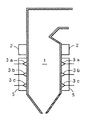
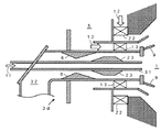
本実施例の主燃料として石炭を微粉砕した微粉炭を用い、バイオマス燃料を補助燃料として用いる石炭焚きボイラの断面図を図1に示す。
Embodiments of the present invention will be described with reference to the drawings.
FIG. 1 shows a cross-sectional view of a coal-fired boiler using pulverized coal obtained by finely pulverizing coal as the main fuel and using biomass fuel as an auxiliary fuel.
図1は石炭焚きボイラの火炉壁面に設けられた風箱5内のバーナ3が三段が対向配置されたものを示す。この石炭焚きボイラの場合、図示していない6台の石炭微粉砕機が設置され、各バーナ段ごとに石炭微粉砕機が1台ずつ、合計3台設けられており、石炭微粉砕機で粉砕された微粉炭は気流搬送により各段のバーナ3a、3b、3cに供給される。バイオマス燃料を副燃料として使用する場合、3台の石炭微粉砕機の内の1台に代えてバイオマス燃料の微粉砕機を設ける。
FIG. 1 shows a structure in which three stages of
前記バイオマス燃料の微粉砕機からの微粉砕されたバイオマス燃料は燃料を燃焼させるバーナまで気流搬送されるが、前記バーナをバイオマス燃料の専焼バーナとする場合と、石炭を燃焼する微粉炭バーナ3に微粉炭とバイオマス燃料の微粉を供給して燃焼用空気と共に火炉内に噴出して燃焼させる混焼バーナとする場合とがある。
The finely pulverized biomass fuel from the biomass fuel pulverizer is air-flowed to the burner for burning the fuel, and the burner is used as a burner exclusively for biomass fuel, and the pulverized
前記したようにバイオマス燃料の粉砕動力を低減するためにはバイオマス燃料の微粉砕の程度を下げて粗粒のままで火炉1内へ供給して燃焼させることが望ましいが、火炉内の燃焼ガスの上昇速度に対して粗粒の終末沈降速度が速い場合、上昇流に粗粒が乗れずに火炉の炉底へ落下する。そこで粗粒が上昇流に乗れずに火炉の炉底へ落下する危険性をできるだけ小さくするために、図1では三段設けたバーナ3a、3b、3cのうちの最上段のバーナ段のバーナ3aにバイオマス燃料を投入している。
As described above, in order to reduce the pulverization power of the biomass fuel, it is desirable to reduce the degree of pulverization of the biomass fuel and supply it into the
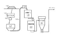
図2にバイオマス燃料専焼バーナ3aの構造図を示し、図7にバイオマス燃料と微粉炭との混焼バーナ3dの構造図を示す。また、図3にバイオマス燃料を粉砕して火炉に設けたバーナへ供給する設備を示す。 FIG. 2 shows a structural diagram of the biomass fuel-burning burner 3a, and FIG. 7 shows a structural diagram of a mixed-burning burner 3d of biomass fuel and pulverized coal. Moreover, the installation which grind | pulverizes biomass fuel and supplies it to the burner provided in the furnace in FIG. 3 is shown.
まず、図3について説明する。外部から搬入されてきたバイオマス燃料は一旦バイオマス貯蔵設備14に貯蔵される。通常は石炭焚きボイラが設けられた発電所構内の一次貯蔵場または設備に貯蔵される。バイオマス燃料は多数の産地から供給があること、産地の一次粉砕設備の状況がそれぞれ異なること、および季節や天候によるバイオマス燃料の性状が変動すること等がある。特に発電所へ供給されるバイオマス燃料の形状は不定形状であるため木材専用のタブグラインダ等の破砕機15が必要となる場合がある。前記破砕機15により径が15mmアンダー程度の中程度の粒度にバイオマス燃料が破砕され、磁選機16で磁性金属を除き受け入れホッパ17に供給される。
First, FIG. 3 will be described. The biomass fuel carried in from the outside is once stored in the
バイオマス燃料を前記受け入れホッパ17から流路18を経て貯蔵ビン19に入れて、次に火炉内での浮遊燃焼が可能な粒度まで粉砕するために微粉砕機20へ定量供給される。微粉砕機20での所定粒度は、バイオマス燃料の原料種類によって異なるが、例えば2〜3mmアンダまで微粉砕される。微粉砕機20からの微粉には粉塵も含まれるため、一旦バグフィルタ21にて捕集した後、火炉に設けられたバイオマス燃焼装置に供給され、燃焼される。
Biomass fuel is fed from the receiving
また、バグフィルタ21を使用する他の理由は、バイオマス燃料に含まれる水分を除かないまま、バイオマス燃料を直接燃焼装置に供給した場合には火炉内へ水分が持ち込まれるため、ボイラの燃焼効率が低下することになってしまう。そのため、バグフィルタ21により、気相中の水分を捕集する。また、特にバグフィルタ21を用いて、サイクロンなど簡易捕集器を用いない理由は、前記簡易捕集器では、粒子が細かい粉塵の効果的な捕集が難しいからである。
Another reason for using the
なお、図示していないが簡易捕集器のサイクロンをバグフィルタ21の前段に設置して二段の粉塵除去法を採用するとバグフィルタ21の負荷低減効果がある。
Although not shown, if the cyclone of the simple collector is installed in front of the
図2は本実施例のバイオマス燃料の専焼バーナ3aを示す。図2においてバイオマス燃料11は下方向からバーナ3a内に流入し、バーナ3aの中心部の流路である中心部ノズル4を水平方向に流れ、火炉1内に噴出する方向に移動する。中心部ノズル4の先端部分には流れ方向に対して階段状に拡大部を有する保炎器9を設けている。また、バイオマス燃料11の流路である中心部ノズル4の外周には断熱スリーブ7を設けることができる。
FIG. 2 shows a biomass fuel burning burner 3a of this embodiment. In FIG. 2, the
前記保炎器9は、バイオマス燃料の流れに対して急拡大部分を有しており、火炉1の内部、すなわちバイオマス燃料11の炉内への噴出流に対して保炎器9とバイオマス燃料11の噴流との接触部分でバイオマス燃料の微粒のよどみ域が安定して形成され、このよどみ域が着火源となり安定して継続的にバイオマス燃料の燃焼が可能となる。また保炎器9の形状を階段状に拡大することでよどみ域が定常状態で存在し得る領域を形成し、かつ火炉1の内部に向かって保炎器9の形状が急拡大部を有することにより、大きなバイオマス燃料の微粒のよどみを形成させることができる。
The flame holder 9 has a rapidly expanding portion with respect to the flow of the biomass fuel, and the flame holder 9 and the
また、燃焼用空気12をバイオマス燃料11の流路である中心部ノズル4の外周から旋回させながら供給できるように旋回器13を設けた。旋回器13は燃焼用空気12に旋回をかける軸流旋回装置とした。バイオマス燃料11の搬送用空気量は、バイオマス燃料11を搬送し得る最小流量が決まっており、バイオマス燃料の燃焼時の空気比は主に燃焼用空気量を調節することにより調整することができる。本実施例ではバイオマス燃料の燃焼におけるバーナの空気比を0.6に設定した。
Further, a
図2に示す例では、バイオマス燃料11を供給する中心部ノズル4の周囲を断熱材7で覆う構造としている。バイオマス燃料11を燃焼させるバーナ3aに供給する燃焼用空気は、微粉炭の燃焼用に使用している燃焼用空気の一部を分岐させて供給しており、火炉1内での燃焼に支障が無いように、木質系バイオマス燃料の50%〜60%の含有水分量を目標の20%まで減少させるために300℃以上としている。一方で、バイオマス燃料は180度以上で熱分解することが知られており、特にバイオマス燃料の供給を停止した場合でも燃焼用空気はバーナの火炉内に面した部分の火炉内からの1000℃程度の高温燃焼ガスの輻射による過熱損傷を防止するためにそれよりは低い300℃以上の温度で最低流量を流しているが、バーナ内部に微量でも堆積したバイオマス燃料が燃焼用空気側からの伝熱によって高温になると自然発火することが考えられるため、これを防止するためにバイオマス燃料の流路と燃焼用空気の流路間に断熱構造を設けることは重要となる。
In the example shown in FIG. 2, the periphery of the
また、バイオマス燃料の粒度を、例えば3mmアンダー程度に粒度調整した場合にバイオマス燃料の供給流路の配管内部で偏流が発生する。偏流した状態でバーナ3aの中心部の流路である中心部ノズル4を火炉1に向けて水平方向に移動し、バイオマス燃料が火炉1の内部へ噴出されるとバイオマス燃料燃焼バーナ3a先端部から形成される火炎も炉内で偏った状態となり、安定燃焼が継続できない場合がある。また、図中の火炎の一部からの発光を光ファイバ等により光学的に分析することにより火炎の形成を監視する火炎検知器8での火炎検知が火炎が視野から外れることにより困難となり、失火信号を出す場合が起こり得る。このため図2ではバイオマス燃料11の偏流を防止する対策として中心部ノズル4内の中央に分散装置10を設け、偏って流れてくるバイオマス燃料を中心部ノズル4の内周壁面方向に向けて流し、互いに混合させてバイオマス燃料の濃度を略均一化するようにしている。
Further, when the particle size of the biomass fuel is adjusted to, for example, about 3 mm, a drift occurs inside the piping of the biomass fuel supply channel. When the
また中心部ノズル4内の上流部には逆火防止用のベンチュリー6を設け、逆火防止のための燃料の流速を上昇させる機能と共に前記分散装置10へバイオマス燃料粒子を衝突させるためのガイドの役目も担っている。
A
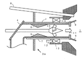
図7にバイオマス燃料と微粉炭との混焼バーナ3dの構造図を示す。
本バーナ3dは、バイオマス燃料の専焼バーナ3aと比較すると、微粉炭で火炎を形成させ、この火炎にバイオマス燃料11を投入する燃焼方式を採用することができるので、バイオマス燃料のみで火炎形成が必要なバイオマス燃料の専焼バーナ3aと比較して幅広い混焼率(微粉炭とバイオマス燃料の各投入熱量の比)に対応可能である。
FIG. 7 shows a structural diagram of a mixed burner 3d of biomass fuel and pulverized coal.
This burner 3d can adopt a combustion method in which a flame is formed with pulverized coal and the
図7に示すようにバイオマス燃料11はバーナ中心部流路である中心部ノズル31から火炉1内へ供給される。微粉炭はその外周にある流路32から炉内に向けて供給され、保炎器9で着火し安定火炎が形成される。
As shown in FIG. 7, the
なお、図7のバーナに風箱5に供給される燃焼用空気12は旋回器13、22により旋回流となり、火炉1に供給される。また、中心ノズル31の外周面の先端部には偏流体23が設けられている。この偏流体23は微粉炭の流路32の内周部側に濃縮された微粉炭流を形成させ、保炎器9の近傍で着火保炎を促進させる。
The combustion air 12 supplied to the
もし、この状態でバイオマス燃料11がバーナ中心流路の中心部ノズル31から供給されないと微粉炭火炎は形成されるもののバーナ中心部分には依然未着火領域がバーナ後流側の火炉内に残ることになる。つまり、バーナ中心部分は着火遅れが発生する。この状態が著しいと、未燃分の増加やバーナ後流側の火炉内の還元領域の縮小に起因してNOx生成量が増加することになるが、本実施例では中心部ノズル31にバイオマス燃料11を供給しており、バイオマス燃料が微粉炭より熱分解しやすいことから火炉1内に噴出されたバイオマス燃料11は急速に着火して、バーナ後流側の火炉内で火炎温度が高くなり、着火遅れが減少し、また還元領域の拡大化を図れ、微粉炭単独の燃焼と比較して未燃分とNOx発生量が減少する。
If the
また、微粉炭専焼バーナ3b、3cのみからなる石炭焚きボイラに対して、該石炭焚きボイラのバーナの一部を本実施例のバイオマス燃焼バーナ3aまたは混焼バーナ3dに取り替える運用も可能である。 Further, with respect to a coal fired boiler consisting of only pulverized coal burners 3b and 3c, it is possible to replace a part of the burner of the coal fired boiler with the biomass combustion burner 3a or the mixed fired burner 3d of this embodiment.
例えば本実施例のバイオマス燃焼バーナ3aまたは混焼バーナ3dを用いると、揮発分が多い燃料が使用でき、また生成する火炎領域は、還元領域が大きいという有利な特徴があり、これらの特徴点を活かすために当該バーナ3a、3dの空気比を、微粉炭専焼バーナ3b、3cの空気比と比較して低下させた運用を行うことで炉内の脱硝効果の改善が可能である。 For example, when the biomass combustion burner 3a or the mixed combustion burner 3d of the present embodiment is used, a fuel with a high volatile content can be used, and the generated flame region has an advantageous feature that the reduction region is large, and these feature points are utilized. Therefore, it is possible to improve the denitration effect in the furnace by performing an operation in which the air ratio of the burners 3a and 3d is lowered compared with the air ratio of the pulverized coal-burning burners 3b and 3c.
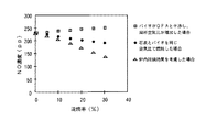
本実施例のバイオマス燃焼バーナ3aによる低NOx燃焼効果を、図4と図5を用いて説明する。
図4は、微粉炭燃焼の試験装置において、バイオマス燃料の専焼バーナ3a(図2)を微粉炭バーナ3b、3cとは別に設置して燃焼試験した結果である。
The low NOx combustion effect by the biomass combustion burner 3a of a present Example is demonstrated using FIG. 4 and FIG.
FIG. 4 shows the result of a combustion test in which a biomass fuel-burning burner 3a (FIG. 2) is installed separately from the pulverized coal burners 3b and 3c in a test apparatus for pulverized coal combustion.
バーナの配置は、下段から上段に順に微粉炭バーナ3b、バイオマス燃料専焼バーナ3a及びOFA2を配置した。炉内脱硝効果を期待した試験では、バイオマス燃料専焼バーナ3aからOFA2までのガス滞留時間(到達時間)を0.8秒に設定した。バイオマス燃料とOFA2が干渉した場合は、バイオマス燃料専焼バーナ3aからバイオマス燃料と二段燃焼用空気量に相当する空気量を供給した。
松材から成るバイオマス燃料を原料として用いた。図4において熱量ベースでの混焼率とNOx濃度との関係を示した。
なお、混焼率はバイオマス燃料の投入熱量を微粉炭とバイオマス燃料の合計投入熱量で割った値である。
As for the arrangement of the burners, the pulverized coal burner 3b, the biomass fuel-burning burner 3a, and the
Biomass fuel consisting of pine wood was used as a raw material. FIG. 4 shows the relationship between the heat ratio and the NOx concentration.
The mixed combustion rate is a value obtained by dividing the input heat amount of biomass fuel by the total input heat amount of pulverized coal and biomass fuel.
微粉炭とバイオマス燃料を同じ空気比で供給した場合をベースとし、バイオマス燃料の燃焼時の空気比を脱硝効果を考慮して0.6に下げるとNOxが混焼率に比例して低下するが、バイオマス燃料に二段燃焼用空気量を合わせて供給すると、混焼率が増加するにつれてNOxが増加する。これは、OFA2部分でのNOx再生が増加するためである。この結果は、二段燃焼が行われる石炭焚きボイラにおいてはバイオマス燃料専焼バーナ3aによるバイオマス燃料の供給位置には適正な位置が存在することを示している。 Based on the case where pulverized coal and biomass fuel are supplied at the same air ratio, NOx decreases in proportion to the co-firing rate when the air ratio at the time of combustion of biomass fuel is reduced to 0.6 in consideration of the denitration effect, When the amount of air for two-stage combustion is supplied together with biomass fuel, NOx increases as the mixed combustion rate increases. This is because NOx regeneration in the OFA2 portion increases. This result shows that in a coal fired boiler in which two-stage combustion is performed, there is an appropriate position for supplying biomass fuel by the biomass fuel-burning burner 3a.
そこで、次に保炎効果について実験的に明らかにする目的で、図5に示す保炎器9を付けないバイオマス専焼バーナ3aを設置し、下段から上段に順に微粉炭バーナ3b、保炎器無しのバイオマス燃焼バーナ3a、OFA2の構成で燃焼試験をして前記試験結果と比較した。混焼率は15%で一定とした。図4のデータに加えたその結果を図6に示す。保炎器無しの場合に、図4のバイオマス燃料専焼バーナ3aから二段燃焼用空気を供給した場合(空気比を増加した場合)のNOx濃度に近い値になった。 Therefore, for the purpose of experimentally clarifying the flame holding effect, the biomass-burning burner 3a without the flame holder 9 shown in FIG. 5 is installed, and the pulverized coal burner 3b and the flame holder are not provided in order from the lower stage to the upper stage. A combustion test was conducted with the configuration of the biomass combustion burner 3a and OFA2, and the results were compared with the test results. The mixed firing rate was fixed at 15%. The result added to the data of FIG. 4 is shown in FIG. In the case of no flame holder, the NOx concentration was close to that when the two-stage combustion air was supplied from the biomass fuel-burning burner 3a of FIG. 4 (when the air ratio was increased).
これらの結果から、OFA2と炉内燃焼ガスの流動面で干渉しない位置にバイオマス燃料を供給すること、加えてバイオマス燃料は急速に着火させる必要があることを実験的に明らかにした。
From these results, it was experimentally clarified that biomass fuel should be supplied to a position where it does not interfere with the flow surface of the
本発明は、バイオマス燃料を補助燃料として利用することで、燃焼排ガスの低NOx化と高効率燃焼を達成させ、CO2排出量を削減する石炭焚きボイラなどの燃焼技術として利用できる。 INDUSTRIAL APPLICABILITY The present invention can be used as a combustion technique such as a coal-fired boiler that achieves low NOx and high-efficiency combustion of combustion exhaust gas and reduces CO 2 emission by using biomass fuel as an auxiliary fuel.
1 火炉 2 空気噴出口(OFA)
3 バーナ
3a バイオマス燃料専焼バーナ
3b、3c 微粉炭バーナ
3d バイオマス燃料と微粉炭との混焼バーナ
4 中心部ノズル 5 風箱
6 ベンチュリー 7 断熱スリーブ
8 火炎検知器 9 保炎器
10 分散装置 11 バイオマス燃料
12 燃焼用空気 13 旋回器
14 バイオマス貯蔵設備 15 破砕機
16 磁選機 17 受け入れホッパ
18 流路 19 貯蔵ビン
20 微粉砕機 21 バグフィルタ
22 旋回器 23 偏流体
31 中心部ノズル 32 微粉炭流路
1
3 Burner 3a Biomass fuel exclusive burner 3b, 3c Pulverized coal burner 3d Coal fired burner of biomass fuel and pulverized
Claims (9)
粉砕された微粉炭及びバイオマス燃料の微粉とを別系統でそれぞれ供給する微粉炭燃料供給流路及びバイオマス燃料供給流路と、バイオマス燃料供給流路の先端に設けたバイオマス燃料の微粉を燃焼装置内に噴出するバイオマス燃料噴出ノズルと、該バイオマス燃料噴出ノズルの外周側に設けたバイオマス燃料用の燃焼用空気ノズルと、前記バイオマス燃料噴出ノズルの先端に設けた保炎器と
を備えたことを特徴とするバイオマス燃料の燃焼装置。 In a combustion apparatus for biomass fuel, in which coal is the main fuel, biomass fuel is used as a secondary fuel, and the combustion air is supplied into the furnace and burned.
The pulverized coal fuel supply channel and biomass fuel supply channel for supplying the pulverized pulverized coal and biomass fuel pulverized powder in separate systems, respectively, and the biomass fuel fine powder provided at the tip of the biomass fuel supply channel in the combustion device A biomass fuel jet nozzle that jets into the biomass fuel, a combustion air nozzle for biomass fuel provided on the outer peripheral side of the biomass fuel jet nozzle, and a flame holder provided at the tip of the biomass fuel jet nozzle Biomass fuel combustion device.
該微粉炭噴出部とは別に前記バイオマス燃料噴出ノズルを配し、
前記バイオマス燃料噴出ノズルの外周側にバイオマス燃料を燃焼させる燃焼用空気を供給する燃焼用空気ノズルを配し、
前記バイオマス燃料噴出ノズルの先端に設けた階段状拡大構造の保炎器
を備えたことを特徴とする請求項1記載のバイオマス燃料の燃焼装置。 Connected to the pulverized coal fuel supply flow path and arranged with a pulverized coal ejection section for ejecting pulverized coal,
In addition to the pulverized coal ejection part, the biomass fuel ejection nozzle is arranged,
Arranging a combustion air nozzle for supplying combustion air for burning biomass fuel on the outer peripheral side of the biomass fuel ejection nozzle,
The biomass fuel combustion apparatus according to claim 1, further comprising a flame holder having a step-like enlarged structure provided at a tip of the biomass fuel ejection nozzle.
前記バイオマス燃料噴出ノズルの外周側に微粉炭を噴出する微粉炭噴出ノズルを配し、 前記微粉炭噴出ノズルの外周側にバイオマス燃料と微粉炭燃料とを燃焼させる燃焼用空気を供給する燃焼用空気ノズルを配し、
前記微粉炭噴出ノズルの先端に設けた階段状拡大構造の保炎器
を備えたことを特徴とする請求項1記載のバイオマス燃料の燃焼装置。 A biomass fuel injection nozzle that ejects fine powder of biomass fuel is arranged on the center side,
Combustion air for supplying pulverized coal injection nozzles for injecting pulverized coal to the outer peripheral side of the biomass fuel injection nozzle and supplying combustion air for burning biomass fuel and pulverized coal fuel to the outer peripheral side of the pulverized coal injection nozzle Arrange the nozzle,
The biomass fuel combustion apparatus according to claim 1, further comprising a flame stabilizer having a step-like enlarged structure provided at a tip of the pulverized coal ejection nozzle.
粉砕された微粉炭を火炉内へ供給して、前記微粉炭とは別の系統からバイオマス燃料の微粉を火炉内で燃焼するときの局所空気比(バイオマス燃料の搬送用空気量にバイオマス燃料の燃焼用空気量を加えたものをバイオマス燃料の燃焼のための理論空気量で割った値)を0.6以下になるように、バイオマス燃料の微粉と共に火炉へ供給して燃焼させることを特徴としたバイオマス燃料の燃焼方法。 In the method of burning biomass fuel, coal is used as the main fuel, and biomass fuel is used as the auxiliary fuel in the furnace together with the combustion air.
When the pulverized pulverized coal is supplied into the furnace and the biomass fuel pulverized powder is burned in the furnace from a system different from the pulverized coal, the local air ratio (combustion of biomass fuel into the amount of biomass fuel transported) (The value obtained by dividing the amount of air added by the theoretical amount of air for combustion of biomass fuel) is 0.6 or less, and is supplied to the furnace together with the fine powder of biomass fuel for combustion. Biomass fuel combustion method.
Priority Applications (1)
| Application Number | Priority Date | Filing Date | Title |
|---|---|---|---|
| JP2004103275A JP4791701B2 (en) | 2004-03-31 | 2004-03-31 | Biomass fuel combustion apparatus and method |
Applications Claiming Priority (1)
| Application Number | Priority Date | Filing Date | Title |
|---|---|---|---|
| JP2004103275A JP4791701B2 (en) | 2004-03-31 | 2004-03-31 | Biomass fuel combustion apparatus and method |
Publications (2)
| Publication Number | Publication Date |
|---|---|
| JP2005291534A true JP2005291534A (en) | 2005-10-20 |
| JP4791701B2 JP4791701B2 (en) | 2011-10-12 |
Family
ID=35324662
Family Applications (1)
| Application Number | Title | Priority Date | Filing Date |
|---|---|---|---|
| JP2004103275A Expired - Fee Related JP4791701B2 (en) | 2004-03-31 | 2004-03-31 | Biomass fuel combustion apparatus and method |
Country Status (1)
| Country | Link |
|---|---|
| JP (1) | JP4791701B2 (en) |
Cited By (15)
| Publication number | Priority date | Publication date | Assignee | Title |
|---|---|---|---|---|
| JP2009168315A (en) * | 2008-01-15 | 2009-07-30 | Bab-Hitachi Industrial Co | Combustion device for simultaneous combustion of coal and biomass |
| CN102418923A (en) * | 2011-11-30 | 2012-04-18 | 华中科技大学 | Coal dust collector |
| JP2012112595A (en) * | 2010-11-25 | 2012-06-14 | Mitsubishi Heavy Ind Ltd | Biomass and coal co-combustion system, and method of biomass and coal co-combustion |
| JP2013108640A (en) * | 2011-11-17 | 2013-06-06 | Babcock Hitachi Kk | Solid fuel boiler system and solid fuel burner |
| CN103175200A (en) * | 2011-12-26 | 2013-06-26 | 川崎重工业株式会社 | Biomass-only combustion burner, biomass-mixed combustion boiler, and biomass fuel combustion method |
| JP2013170733A (en) * | 2012-02-20 | 2013-09-02 | Nippon Steel & Sumitomo Metal Corp | Method for co-combusting pulverized coal and biomass fuel, and pulverized coal-fired boiler furnace |
| JP2013174370A (en) * | 2012-02-23 | 2013-09-05 | Mitsubishi Heavy Ind Ltd | Burner exclusive for biomass burning |
| WO2013141312A1 (en) | 2012-03-21 | 2013-09-26 | 川崎重工業株式会社 | Pulverized coal/biomass mixed-combustion burner and fuel combustion method |
| WO2013141311A1 (en) | 2012-03-21 | 2013-09-26 | 川崎重工業株式会社 | Pulverized coal/biomass mixed-combustion burner and fuel combustion method |
| US8574329B2 (en) | 2008-12-11 | 2013-11-05 | General Electric Company | Method of operating a gasifier |
| US8617271B2 (en) | 2008-12-11 | 2013-12-31 | General Electric Company | Method of retrofitting a coal gasifier |
| CN104749315A (en) * | 2015-02-13 | 2015-07-01 | 华中科技大学 | Carbon-containing solid fuel mixed combustion test device and method |
| JP2021188861A (en) * | 2020-06-03 | 2021-12-13 | 株式会社Ihi | Burner |
| CN115930221A (en) * | 2022-12-12 | 2023-04-07 | 北京天地融创科技股份有限公司 | Ammonia coal mixed combustion pilot test device and method |
| CN119755622A (en) * | 2024-11-28 | 2025-04-04 | 马鞍山当涂发电有限公司 | Biomass coupling blending combustion power generation device |
Families Citing this family (1)
| Publication number | Priority date | Publication date | Assignee | Title |
|---|---|---|---|---|
| CN110966604B (en) * | 2018-09-30 | 2021-10-12 | 宁波方太厨具有限公司 | Fire cover for gas stove |
Citations (9)
| Publication number | Priority date | Publication date | Assignee | Title |
|---|---|---|---|---|
| JPS59142316A (en) * | 1982-11-24 | 1984-08-15 | ダンフオス・エ−・エス | Vaporizing burner for liquid fuel |
| JPH0181414U (en) * | 1987-11-24 | 1989-05-31 | ||
| JPH07229447A (en) * | 1994-02-21 | 1995-08-29 | Mitsubishi Heavy Ind Ltd | Pressure spraying burner |
| JPH1089622A (en) * | 1996-09-09 | 1998-04-10 | Ishikawajima Harima Heavy Ind Co Ltd | Pulverized coal burner device |
| JPH11173510A (en) * | 1997-12-05 | 1999-06-29 | Babcock Hitachi Kk | Pulverized coal burner |
| JP2002243108A (en) * | 2001-02-19 | 2002-08-28 | Babcock Hitachi Kk | Mixed-fuel fired device of coal and biofuel and operating method thereof |
| JP2003130308A (en) * | 2001-10-30 | 2003-05-08 | Hitachi Ltd | Solid fuel combustion method and solid fuel combustion equipment |
| JP2003222310A (en) * | 2002-01-31 | 2003-08-08 | Babcock Hitachi Kk | Combustion device and method of biomass fuel |
| JP2003240227A (en) * | 2002-02-14 | 2003-08-27 | Hitachi Ltd | Solid fuel burner and method of burning solid fuel burner |
-
2004
- 2004-03-31 JP JP2004103275A patent/JP4791701B2/en not_active Expired - Fee Related
Patent Citations (9)
| Publication number | Priority date | Publication date | Assignee | Title |
|---|---|---|---|---|
| JPS59142316A (en) * | 1982-11-24 | 1984-08-15 | ダンフオス・エ−・エス | Vaporizing burner for liquid fuel |
| JPH0181414U (en) * | 1987-11-24 | 1989-05-31 | ||
| JPH07229447A (en) * | 1994-02-21 | 1995-08-29 | Mitsubishi Heavy Ind Ltd | Pressure spraying burner |
| JPH1089622A (en) * | 1996-09-09 | 1998-04-10 | Ishikawajima Harima Heavy Ind Co Ltd | Pulverized coal burner device |
| JPH11173510A (en) * | 1997-12-05 | 1999-06-29 | Babcock Hitachi Kk | Pulverized coal burner |
| JP2002243108A (en) * | 2001-02-19 | 2002-08-28 | Babcock Hitachi Kk | Mixed-fuel fired device of coal and biofuel and operating method thereof |
| JP2003130308A (en) * | 2001-10-30 | 2003-05-08 | Hitachi Ltd | Solid fuel combustion method and solid fuel combustion equipment |
| JP2003222310A (en) * | 2002-01-31 | 2003-08-08 | Babcock Hitachi Kk | Combustion device and method of biomass fuel |
| JP2003240227A (en) * | 2002-02-14 | 2003-08-27 | Hitachi Ltd | Solid fuel burner and method of burning solid fuel burner |
Cited By (23)
| Publication number | Priority date | Publication date | Assignee | Title |
|---|---|---|---|---|
| JP2009168315A (en) * | 2008-01-15 | 2009-07-30 | Bab-Hitachi Industrial Co | Combustion device for simultaneous combustion of coal and biomass |
| US8574329B2 (en) | 2008-12-11 | 2013-11-05 | General Electric Company | Method of operating a gasifier |
| US9365784B2 (en) | 2008-12-11 | 2016-06-14 | General Electric Company | Method of reducing oxygen requirement of a coal gasifier |
| US8617271B2 (en) | 2008-12-11 | 2013-12-31 | General Electric Company | Method of retrofitting a coal gasifier |
| JP2012112595A (en) * | 2010-11-25 | 2012-06-14 | Mitsubishi Heavy Ind Ltd | Biomass and coal co-combustion system, and method of biomass and coal co-combustion |
| JP2013108640A (en) * | 2011-11-17 | 2013-06-06 | Babcock Hitachi Kk | Solid fuel boiler system and solid fuel burner |
| CN102418923A (en) * | 2011-11-30 | 2012-04-18 | 华中科技大学 | Coal dust collector |
| WO2013099593A1 (en) | 2011-12-26 | 2013-07-04 | 川崎重工業株式会社 | Biomass-only combustion burner, biomass-mixed combustion boiler, and biomass fuel combustion method |
| JP2013133944A (en) * | 2011-12-26 | 2013-07-08 | Kawasaki Heavy Ind Ltd | Biomass mono-fuel combustion burner, biomass multi-fuel combustion boiler, and biomass fuel combustion method |
| US10309647B2 (en) | 2011-12-26 | 2019-06-04 | Kawasaki Jukogyo Kabushiki Kaisha | Biomass combustion burner, biomass-mixed fired boiler, and biomass fuel combustion method |
| CN103175200A (en) * | 2011-12-26 | 2013-06-26 | 川崎重工业株式会社 | Biomass-only combustion burner, biomass-mixed combustion boiler, and biomass fuel combustion method |
| KR101609962B1 (en) * | 2011-12-26 | 2016-04-06 | 가와사키 쥬코교 가부시키가이샤 (디/비/에이 가와사키 헤비 인더스트리즈, 리미티드) | Biomass-only combustion burner, biomass-mixed combustion boiler, and biomass fuel combustion method |
| JP2013170733A (en) * | 2012-02-20 | 2013-09-02 | Nippon Steel & Sumitomo Metal Corp | Method for co-combusting pulverized coal and biomass fuel, and pulverized coal-fired boiler furnace |
| JP2013174370A (en) * | 2012-02-23 | 2013-09-05 | Mitsubishi Heavy Ind Ltd | Burner exclusive for biomass burning |
| WO2013141311A1 (en) | 2012-03-21 | 2013-09-26 | 川崎重工業株式会社 | Pulverized coal/biomass mixed-combustion burner and fuel combustion method |
| US10107492B2 (en) | 2012-03-21 | 2018-10-23 | Kawasaki Jukogyo Kabushiki Kaisha | Biomass-mixed, pulverized coal-fired burner and fuel combustion method |
| US10281148B2 (en) | 2012-03-21 | 2019-05-07 | Kawasaki Jukogyo Kabushiki Kaisha | Biomass-mixed, pulverized coal-fired burner and fuel combustion method |
| WO2013141312A1 (en) | 2012-03-21 | 2013-09-26 | 川崎重工業株式会社 | Pulverized coal/biomass mixed-combustion burner and fuel combustion method |
| CN104749315A (en) * | 2015-02-13 | 2015-07-01 | 华中科技大学 | Carbon-containing solid fuel mixed combustion test device and method |
| JP2021188861A (en) * | 2020-06-03 | 2021-12-13 | 株式会社Ihi | Burner |
| JP7415809B2 (en) | 2020-06-03 | 2024-01-17 | 株式会社Ihi | Burna |
| CN115930221A (en) * | 2022-12-12 | 2023-04-07 | 北京天地融创科技股份有限公司 | Ammonia coal mixed combustion pilot test device and method |
| CN119755622A (en) * | 2024-11-28 | 2025-04-04 | 马鞍山当涂发电有限公司 | Biomass coupling blending combustion power generation device |
Also Published As
| Publication number | Publication date |
|---|---|
| JP4791701B2 (en) | 2011-10-12 |
Similar Documents
| Publication | Publication Date | Title |
|---|---|---|
| JP4150968B2 (en) | Solid fuel burner and combustion method of solid fuel burner | |
| JP4969015B2 (en) | Solid fuel burner and combustion method using solid fuel burner | |
| JP4791701B2 (en) | Biomass fuel combustion apparatus and method | |
| KR100515013B1 (en) | Solid fuel burner, burning method using the same, combustion apparatus and method of operating the combustion apparatus | |
| JP5897363B2 (en) | Pulverized coal biomass mixed burner | |
| JP5897364B2 (en) | Pulverized coal biomass mixed burner | |
| JP2010242999A (en) | Method and device for directly pulverizing and burning woody biomass and boiler system | |
| EP2799770B1 (en) | Biomass fuel combustion method | |
| JPWO2002012791A1 (en) | Solid fuel burner and combustion method using solid fuel burner | |
| JP3890497B2 (en) | Solid fuel burner and combustion method of solid fuel burner | |
| JP4056752B2 (en) | Biomass fuel combustion apparatus and method | |
| JPH0447204B2 (en) | ||
| JP3891958B2 (en) | Combustion apparatus and method | |
| JPH1038217A (en) | Fine powdered coal combustion burner | |
| JPH04214102A (en) | Pulverized coal boiler, pulverized coal boiler system, and pulverized coal burner | |
| JP4386179B2 (en) | Boiler equipment | |
| JP2007101083A (en) | Coal / wood co-firing method, co-firing burner and co-firing equipment | |
| RU2282105C2 (en) | Solid fuel burner (variants), fuel combustion device (variants), boiler (variants), fuel combustion method (variants), boiler system and power plant (variants) | |
| JP3899457B2 (en) | Solid fuel burner and combustion method of solid fuel burner | |
| JP2002048306A (en) | Combustion burner and combustion device having the burner | |
| JP2954628B2 (en) | Pulverized coal burner | |
| JP2005241107A (en) | Biomass mixing and burning device and mixing and burning method | |
| JP2776575B2 (en) | Pulverized coal combustion equipment | |
| RU2253799C1 (en) | Vortex furnace | |
| Arkhipov et al. | Staged combustion of Kuznetsk coals in flames at thermal power stations |
Legal Events
| Date | Code | Title | Description |
|---|---|---|---|
| A621 | Written request for application examination |
Free format text: JAPANESE INTERMEDIATE CODE: A621 Effective date: 20070309 |
|
| A131 | Notification of reasons for refusal |
Free format text: JAPANESE INTERMEDIATE CODE: A131 Effective date: 20081008 |
|
| A521 | Written amendment |
Free format text: JAPANESE INTERMEDIATE CODE: A523 Effective date: 20081205 |
|
| A131 | Notification of reasons for refusal |
Free format text: JAPANESE INTERMEDIATE CODE: A131 Effective date: 20090520 |
|
| A521 | Written amendment |
Free format text: JAPANESE INTERMEDIATE CODE: A523 Effective date: 20090721 |
|
| A02 | Decision of refusal |
Free format text: JAPANESE INTERMEDIATE CODE: A02 Effective date: 20100113 |
|
| A521 | Written amendment |
Free format text: JAPANESE INTERMEDIATE CODE: A523 Effective date: 20100408 |
|
| A911 | Transfer of reconsideration by examiner before appeal (zenchi) |
Free format text: JAPANESE INTERMEDIATE CODE: A911 Effective date: 20100419 |
|
| A912 | Removal of reconsideration by examiner before appeal (zenchi) |
Free format text: JAPANESE INTERMEDIATE CODE: A912 Effective date: 20100625 |
|
| A521 | Written amendment |
Free format text: JAPANESE INTERMEDIATE CODE: A523 Effective date: 20110617 |
|
| A01 | Written decision to grant a patent or to grant a registration (utility model) |
Free format text: JAPANESE INTERMEDIATE CODE: A01 |
|
| A61 | First payment of annual fees (during grant procedure) |
Free format text: JAPANESE INTERMEDIATE CODE: A61 Effective date: 20110722 |
|
| FPAY | Renewal fee payment (event date is renewal date of database) |
Free format text: PAYMENT UNTIL: 20140729 Year of fee payment: 3 |
|
| R150 | Certificate of patent or registration of utility model |
Ref document number: 4791701 Country of ref document: JP Free format text: JAPANESE INTERMEDIATE CODE: R150 Free format text: JAPANESE INTERMEDIATE CODE: R150 |
|
| R250 | Receipt of annual fees |
Free format text: JAPANESE INTERMEDIATE CODE: R250 |
|
| S111 | Request for change of ownership or part of ownership |
Free format text: JAPANESE INTERMEDIATE CODE: R313115 |
|
| R350 | Written notification of registration of transfer |
Free format text: JAPANESE INTERMEDIATE CODE: R350 |
|
| R250 | Receipt of annual fees |
Free format text: JAPANESE INTERMEDIATE CODE: R250 |
|
| R250 | Receipt of annual fees |
Free format text: JAPANESE INTERMEDIATE CODE: R250 |
|
| R250 | Receipt of annual fees |
Free format text: JAPANESE INTERMEDIATE CODE: R250 |
|
| R250 | Receipt of annual fees |
Free format text: JAPANESE INTERMEDIATE CODE: R250 |
|
| LAPS | Cancellation because of no payment of annual fees |