JP2005291504A - Method and apparatus for reducing combustor emissions - Google Patents
Method and apparatus for reducing combustor emissions Download PDFInfo
- Publication number
- JP2005291504A JP2005291504A JP2003402389A JP2003402389A JP2005291504A JP 2005291504 A JP2005291504 A JP 2005291504A JP 2003402389 A JP2003402389 A JP 2003402389A JP 2003402389 A JP2003402389 A JP 2003402389A JP 2005291504 A JP2005291504 A JP 2005291504A
- Authority
- JP
- Japan
- Prior art keywords
- mixer
- pilot
- swirler
- combustor
- main
- Prior art date
- Legal status (The legal status is an assumption and is not a legal conclusion. Google has not performed a legal analysis and makes no representation as to the accuracy of the status listed.)
- Granted
Links
Images
Classifications
-
- F—MECHANICAL ENGINEERING; LIGHTING; HEATING; WEAPONS; BLASTING
- F23—COMBUSTION APPARATUS; COMBUSTION PROCESSES
- F23R—GENERATING COMBUSTION PRODUCTS OF HIGH PRESSURE OR HIGH VELOCITY, e.g. GAS-TURBINE COMBUSTION CHAMBERS
- F23R3/00—Continuous combustion chambers using liquid or gaseous fuel
- F23R3/28—Continuous combustion chambers using liquid or gaseous fuel characterised by the fuel supply
- F23R3/286—Continuous combustion chambers using liquid or gaseous fuel characterised by the fuel supply having fuel-air premixing devices
-
- F—MECHANICAL ENGINEERING; LIGHTING; HEATING; WEAPONS; BLASTING
- F23—COMBUSTION APPARATUS; COMBUSTION PROCESSES
- F23R—GENERATING COMBUSTION PRODUCTS OF HIGH PRESSURE OR HIGH VELOCITY, e.g. GAS-TURBINE COMBUSTION CHAMBERS
- F23R3/00—Continuous combustion chambers using liquid or gaseous fuel
- F23R3/02—Continuous combustion chambers using liquid or gaseous fuel characterised by the air-flow or gas-flow configuration
- F23R3/04—Air inlet arrangements
- F23R3/10—Air inlet arrangements for primary air
- F23R3/12—Air inlet arrangements for primary air inducing a vortex
- F23R3/14—Air inlet arrangements for primary air inducing a vortex by using swirl vanes
-
- F—MECHANICAL ENGINEERING; LIGHTING; HEATING; WEAPONS; BLASTING
- F23—COMBUSTION APPARATUS; COMBUSTION PROCESSES
- F23R—GENERATING COMBUSTION PRODUCTS OF HIGH PRESSURE OR HIGH VELOCITY, e.g. GAS-TURBINE COMBUSTION CHAMBERS
- F23R3/00—Continuous combustion chambers using liquid or gaseous fuel
- F23R3/28—Continuous combustion chambers using liquid or gaseous fuel characterised by the fuel supply
- F23R3/34—Feeding into different combustion zones
- F23R3/343—Pilot flames, i.e. fuel nozzles or injectors using only a very small proportion of the total fuel to insure continuous combustion
Landscapes
- Engineering & Computer Science (AREA)
- Chemical & Material Sciences (AREA)
- Combustion & Propulsion (AREA)
- Mechanical Engineering (AREA)
- General Engineering & Computer Science (AREA)
Abstract
Description
本出願は、一般的に燃焼器に関し、より具体的には、ガスタービンの燃焼器に関する。 The present application relates generally to combustors, and more specifically to gas turbine combustors.
大気汚染に関する世界規模の関心によって、国内でも国際的にも、より厳しいエミッション基準が導入されるようになった。工業用ガスタービンからの汚染物質の排出(エミッション)は、米国環境保護庁(EPA)の基準の対象となり、この基準は、窒素酸化物(NOx)、未燃炭化水素(HC)、一酸化炭素(CO)の排出を規制している。一般に、エンジンのエミッションは、2種類、すなわち高火炎温度によって形成されたもの(NOx)と、燃料・空気の反応が完全には進行することができない低火炎温度によって形成されたもの(HC及びCO)とに分類される。 Global concerns about air pollution have led to more stringent emission standards both domestically and internationally. Emissions of pollutants from industrial gas turbines are subject to US Environmental Protection Agency (EPA) standards, which include nitrogen oxides (NOx), unburned hydrocarbons (HC), and carbon monoxide. It regulates (CO) emissions. In general, there are two types of engine emissions: those produced by high flame temperatures (NOx) and those produced by low flame temperatures where the reaction between fuel and air cannot proceed completely (HC and CO). ).
少なくとも一部の公知のガスタービン燃焼器は、10個から30個の範囲のミキサを備え、これらミキサが、高速空気をディーゼル燃料などの液体燃料及び/又は天然ガスなどの気体燃料と混合する。これらのミキサは通常、流入空気を旋回させて火炎の安定性及び混合を高めるスワーラの中央に配置された単一の燃料噴射器を含む。燃料噴射器及びミキサの両方が、燃焼器ドーム上に配置される。 At least some known gas turbine combustors include a range of 10 to 30 mixers that mix high speed air with liquid fuels such as diesel fuel and / or gaseous fuels such as natural gas. These mixers typically include a single fuel injector located in the center of the swirler that swirls the incoming air to enhance flame stability and mixing. Both the fuel injector and the mixer are located on the combustor dome.
大半の空気誘導式ガスタービンエンジンの場合、ミキサ内での燃料対空気比はリッチ(濃厚)である。ガスタービン燃焼器の燃焼器全体での燃空比はリーン(希薄)であるので、燃焼器を出る前に、付加的な空気が個別の希釈孔から加えられる。噴射された燃料が燃焼する前に気化され混合されなければならない部位であるドームと、リッチなドーム混合気に対して空気が加えられる部位である希釈孔の近傍との両方において、不完全な混合及びホットスポットが発生する可能性がある。他の空気誘導式エンジンでは、燃料リーン(希薄)混合気を形成する乾式低エミッション型(DLE)燃焼器が使用されている。燃焼器全体にわたる混合気が燃料リーンであるので、DLE燃焼器は一般的に希釈孔を持たない。 For most air induction gas turbine engines, the fuel to air ratio in the mixer is rich. Because the fuel-air ratio across the combustor of a gas turbine combustor is lean, additional air is added through individual dilution holes before exiting the combustor. Incomplete mixing in both the dome, where the injected fuel must be vaporized and mixed before combustion, and in the vicinity of the dilution hole, where air is added to the rich dome mixture And hot spots may occur. Other air induction engines use dry low emission (DLE) combustors that form a fuel lean mixture. DLE combustors generally do not have dilution holes because the air-fuel mixture throughout the combustor is fuel lean.
1つの最新式のリーンドーム式燃焼器は、該燃焼器が各燃料ノズル上に2つの半径方向に重なったミキサを備え、これが該燃焼器の前方から見ると2つの環状の(アニュラ状の)リングのように見えるので、二重アニュラ型燃焼器(DAC)と呼ばれる。更にミキサの列を加えることで、異なる条件において作動するように調整することが可能になる。アイドリング時、外側ミキサに燃料が供給され、該外側ミキサは、アイドリング状態において効率よく作動するように設計されている。高出力作動時、燃料及び空気の大部分が内側アニュラスに供給された状態で、両方のミキサに燃料が供給され、該内側アニュラスは、高出力作動時に最も効率よくかつエミッションがほとんどない状態で作動するように設計されている。ミキサは、各ドームにおいて最適な作動をするように調整されているが、ドーム間の境界面では広い領域にわたってCO反応が消炎し、そのことが、これらの設計のCOエミッションを同様のリッチドーム式の単一アニュラ型燃焼器(SAC)よりも高くする。このような燃焼器は、低出力時のエミッションと高出力時のNOxとの間で妥協したものとなっている。 One state-of-the-art lean dome combustor comprises two radially overlapping mixers on each fuel nozzle, which are two annular (annular) when viewed from the front of the combustor. Because it looks like a ring, it is called a double annular combustor (DAC). In addition, by adding an array of mixers, it is possible to adjust to operate at different conditions. When idling, fuel is supplied to the outer mixer, which is designed to operate efficiently in idling conditions. During high power operation, fuel is supplied to both mixers with most of the fuel and air supplied to the inner annulus, which operates most efficiently and with little emissions during high power operation. Designed to be. The mixers are tuned for optimal operation at each dome, but the CO reaction is extinguished over a wide area at the interface between the domes, which makes the CO emissions of these designs similar to the rich dome style. Higher than the single annular combustor (SAC). Such a combustor is a compromise between low power emissions and high power NOx.
他の公知の燃焼器は、リーンドーム式燃焼器として作動する。パイロットステージとメインステージとを別個のドーム内に分離し、境界面に大きなCO消炎ゾーンを形成するのに代えて、ミキサには、同心であるが明確に区分されたパイロット及びメイン空気流路が装置内に組み込まれている。しかしながら、このような設計では、多くの場合燃料/空気混合の増進により高CO/HCエミッションを生じるので、低出力時のCO/HCエミッションとスモークエミッションとを同時に制御するのは困難である。メイン空気を旋回させることは当然、パイロット火炎を取り込み、火炎を消炎させる傾向にある。 Other known combustors operate as lean dome combustors. Instead of separating the pilot stage and the main stage in separate domes and forming a large CO extinguishing zone at the interface, the mixer has concentric but clearly separated pilot and main air flow paths. Built in the device. However, such a design often results in high CO / HC emissions due to increased fuel / air mixing, making it difficult to control CO / HC emissions and smoke emissions at low power simultaneously. Naturally swirling the main air tends to capture the pilot flame and extinguish the flame.
1つの態様において、燃焼器からのエミッションの量を低減するのを促進するようにガスタービンエンジンを作動させる方法が、提供される。燃焼器は、パイロットミキサと、メインミキサと、その間で延びる環状のセンタボデーとを備えるミキサ組立体を含む。この方法は、パイロットミキサ内の少なくとも1つのスワーラ翼とメインミキサ内に配置された少なくとも1つのスワーラ翼とを通して燃焼器内に燃料を噴射する段階を含む。 In one aspect, a method for operating a gas turbine engine to facilitate reducing the amount of emissions from a combustor is provided. The combustor includes a mixer assembly that includes a pilot mixer, a main mixer, and an annular centerbody extending therebetween. The method includes injecting fuel into the combustor through at least one swirler blade in the pilot mixer and at least one swirler blade disposed in the main mixer.
本発明の別の態様において、ガスタービン用の燃焼器が提供される。該燃焼器は、燃焼室と、環状のセンタボデーによって分離されたパイロット及びメイン回路を備えた燃料・空気プレミキサとを含む。パイロットミキサは、パイロット中心体と、該パイロット中心体の半径方向外側に位置しかつ該パイロット中心体に対して同心に取り付けられた少なくとも1つのアキシャル空気スワーラとを含む。メインミキサは、パイロットミキサの半径方向外側に位置しかつ該パイロットミキサに対して同心に整列される。メインミキサは、該メインミキサ内に燃料を噴射するように構成されたスワーラ翼を含む。メイン及びパイロットミキサの両方は、燃焼室の上流に配置される。環状のセンタボデーは、パイロットミキサとメインミキサとの間で延びる。センタボデーは、半径方向内側面と半径方向外側面とを含む。半径方向内側面は、収束部分と発散部分とを含む。 In another aspect of the invention, a combustor for a gas turbine is provided. The combustor includes a combustion chamber and a fuel / air premixer with a pilot and main circuit separated by an annular centerbody. The pilot mixer includes a pilot center body and at least one axial air swirler located radially outward of the pilot center body and mounted concentrically with the pilot center body. The main mixer is located radially outward of the pilot mixer and is concentrically aligned with the pilot mixer. The main mixer includes swirler blades configured to inject fuel into the main mixer. Both main and pilot mixers are located upstream of the combustion chamber. An annular centerbody extends between the pilot mixer and the main mixer. The centerbody includes a radially inner surface and a radially outer surface. The radially inner surface includes a converging portion and a diverging portion.
更に別の態様において、ガスタービンエンジンは、燃焼室と少なくとも1つの燃料・空気ミキサ組立体とを備える燃焼器を含む。ミキサ組立体は、燃焼器からのエミッションを制御するようになっており、環状のセンタボデーによって分離されたパイロット及びメイン回路を含む。パイロットミキサは、パイロット中心体と、該パイロット中心体の半径方向外側に位置した少なくとも1つのスワーラとを含む。メインミキサは、パイロットミキサの半径方向外側に位置しかつ該パイロットミキサに対して同心に整列される。メインミキサは、それを通して該メインミキサ内に燃料を噴射するよう構成された少なくとも1つのスワーラ翼を含む。メイン及びパイロットミキサは、両方とも燃焼室の上流に配置される。 In yet another aspect, a gas turbine engine includes a combustor comprising a combustion chamber and at least one fuel / air mixer assembly. The mixer assembly is adapted to control emissions from the combustor and includes a pilot and main circuit separated by an annular centerbody. The pilot mixer includes a pilot center body and at least one swirler located radially outward of the pilot center body. The main mixer is located radially outward of the pilot mixer and is concentrically aligned with the pilot mixer. The main mixer includes at least one swirler vane configured to inject fuel therethrough into the main mixer. Both the main and pilot mixer are located upstream of the combustion chamber.
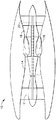
図1は、低圧圧縮機12と、高圧圧縮機14と、燃焼器16と備えるガスタービンエンジン10の概略図である。エンジン10は更に、高圧タービン18と、低圧タービン20とを備える。
FIG. 1 is a schematic diagram of a
作動中、空気は低圧圧縮機12を通って流れ、加圧された空気が、低圧圧縮機12から高圧圧縮機14に供給される。高度に加圧された空気は、燃焼器16に送られる。燃焼器16からの空気流(図1には図示せず)は、タービン18及び20を駆動する。1つの実施形態において、ガスタービンエンジン10は、CFM Internationalから入手可能なCFM型エンジンである。別の実施形態において、ガスタービン10は、オハイオ州シンシナチ所在のGeneral Electric Companyから入手可能なGE90型エンジンである。
In operation, air flows through the
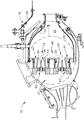
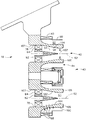
図2は、図1に示したエンジン10と同様なガスタービンエンジンに使用される燃焼器16の断面図であり、図3は、範囲3に沿った燃焼器16の部分拡大図である。燃焼器16は、環状の半径方向外側及び半径方向内側ライナ32、34で形成された燃焼ゾーン又は燃焼室30を含む。より具体的には、外側ライナ32は、燃焼室30の外側境界面を形成し、また内側ライナ34は、燃焼室30の内側境界面を形成する。ライナ32及び34は、該ライナ32及び34の周りで円周方向に延びた環状の燃焼器ケーシング36の半径方向内側に位置する。
FIG. 2 is a cross-sectional view of a
燃焼器16はまた、それぞれ外側及び内側ライナ32及び34の上流に取り付けられた環状のドーム40を含む。ドーム40は、燃焼室30の上流端を形成し、ミキサ組立体41が、ドーム40の周りで円周方向に間隔をおいて配置されて、燃料と空気の混合気を燃焼室30に供給する。燃焼器16は2つのアニュラ状ドーム40を含むので、該燃焼器16は二重アニュラ型燃焼器(DAC)として知られている。それに代えて、燃焼器16は、単一アニュラ型燃焼器(SAC)又は三重アニュラ型燃焼器とすることができる。
Combustor 16 also includes an
各ミキサ組立体41は、パイロットミキサ42と、メインミキサ44と、その間で延びる環状のセンタボデー43とを含む。センタボデー43は、パイロットミキサ42と流れ連通しかつ該パイロットミキサ42の下流に位置するチャンバ50を形成する。チャンバ50は対称軸線52を有し、ほぼ円筒形状である。パイロット中心体54が、チャンバ50内に延び、対称軸線52に対して対称的に取り付けられる。
Each
パイロットミキサ42はまた、一対の同心に取り付けられたスワーラ60を含む。より具体的には、例示的な実施形態において、スワーラ60は、アキシャルスワーラであり、パイロット内側スワーラ62とパイロット外側スワーラ64とを含む。パイロット内側スワーラ62は、環状であり、パイロット中心体54の周りで円周方向に配置される。各スワーラ62及び64は、複数の翼(図示せず)を含む。スワーラ64は、気体燃料の噴射のための、壁104及び106に沿った複数のオリフィス(図示せず)を含む。より具体的には、オロフィスは、スワーラ64の後縁に沿って配置され、チャンバ50内に下流方向に燃料を噴射する。更に、壁104に沿って配置されたオリフィスは、ベンチュリスロート107の上流及び下流の両方において半径方向内向きに燃料を噴射する。スワーラ62及び64は、低出力エンジン作動時に、所望の点火特性、リーン安定性、並びに一酸化炭素(CO)及び炭化水素(HC)の低エミッションをもたらすように設計されている。1つの実施形態において、パイロットスプリッタ(図示せず)が、半径方向にパイロット内側スワーラ62とパイロット外側スワーラ64との間に配置され、パイロット内側スワーラ62及びパイロット外側スワーラ64から下流方向に延びる。
パイロット外側スワーラ64は、パイロット内側スワーラ62の半径方向外側に位置し、かつセンタボデー43の半径方向内側通路面78の半径方向内側に位置する。より具体的には、パイロット外側スワーラ64は、パイロット内側スワーラ62の周りで円周方向に延び、半径方向にパイロット内側スワーラ62とセンタボデー43との間に位置する。1つの実施形態において、パイロットスワーラ62は、該パイロットスワーラを通って流れる空気を、パイロットスワーラ64を通って流れる空気と同じ方向に旋回させる。別の実施形態において、パイロット内側スワーラ62は、該パイロット内側スワーラを通って流れる空気を、パイロット外側スワーラ64が該パイロット外側スワーラを通って流れる空気を旋回させる第2の方向とは反対である第1の方向に旋回させる。
The pilot
メインミキサ44は、環状の空洞92を形成する環状のメインハウジング90を含む。メインミキサ44は、パイロットミキサ42に対して同心に整列され、パイロットミキサ42の周りで円周方向に延びる。環状のセンタボデー43は、パイロットミキサ42とメインミキサ44との間で延びて、メインミキサ空洞92の一部を形成する。
The
環状のセンタボデー43は、該センタボデー43の半径方向外側面100に取り付けられ、該センタボデー43からメインミキサ空洞92内に燃料を半径方向外向きに噴射する複数の噴射口98を含む。燃料噴射口98は、メインミキサ44内での円周方向の燃料と気体の混合を促進する。
The
1つの実施形態において、センタボデー43は、一対の円周方向に間隔をおいて配置された噴射口98の列を含む。別の実施形態において、センタボデー43は、複数の噴射口98を含むが、それら噴射口98は、円周方向に間隔をおいて配置された列には配列されていない。噴射口98の位置は、燃料と空気の混合の程度を調整して、窒素酸化物(NOx)の低エミッションを達成しかつ様々なエンジン作動状態の下で完全燃焼を保証するように選択される。更に、噴射口の位置はまた、燃焼の不安定さを減少させるか又は防止するのを可能にするように選択される。
In one embodiment, the
センタボデー43は、パイロットミキサ42とメインミキサ44とを分離する。従って、パイロットミキサ42は、パイロット作動中にメインミキサ44から隠蔽されて、パイロット性能の安定性及び効率性の改善を促進し、同時にCO及びHCエミッションを低減することを可能にする。更に、センタボデー43は、燃焼器16内に噴射されたパイロット燃料を完全燃焼させるのを促進するような形状にされている。より具体的には、センタボデー43の内側通路壁102は、入口部分103と、収束−発散面104と、後部シールド106とを含む。
The
収束−発散面104は、入口部分103から後部シールド106まで延び、パイロットミキサ42内にベンチュリスロート107を形成する。後部シールド106は、面104と外側面100との間で延びる。
The convergence-
メインミキサ44はまた、センタボデーの燃料噴射口98の上流に配置されたスワーラ140を含む。第1のスワーラ140は、ラジアル流サイクロンスワーラであり、該スワーラからの流体流が、対称軸線52に向かって半径方向内向きに吐出される。別の実施形態において、スワーラ140はコニカルスワーラである。より具体的には、スワーラ140は、燃料源(図示せず)に流れ連通した状態で連結され、従って該スワーラを通して燃料が噴射されるように構成され、それによって、スワーラ140から半径方向内向きに噴射され、また噴射口98から半径方向外向きに噴射された燃料の燃料・空気混合を向上させることが可能になる。別の実施形態において、第1のスワーラ140は、同一回転方向又は逆回転方向とすることができる対をなす旋回翼(図示せず)に分割される。
The
燃料供給システムは、燃焼器16に燃料を供給し、パイロット燃料回路とメイン燃料回路とを含む。パイロット燃料回路はパイロットミキサ42に燃料を供給し、またメイン燃料回路は、メインミキサ44に燃料を供給し、燃焼器16内で発生する窒素酸化物エミッションを制御するのに使用される複数の独立した燃料ステージを含む。
The fuel supply system supplies fuel to the
作動中、ガスタービンエンジン10が、始動され、アイドリング作動状態で作動されるとき、燃料と空気が燃焼器16に供給される。ガスタービンのアイドリング作動状態時、燃焼器16は、作動のためにパイロットミキサ42のみを使用する。パイロット燃料回路は、パイロット外側スワーラ64及び/又は壁104及び106を通して燃料を燃焼器16に噴射する。同時に、空気流が、パイロットスワーラ60及びメインミキサスワーラ140に流入する。パイロット空気流は、ミキサ中心対称軸線52とほぼ平行に流れる。より具体的には、空気流は、パイロットミキサ42の下流にあるパイロット火炎ゾーン内に導かれる。パイロット火炎は、ベンチュリスロート107に隣接しかつ該ベンチュリスロート107の下流側に留まった状態になり、メインミキサ44を通して吐出されるメイン空気流から環状のセンタボデー43によって隠蔽される。
In operation, fuel and air are supplied to the
エンジン10の出力がアイドリングから部分出力作動状態に増大すると、パイロットミキサ42への燃料流量が増加する。この作動モードにおいて、パイロット火炎による生成物は、メインミキサスワーラ140を通して吐出された空気流と混合され、燃焼室30から出る前に更に酸化される。
When the output of the
パイロットのみの部分出力モードから、燃料流がパイロットミキサ42及びメインミキサ44に供給される高出力作動モードへの移行が起こるのは、燃料流量がミキサ42および44の両方の完全燃焼を支えるのに十分になった時である。より具体的には、ガスタービンエンジン10がアイドリング作動状態から高出力作動状態に加速されると、付加的な燃料及び空気が、燃焼器16へ導かれる。パイロット燃料ステージに加えて、高出力作動状態時には、メインミキサ44は、スワーラ140を通して燃料が供給され、また燃料噴射口98から半径方向外向きに燃料が噴射される。メインミキサスワーラ140は、半径方向及び円周方向の燃料と空気の混合を促進して、燃焼のためのほぼ均一な燃料と空気の分布を形成する。燃料と空気の混合気を均一な分布とすることにより、完全燃焼が得られ、高出力作動時のNOxエミッションを減少させることが促進される。
The transition from the pilot only partial power mode to the high power operating mode where fuel flow is supplied to the
更に、パイロットミキサ42は、メインミキサ44内に吐出される燃料に対する点火源として作用するので、パイロットミキサ42及び環状のセンタボデー43は、メインミキサ44が低い火炎温度で作動するのを可能にする。最大出力時において、パイロットミキサ42とメインミキサ44との間で分割される燃料流量は、エミッション、作動性、燃焼音によって決定される。
Furthermore, since the
上述した燃焼器は、費用効果がありかつ高い信頼性がある。燃焼器は、パイロットミキサと、メインミキサと、センタボデーとを備えるミキサ組立体を含む。パイロットミキサは低出力作動時に使用され、メインミキサは中及び高出力作動時に使用される。アイドリング出力作動状態時には、燃焼器は、低エミッションで作動し、メインミキサにのみ空気が供給される。高出力作動状態時には、燃焼器はまた、スワーラを通して燃料をメインミキサに供給されて、メインミキサの燃料と空気の混合を改善する。より低い作動温度と燃焼の改善とにより、高出力作動時における作動効率の向上と燃焼器のエミッションの低減を可能にする。その結果、燃焼器は、高い燃焼効率と、低い一酸化炭素、窒素酸化物及びスモークエミッションとで作動する。 The combustor described above is cost effective and highly reliable. The combustor includes a mixer assembly that includes a pilot mixer, a main mixer, and a centerbody. The pilot mixer is used during low power operation and the main mixer is used during medium and high power operation. In the idling output operation state, the combustor operates with low emission, and air is supplied only to the main mixer. During high power operating conditions, the combustor is also supplied with fuel through a swirler to the main mixer to improve the fuel and air mixing of the main mixer. Lower operating temperatures and improved combustion allow for increased operating efficiency and reduced combustor emissions during high power operation. As a result, the combustor operates with high combustion efficiency and low carbon monoxide, nitrogen oxides and smoke emissions.
燃焼器組立体の例示的な実施形態を、上記に詳細に説明している。本発明のシステムは、本明細書に記載した特定の実施形態に限定されるものでなく、むしろ、各組立体の構成部品は、本明細書に記載した他の構成部品から独立して別個に使用することができる。各燃焼器組立体の構成部品はまた、他の燃焼器組立体の構成部品と組み合わせて使用することができる。 Exemplary embodiments of combustor assemblies are described in detail above. The system of the present invention is not limited to the specific embodiments described herein; rather, the components of each assembly are separate and independent of the other components described herein. Can be used. Each combustor assembly component can also be used in combination with other combustor assembly components.
特許請求の範囲で付された参照符号は、本発明の技術的範囲を狭めるためのものではなく、それらを容易に理解するためのものである。 Reference numerals in the claims are not intended to narrow the technical scope of the present invention but to facilitate understanding thereof.
10 ガスタービンエンジン
16 燃焼器
30 燃焼室
32 外側ライナ
34 内側ライナ
40 ドーム
41 ミキサ組立体
42 パイロットミキサ
43 センタボデー
44 メインミキサ
50 チャンバ
52 対称軸線
54 パイロット中心体
60 スワーラ
DESCRIPTION OF
Claims (10)
燃焼室(50)と、
前記燃焼室の上流に配置され、パイロット中心体(54)と前記パイロット中心体の半径方向外側に位置しかつ該パイロット中心体に対して同心に取り付けられた少なくとも1つのアキシャル空気スワーラ(60)とを含む、パイロットミキサ(42)と、
前記燃焼室の上流に配置され、前記パイロットミキサの半径方向外側に位置しかつ該パイロットミキサに対して同心に整列され、燃料を噴射するように構成された少なくとも1つのスワーラ(140)を含み、前記少なくとも1つのスワーラを通してその内部に燃料を噴射される、メインミキサと、
前記パイロットミキサと前記メインミキサとの間で延び、半径方向内側面(102)と半径方向外側面(104)とを含み、前記半径方向内側面が発散部分及び収束部分の少なくとも1つを含む、環状のセンタボデー(106)と、
を含むことを特徴とする燃焼器(16)。 A combustor (16) for a gas turbine (10),
A combustion chamber (50);
At least one axial air swirler (60) disposed upstream of the combustion chamber and positioned radially outward of the pilot center body and concentrically with the pilot center body; A pilot mixer (42) comprising:
Including at least one swirler (140) disposed upstream of the combustion chamber, positioned radially outward of the pilot mixer and concentrically aligned with the pilot mixer and configured to inject fuel; A main mixer, into which fuel is injected through the at least one swirler;
Extending between the pilot mixer and the main mixer, including a radially inner surface (102) and a radially outer surface (104), the radially inner surface including at least one of a diverging portion and a converging portion; An annular centerbody (106);
A combustor (16) comprising:
Applications Claiming Priority (1)
| Application Number | Priority Date | Filing Date | Title |
|---|---|---|---|
| US10/308,502 US6862889B2 (en) | 2002-12-03 | 2002-12-03 | Method and apparatus to decrease combustor emissions |
Publications (3)
| Publication Number | Publication Date |
|---|---|
| JP2005291504A true JP2005291504A (en) | 2005-10-20 |
| JP2005291504A5 JP2005291504A5 (en) | 2008-02-07 |
| JP4086767B2 JP4086767B2 (en) | 2008-05-14 |
Family
ID=32312225
Family Applications (1)
| Application Number | Title | Priority Date | Filing Date |
|---|---|---|---|
| JP2003402389A Expired - Fee Related JP4086767B2 (en) | 2002-12-03 | 2003-12-02 | Method and apparatus for reducing combustor emissions |
Country Status (3)
| Country | Link |
|---|---|
| US (2) | US6862889B2 (en) |
| EP (1) | EP1426690B1 (en) |
| JP (1) | JP4086767B2 (en) |
Cited By (2)
| Publication number | Priority date | Publication date | Assignee | Title |
|---|---|---|---|---|
| JP2016526638A (en) * | 2013-06-27 | 2016-09-05 | ブイ. モンロス,サージ | Multi-fuel system for internal combustion engines |
| JP2024080498A (en) * | 2022-12-02 | 2024-06-13 | トヨタ自動車株式会社 | Combustor and combustion nozzle suitable for hydrogen gas turbine |
Families Citing this family (20)
| Publication number | Priority date | Publication date | Assignee | Title |
|---|---|---|---|---|
| US7065972B2 (en) * | 2004-05-21 | 2006-06-27 | Honeywell International, Inc. | Fuel-air mixing apparatus for reducing gas turbine combustor exhaust emissions |
| US8348180B2 (en) * | 2004-06-09 | 2013-01-08 | Delavan Inc | Conical swirler for fuel injectors and combustor domes and methods of manufacturing the same |
| US7340900B2 (en) * | 2004-12-15 | 2008-03-11 | General Electric Company | Method and apparatus for decreasing combustor acoustics |
| US8479523B2 (en) * | 2006-05-26 | 2013-07-09 | General Electric Company | Method for gas turbine operation during under-frequency operation through use of air extraction |
| US20080083224A1 (en) * | 2006-10-05 | 2008-04-10 | Balachandar Varatharajan | Method and apparatus for reducing gas turbine engine emissions |
| US8099960B2 (en) * | 2006-11-17 | 2012-01-24 | General Electric Company | Triple counter rotating swirler and method of use |
| US7905093B2 (en) * | 2007-03-22 | 2011-03-15 | General Electric Company | Apparatus to facilitate decreasing combustor acoustics |
| US8567197B2 (en) * | 2008-12-31 | 2013-10-29 | General Electric Company | Acoustic damper |
| US8281597B2 (en) * | 2008-12-31 | 2012-10-09 | General Electric Company | Cooled flameholder swirl cup |
| US9671797B2 (en) | 2009-05-08 | 2017-06-06 | Gas Turbine Efficiency Sweden Ab | Optimization of gas turbine combustion systems low load performance on simple cycle and heat recovery steam generator applications |
| US9267443B2 (en) | 2009-05-08 | 2016-02-23 | Gas Turbine Efficiency Sweden Ab | Automated tuning of gas turbine combustion systems |
| US8437941B2 (en) | 2009-05-08 | 2013-05-07 | Gas Turbine Efficiency Sweden Ab | Automated tuning of gas turbine combustion systems |
| US9354618B2 (en) | 2009-05-08 | 2016-05-31 | Gas Turbine Efficiency Sweden Ab | Automated tuning of multiple fuel gas turbine combustion systems |
| US20110162375A1 (en) * | 2010-01-05 | 2011-07-07 | General Electric Company | Secondary Combustion Fuel Supply Systems |
| CN102506446B (en) * | 2011-10-13 | 2013-10-09 | 中国科学院工程热物理研究所 | A fuel and air mixing device for a low-pollution combustor of a gas turbine |
| WO2014137412A1 (en) | 2013-03-05 | 2014-09-12 | Rolls-Royce Corporation | Gas turbine engine fuel air mixer |
| JP6004976B2 (en) | 2013-03-21 | 2016-10-12 | 三菱重工業株式会社 | Combustor and gas turbine |
| ITUA20163988A1 (en) * | 2016-05-31 | 2017-12-01 | Nuovo Pignone Tecnologie Srl | FUEL NOZZLE FOR A GAS TURBINE WITH RADIAL SWIRLER AND AXIAL SWIRLER AND GAS / FUEL TURBINE NOZZLE FOR A GAS TURBINE WITH RADIAL SWIRLER AND AXIAL SWIRLER AND GAS TURBINE |
| US10738704B2 (en) | 2016-10-03 | 2020-08-11 | Raytheon Technologies Corporation | Pilot/main fuel shifting in an axial staged combustor for a gas turbine engine |
| CN115507389B (en) * | 2022-09-02 | 2024-03-19 | 哈尔滨工程大学 | Low-pollution tower type coaxial grading cyclone for liquid fuel ship |
Citations (5)
| Publication number | Priority date | Publication date | Assignee | Title |
|---|---|---|---|---|
| JPH0587340A (en) * | 1991-02-22 | 1993-04-06 | General Electric Co <Ge> | Air-fuel mixer for gas turbine combustor |
| JPH09137946A (en) * | 1995-11-15 | 1997-05-27 | Mitsubishi Heavy Ind Ltd | Fuel nozzle for combustor |
| JP2001116257A (en) * | 1999-09-23 | 2001-04-27 | Nuovo Pignone Holding Spa | Premixing chamber for gas turbine |
| JP2002162035A (en) * | 2000-09-29 | 2002-06-07 | General Electric Co <Ge> | Multiple annular swirler |
| JP2002213746A (en) * | 2001-01-19 | 2002-07-31 | Mitsubishi Heavy Ind Ltd | Burner, premix fuel nozzle of combustor, and an combustor |
Family Cites Families (16)
| Publication number | Priority date | Publication date | Assignee | Title |
|---|---|---|---|---|
| US4567857A (en) | 1980-02-26 | 1986-02-04 | The United States Of America As Represented By The Administrator Of The National Aeronautics And Space Administration | Combustion engine system |
| US5323604A (en) | 1992-11-16 | 1994-06-28 | General Electric Company | Triple annular combustor for gas turbine engine |
| US5584178A (en) | 1994-06-14 | 1996-12-17 | Southwest Research Institute | Exhaust gas combustor |
| US5613363A (en) | 1994-09-26 | 1997-03-25 | General Electric Company | Air fuel mixer for gas turbine combustor |
| US5590529A (en) | 1994-09-26 | 1997-01-07 | General Electric Company | Air fuel mixer for gas turbine combustor |
| US5822992A (en) | 1995-10-19 | 1998-10-20 | General Electric Company | Low emissions combustor premixer |
| US6047550A (en) | 1996-05-02 | 2000-04-11 | General Electric Co. | Premixing dry low NOx emissions combustor with lean direct injection of gas fuel |
| WO1998042968A2 (en) | 1997-03-26 | 1998-10-01 | San Diego State University Foundation | Fuel/air mixing device for jet engines |
| US6141967A (en) | 1998-01-09 | 2000-11-07 | General Electric Company | Air fuel mixer for gas turbine combustor |
| US6195607B1 (en) | 1999-07-06 | 2001-02-27 | General Electric Company | Method and apparatus for optimizing NOx emissions in a gas turbine |
| US6427435B1 (en) * | 2000-05-20 | 2002-08-06 | General Electric Company | Retainer segment for swirler assembly |
| US6389815B1 (en) * | 2000-09-08 | 2002-05-21 | General Electric Company | Fuel nozzle assembly for reduced exhaust emissions |
| US6363726B1 (en) * | 2000-09-29 | 2002-04-02 | General Electric Company | Mixer having multiple swirlers |
| US6453660B1 (en) | 2001-01-18 | 2002-09-24 | General Electric Company | Combustor mixer having plasma generating nozzle |
| US6418726B1 (en) | 2001-05-31 | 2002-07-16 | General Electric Company | Method and apparatus for controlling combustor emissions |
| US6718770B2 (en) * | 2002-06-04 | 2004-04-13 | General Electric Company | Fuel injector laminated fuel strip |
-
2002
- 2002-12-03 US US10/308,502 patent/US6862889B2/en not_active Expired - Lifetime
-
2003
- 2003-12-02 EP EP03257562.3A patent/EP1426690B1/en not_active Expired - Lifetime
- 2003-12-02 JP JP2003402389A patent/JP4086767B2/en not_active Expired - Fee Related
-
2004
- 2004-08-30 US US10/929,909 patent/US7007479B2/en not_active Expired - Lifetime
Patent Citations (5)
| Publication number | Priority date | Publication date | Assignee | Title |
|---|---|---|---|---|
| JPH0587340A (en) * | 1991-02-22 | 1993-04-06 | General Electric Co <Ge> | Air-fuel mixer for gas turbine combustor |
| JPH09137946A (en) * | 1995-11-15 | 1997-05-27 | Mitsubishi Heavy Ind Ltd | Fuel nozzle for combustor |
| JP2001116257A (en) * | 1999-09-23 | 2001-04-27 | Nuovo Pignone Holding Spa | Premixing chamber for gas turbine |
| JP2002162035A (en) * | 2000-09-29 | 2002-06-07 | General Electric Co <Ge> | Multiple annular swirler |
| JP2002213746A (en) * | 2001-01-19 | 2002-07-31 | Mitsubishi Heavy Ind Ltd | Burner, premix fuel nozzle of combustor, and an combustor |
Cited By (2)
| Publication number | Priority date | Publication date | Assignee | Title |
|---|---|---|---|---|
| JP2016526638A (en) * | 2013-06-27 | 2016-09-05 | ブイ. モンロス,サージ | Multi-fuel system for internal combustion engines |
| JP2024080498A (en) * | 2022-12-02 | 2024-06-13 | トヨタ自動車株式会社 | Combustor and combustion nozzle suitable for hydrogen gas turbine |
Also Published As
| Publication number | Publication date |
|---|---|
| JP4086767B2 (en) | 2008-05-14 |
| US20050103021A1 (en) | 2005-05-19 |
| US7007479B2 (en) | 2006-03-07 |
| EP1426690A3 (en) | 2010-08-25 |
| EP1426690A2 (en) | 2004-06-09 |
| US20040103664A1 (en) | 2004-06-03 |
| EP1426690B1 (en) | 2015-02-18 |
| US6862889B2 (en) | 2005-03-08 |
Similar Documents
| Publication | Publication Date | Title |
|---|---|---|
| JP4086767B2 (en) | Method and apparatus for reducing combustor emissions | |
| JP4162430B2 (en) | Method of operating gas turbine engine, combustor and mixer assembly | |
| JP4162429B2 (en) | Method of operating gas turbine engine, combustor and mixer assembly | |
| JP4658471B2 (en) | Method and apparatus for reducing combustor emissions in a gas turbine engine | |
| JP4340770B2 (en) | Method and apparatus for reducing combustor emissions | |
| JP4632392B2 (en) | Multi-annular combustion chamber swirler with spray pilot | |
| US6363726B1 (en) | Mixer having multiple swirlers | |
| JP3628747B2 (en) | Nozzle for diffusion mode combustion and premixed mode combustion in a turbine combustor and method for operating a turbine combustor | |
| US6354072B1 (en) | Methods and apparatus for decreasing combustor emissions | |
| US7716931B2 (en) | Method and apparatus for assembling gas turbine engine | |
| JP3901371B2 (en) | Apparatus for gas turbine supplying fuel and air to gas turbine combustor, vaporizer for injecting fuel and air into gas turbine engine combustor, and method for injecting fuel and air into gas turbine engine combustor | |
| JP2002195563A (en) | Method and apparatus for reducing combustor emissions | |
| US7059135B2 (en) | Method to decrease combustor emissions | |
| JPH06213450A (en) | Fuel injection nozzle |
Legal Events
| Date | Code | Title | Description |
|---|---|---|---|
| A521 | Written amendment |
Free format text: JAPANESE INTERMEDIATE CODE: A523 Effective date: 20061201 |
|
| A621 | Written request for application examination |
Free format text: JAPANESE INTERMEDIATE CODE: A621 Effective date: 20061201 |
|
| A871 | Explanation of circumstances concerning accelerated examination |
Free format text: JAPANESE INTERMEDIATE CODE: A871 Effective date: 20061201 |
|
| A975 | Report on accelerated examination |
Free format text: JAPANESE INTERMEDIATE CODE: A971005 Effective date: 20070110 |
|
| A131 | Notification of reasons for refusal |
Free format text: JAPANESE INTERMEDIATE CODE: A131 Effective date: 20070116 |
|
| A521 | Written amendment |
Free format text: JAPANESE INTERMEDIATE CODE: A523 Effective date: 20070412 |
|
| A02 | Decision of refusal |
Free format text: JAPANESE INTERMEDIATE CODE: A02 Effective date: 20070522 |
|
| A521 | Written amendment |
Free format text: JAPANESE INTERMEDIATE CODE: A523 Effective date: 20070817 |
|
| A911 | Transfer to examiner for re-examination before appeal (zenchi) |
Free format text: JAPANESE INTERMEDIATE CODE: A911 Effective date: 20071106 |
|
| A131 | Notification of reasons for refusal |
Free format text: JAPANESE INTERMEDIATE CODE: A131 Effective date: 20071211 |
|
| A521 | Written amendment |
Free format text: JAPANESE INTERMEDIATE CODE: A523 Effective date: 20071214 |
|
| A524 | Written submission of copy of amendment under section 19 (pct) |
Free format text: JAPANESE INTERMEDIATE CODE: A524 Effective date: 20071214 |
|
| TRDD | Decision of grant or rejection written | ||
| A01 | Written decision to grant a patent or to grant a registration (utility model) |
Free format text: JAPANESE INTERMEDIATE CODE: A01 Effective date: 20080122 |
|
| A61 | First payment of annual fees (during grant procedure) |
Free format text: JAPANESE INTERMEDIATE CODE: A61 Effective date: 20080219 |
|
| FPAY | Renewal fee payment (event date is renewal date of database) |
Free format text: PAYMENT UNTIL: 20110228 Year of fee payment: 3 |
|
| R150 | Certificate of patent or registration of utility model |
Free format text: JAPANESE INTERMEDIATE CODE: R150 |
|
| FPAY | Renewal fee payment (event date is renewal date of database) |
Free format text: PAYMENT UNTIL: 20120229 Year of fee payment: 4 |
|
| FPAY | Renewal fee payment (event date is renewal date of database) |
Free format text: PAYMENT UNTIL: 20130228 Year of fee payment: 5 |
|
| FPAY | Renewal fee payment (event date is renewal date of database) |
Free format text: PAYMENT UNTIL: 20130228 Year of fee payment: 5 |
|
| FPAY | Renewal fee payment (event date is renewal date of database) |
Free format text: PAYMENT UNTIL: 20140228 Year of fee payment: 6 |
|
| R250 | Receipt of annual fees |
Free format text: JAPANESE INTERMEDIATE CODE: R250 |
|
| R250 | Receipt of annual fees |
Free format text: JAPANESE INTERMEDIATE CODE: R250 |
|
| R250 | Receipt of annual fees |
Free format text: JAPANESE INTERMEDIATE CODE: R250 |
|
| R250 | Receipt of annual fees |
Free format text: JAPANESE INTERMEDIATE CODE: R250 |
|
| LAPS | Cancellation because of no payment of annual fees |