JP2005291491A - Suspension device having hydraulic shock-absorbing device to effect selective shock absorbing control - Google Patents
Suspension device having hydraulic shock-absorbing device to effect selective shock absorbing control Download PDFInfo
- Publication number
- JP2005291491A JP2005291491A JP2004324384A JP2004324384A JP2005291491A JP 2005291491 A JP2005291491 A JP 2005291491A JP 2004324384 A JP2004324384 A JP 2004324384A JP 2004324384 A JP2004324384 A JP 2004324384A JP 2005291491 A JP2005291491 A JP 2005291491A
- Authority
- JP
- Japan
- Prior art keywords
- shock absorber
- suspension
- piston
- movable body
- rod
- Prior art date
- Legal status (The legal status is an assumption and is not a legal conclusion. Google has not performed a legal analysis and makes no representation as to the accuracy of the status listed.)
- Pending
Links
- 230000035939 shock Effects 0.000 title claims abstract description 94
- 239000000725 suspension Substances 0.000 title claims abstract description 43
- 239000012530 fluid Substances 0.000 claims abstract description 9
- 239000006096 absorbing agent Substances 0.000 claims description 70
- 238000007789 sealing Methods 0.000 claims description 7
- 238000007599 discharging Methods 0.000 claims 1
- 230000001737 promoting effect Effects 0.000 claims 1
- 238000000926 separation method Methods 0.000 claims 1
- 238000010521 absorption reaction Methods 0.000 description 8
- 238000010586 diagram Methods 0.000 description 3
- 230000006835 compression Effects 0.000 description 2
- 238000007906 compression Methods 0.000 description 2
- 239000011261 inert gas Substances 0.000 description 2
- 230000000712 assembly Effects 0.000 description 1
- 238000000429 assembly Methods 0.000 description 1
- 230000003111 delayed effect Effects 0.000 description 1
- 239000002245 particle Substances 0.000 description 1
- 230000002441 reversible effect Effects 0.000 description 1
Images
Classifications
-
- F—MECHANICAL ENGINEERING; LIGHTING; HEATING; WEAPONS; BLASTING
- F16—ENGINEERING ELEMENTS AND UNITS; GENERAL MEASURES FOR PRODUCING AND MAINTAINING EFFECTIVE FUNCTIONING OF MACHINES OR INSTALLATIONS; THERMAL INSULATION IN GENERAL
- F16F—SPRINGS; SHOCK-ABSORBERS; MEANS FOR DAMPING VIBRATION
- F16F9/00—Springs, vibration-dampers, shock-absorbers, or similarly-constructed movement-dampers using a fluid or the equivalent as damping medium
- F16F9/32—Details
- F16F9/44—Means on or in the damper for manual or non-automatic adjustment; such means combined with temperature correction
- F16F9/46—Means on or in the damper for manual or non-automatic adjustment; such means combined with temperature correction allowing control from a distance, i.e. location of means for control input being remote from site of valves, e.g. on damper external wall
- F16F9/466—Throttling control, i.e. regulation of flow passage geometry
-
- B—PERFORMING OPERATIONS; TRANSPORTING
- B60—VEHICLES IN GENERAL
- B60G—VEHICLE SUSPENSION ARRANGEMENTS
- B60G2204/00—Indexing codes related to suspensions per se or to auxiliary parts
- B60G2204/40—Auxiliary suspension parts; Adjustment of suspensions
- B60G2204/421—Pivoted lever mechanisms for mounting suspension elements, e.g. Watt linkage
Landscapes
- Engineering & Computer Science (AREA)
- General Engineering & Computer Science (AREA)
- Mechanical Engineering (AREA)
- Vehicle Body Suspensions (AREA)
- Fluid-Damping Devices (AREA)
Abstract
Description
本発明は、自動車、二輪車、自転車など油圧衝撃吸収装置を備える車両のサスペンション装置に関連するものである。自動車用の油圧衝撃吸収装置を備えるサスペンション装置は、概ね、ばねと、2つの室を画定するピストンが中を滑動する本体を含む受動的油圧衝撃吸収装置とを含み、ピストンはロッドによって延長され、ばねは、衝撃吸収装置本体に固定される第1端部と、衝撃吸収装置のロッドに固定される第2端部とを有するものである。 The present invention relates to a suspension device for a vehicle including a hydraulic shock absorber such as an automobile, a motorcycle, or a bicycle. A suspension apparatus comprising a hydraulic shock absorber for an automobile generally includes a spring and a passive hydraulic shock absorber including a body in which a piston defining two chambers slides, the piston being extended by a rod; The spring has a first end fixed to the shock absorber main body and a second end fixed to the rod of the shock absorber.
従来のシステムは、車両の運動による力を受けるばねの振動を吸収するように、一定の衝撃吸収法則が予め決定されているというものである。 In the conventional system, a certain shock absorption law is determined in advance so as to absorb the vibration of the spring that receives the force caused by the motion of the vehicle.
衝撃吸収法則を動的に変化させることのできる装置が存在するが、これらの装置は、複雑な運動検出器に基づく電子的管理を必要とする。能動的装置は例えば、検出器により測定されるパラメータと相関して反応する電子装置に接続されたアクチュエータの制御と相関して、多様な衝撃吸収法則に対応する幾つかの位置を取るのに適した回転ブレードを含む衝撃吸収装置に関連する特許文献1に記載されている。しかしこのような装置は、低速かつ複雑で、例えば轍によるばねの圧縮後の車輪と道路との突然の接触から急速に回復することができない。
本発明の目的は、特に車輪と地面との接触が失われた際に、所与の衝撃吸収法則から別の衝撃吸収法則まで短時間で変化するのに適したサスペンション装置を提供することである。 It is an object of the present invention to provide a suspension device suitable for changing in a short time from a given shock absorption law to another shock absorption law, especially when the contact between the wheel and the ground is lost. .
これを行うため、本発明は主として、衝撃吸収装置と、車両の非懸架部分と車両の懸架部分との間に配置されるばねとを含む車両のサスペンション装置に関連し、前記衝撃吸収装置は、ピストンが中を滑動する円筒形凹部を備える衝撃吸収体を含み、ピストンは、密封リングを通って円筒形キャビティから延長するロッドに接続され、サスペンションに印加される力を受けたピストンの運動と相関して、ピストンの位置により画定される第1サブキャビティから第2サブキャビティまで、油などの流体を通過させるための校正済み手段を備え、サスペンション装置は、ピストンが排出装置を含むようなものであり、この排出装置は、ピストンロッド内で軸方向に滑動するとともに可動体を終端とし、非懸架部分と懸架部分の一方への固定手段を備える制御ロッドを介して得られる、一つのサブキャビティと他のサブキャビティとの間における導管の開位置とこの導管の閉位置とを取らせるのに適している。 To do this, the present invention mainly relates to a vehicle suspension device comprising a shock absorber and a spring disposed between the non-suspended portion of the vehicle and the suspended portion of the vehicle, the shock absorber comprising: The piston includes a shock absorber with a cylindrical recess in which the piston slides, and the piston is connected to a rod extending from the cylindrical cavity through the sealing ring and correlates with the motion of the piston subjected to the force applied to the suspension And a calibrated means for passing a fluid, such as oil, from the first subcavity defined by the position of the piston to the second subcavity, wherein the suspension device is such that the piston includes a discharge device. This discharge device slides in the axial direction within the piston rod and ends with a movable body, and is fixed to one of the non-suspended portion and the suspended portion. Obtained via a control rod provided, suitable for assume the open position of the conduit and the closed position of the conduit between the one sub-cavity and the other sub-cavity.
排出手段は特に、上方サブキャビティへ開口する第1通路と、下方サブキャビティへ開口する少なくとも1本の第2通路と、第1通路と第2通路との間の連通が閉じられた時にシートに当接するニードルバルブを含む第1および第2通路の間の通路の閉口システムとを含み、ニードルバルブは、第1および第2通路の間の連通が開いた時にシートから離間する。 In particular, the discharge means is disposed on the sheet when the first passage opening to the upper subcavity, at least one second passage opening to the lower subcavity, and the communication between the first passage and the second passage are closed. And a closure system for the passage between the first and second passages including the abutting needle valve, the needle valve being spaced from the seat when the communication between the first and second passages is opened.
回転機構への衝撃吸収装置ロッドの接続手段は特に、衝撃吸収装置ロッドに固定されたヘッドによって構成される、衝撃吸収装置に対して固着された本体を含み、可動体は回転機構への固定手段を備えるとともに、衝撃吸収装置に対して可動である。 The means for connecting the shock absorber rod to the rotating mechanism comprises in particular a main body constituted by a head fixed to the shock absorber rod, fixed to the shock absorber, the movable body being fixed means to the rotating mechanism And is movable with respect to the shock absorbing device.
可動体は、衝撃吸収装置ロッドに固定されたヘッドに設けられる室に配置され、上方当接位置と下方当接位置との間で室内を滑動するのに適し、室の上壁と下壁とにより画定される第1部分を含む。 The movable body is disposed in a chamber provided in a head fixed to the shock absorber rod, and is suitable for sliding in the room between an upper contact position and a lower contact position. A first portion defined by
より詳しく述べると、固定手段を含む可動体の第2部分を通過させる中央通路を備えるねじ付プラグにより、室が閉じられる。 More specifically, the chamber is closed by a threaded plug with a central passage through which the second part of the movable body including the fixing means passes.
ねじ付プラグは、可動体の表面と相互作用を行って可動体の自由運動の可能性を制限する環状底面を含む。 The threaded plug includes an annular bottom surface that interacts with the surface of the movable body to limit the possibility of free movement of the movable body.
本発明の特に好適な実施例では、排出装置への流体の通過量を調整するため、可動体の、ゆえに制御ロッドを介した排出装置の自由運動の経路を、ねじ付プラグが調整できる。 In a particularly preferred embodiment of the invention, a threaded plug can adjust the path of the free movement of the discharge device via the movable body and hence via the control rod in order to adjust the amount of fluid passing through the discharge device.
より詳しく述べると、排出装置は、サスペンションが応力を受けている限り導管を閉位置に維持するようなものであり、サスペンションが開放モードへ移動すると、排出装置は導管の開位置へ移動する。 More particularly, the drainage device is such that the conduit remains in the closed position as long as the suspension is under stress, and when the suspension moves to the open mode, the drainage device moves to the open position of the conduit.
衝撃吸収装置体は、懸架部分と非懸架部分の一方に衝撃吸収装置を固定する手段を備える第2ヘッドにより、密封リングと反対側で閉じられている。 The shock absorber body is closed on the opposite side of the sealing ring by a second head comprising means for securing the shock absorber to one of the suspended and non-suspended portions.
ばねは、衝撃吸収装置と同軸に配置され、一方は衝撃吸収装置本体に固定されるとともに他方は衝撃吸収装置ロッドに固定される2つの環状当接部の間で圧縮状態にある。 The spring is disposed coaxially with the shock absorber, and one is fixed to the shock absorber body and the other is in compression between two annular abutments fixed to the shock absorber rod.
本発明の特定実施例によれば、可動体と衝撃吸収装置本体との間に補正部材が位置し、補正部材は、導管の開位置への排出装置の移動に抵抗する。 According to a particular embodiment of the invention, a correction member is located between the movable body and the shock absorber body, and the correction member resists movement of the discharge device to the open position of the conduit.
別の代替実施例によれば、可動体と緩衝吸収体との間に補正部材が位置し、補正部材は、導管の開位置への排出装置の移動を促進する。 According to another alternative embodiment, a correction member is located between the movable body and the buffer absorber, and the correction member facilitates the movement of the discharge device to the open position of the conduit.
望ましくは、振動アームが車両の非懸架部分を車両の懸架部分に接続し、補正部材は、一端部において衝撃吸収体に、第2端部において振動アームに関節接続されたアームに固定されたロッドと、振動アームとロッドとの間に配置され、可動体と衝撃吸収体とを離間させようとし、導管の開位置への排出装置の移動を促進するばねとを含む。 Preferably, the vibrating arm connects the non-suspended portion of the vehicle to the suspended portion of the vehicle, and the correction member is fixed to the shock absorber at one end and to the arm articulated to the vibrating arm at the second end. And a spring disposed between the oscillating arm and the rod to try to separate the movable body and the shock absorber and to facilitate movement of the discharge device to the open position of the conduit.
本発明の他の特徴と長所は、特定の非限定的実施例について図面を参照して以下に挙げられる説明を読むことにより明らかになるだろう。 Other features and advantages of the present invention will become apparent upon reading the following description given with reference to the drawings for specific non-limiting examples.
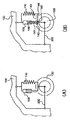
図1(a)に概略が図示された公知の従来サスペンション装置は、平行な衝撃吸収装置100とばね110とを含む。このような衝撃吸収装置は、回転装置120つまり車両の非懸架部分と、車両の懸架部分、例えば車両のボデー130との間に公知の方法で配置される。二輪車では、衝撃吸収装置は、前輪と車両のステアリングコラムとの間の分岐管に配置されるか、車両のボデーと、後輪の車軸を収容する振動アームとの間に取り付けられている。
A known conventional suspension device, schematically illustrated in FIG. 1 (a), includes a parallel shock absorber 100 and a
図1(b)に概略が図示された本発明によるサスペンション装置は、変形された衝撃吸収装置105と、やはり平行に取り付けられているが、この例では上方当接部143と回転装置120に機械的に固定された下方当接部144との間においてばね/衝撃吸収装置アセンブリ105、110に対して可動である部材142を含む接続部材140を介して回転部分120に接続されたばね110とを含み、サスペンション装置はさらに、可動部材142に固定されるとともに衝撃吸収装置105と一体的な排出装置15を制御するのに適したロッド141を含む。
The suspension device according to the present invention schematically shown in FIG. 1B is mounted in parallel with the deformed
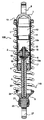
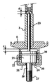
図2により詳しく図示された、本発明による装置の実施例は、ここでは同軸であり、いかなるタイプの車両にも使用可能な衝撃吸収装置105とばね110とを含むサスペンション部材を含む。図示された衝撃吸収装置105は、ピストン2が中で滑動する円筒形キャビティ10を含む衝撃吸収体1を含み、ピストンは、密封リング4を通って円筒形キャビティから突出するピストンロッド3に接続される。衝撃吸収装置105は、用途に応じて一方向または他方向に垂直に取り付けることができる。
The embodiment of the device according to the invention, illustrated in greater detail in FIG. 2, includes a suspension member that includes a
ピストン2は、ピストンによって分離された1つのサブキャビティ10aからサブキャビティ10bへ、ピストンの運動と相関して、油などの流体を通過させるための校正済み手段5を周知のように備え、この運動はサスペンションに印加される力を受けたものである。やはり公知のように、図示された衝撃吸収装置は、不活性ガスが充填されたキャビティ12からキャビティ10を分離する浮動補助ピストン11を含む。
Piston 2 comprises, as is well known, calibrated means 5 for passing a fluid, such as oil, from one subcavity 10a separated by a piston to a
衝撃吸収装置1の本体は、車両の部材つまり車両の回転構造の部材へ衝撃吸収装置を固定する手段8を備えるヘッド7によって、密封リング4と反対側で閉じられている。衝撃吸収装置本体1がピストンロッドの上にある状態で衝撃吸収装置が図示されているこの例では、衝撃吸収装置本体は上方ヘッド7を介して車両のシャシに固着されるのに対して、ピストンロッド3は第1側ではピストン2へ、第2側では、車両の回転構造への接続部材の一部を形成する下方ヘッド6へ接続されている。
The body of the shock absorber 1 is closed on the opposite side of the sealing ring 4 by a head 7 comprising means 8 for fixing the shock absorber to a vehicle member, i.e. a member of the rotating structure of the vehicle. In this example, where the shock absorber body is shown with the shock absorber body 1 on the piston rod, the shock absorber body is secured to the vehicle chassis via the upper head 7, whereas the piston The rod 3 is connected on the first side to the piston 2 and on the second side to a
やはりこの例では、ばね110は衝撃吸収装置と同軸に配置されるとともに、一方は上方ヘッド7に、他方は下方ヘッド6に固定された2つの環状当接部13、14の間で圧縮状態にある。
Again in this example, the
本発明によれば、衝撃吸収装置は、流体を通過させるための校正済み手段5に加えて、ピストン2に接続された排出装置15を含み、この排出装置は、サブキャビティの一方と他方との間において導管16、17の開位置とこの導管の閉位置とを取らせるのに適している。
According to the invention, the shock absorber comprises a discharge device 15 connected to the piston 2 in addition to the calibrated means 5 for passing the fluid, which discharge device is connected to one and the other of the subcavities. Suitable for allowing the
この排出装置は、上方サブキャビティ10bへ開口する第1通路16と、所望であれば複数の分岐路を備えて下方サブキャビティ10aへ開口する第2通路17と、通路16、17の間の通過のための閉口システム18、19とを含む。閉口システムは図のように、第1通路16と第2通路17との間の連通が閉じた時にシート19に嵌着するニードルバルブ18を含み、第1通路16と第2通路17との間の連通が開くと、ニードルバルブ18はシート19から離間する。
The discharge device includes a
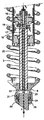
ニードルバルブの制御は、制御ロッド20によって実施される。ピストンロッド3内で軸方向に滑動するこの制御ロッドは、可動体21を終端とし、可動体21は、ヘッド6に設けられた室22に配置されるとともに、可動体21の上面が室22の上壁23と当接する別の当接位置と、室22の底面を閉じる中央通路を備えるねじ付プラグ25によって可動体21が保持される下方当接位置との間で、室22内を滑動するのに適している。図2、図3、図4に図示された実施例によれば、可動体21は、ねじ付プラグ25で構成される室の下壁24と当接する環状リング26´を含む。
The needle valve is controlled by the
このように、回転構造への衝撃吸収装置ロッド3の接続手段は、衝撃吸収装置に対して固着された本体を含み、この固着された本体は、ヘッド6と、衝撃吸収装置に対して可動である本体とを含み、この可動体は、回転構造への固定のための手段27を備える可動体21である。
Thus, the means for connecting the shock absorber rod 3 to the rotating structure includes a body fixed to the shock absorber, which is movable relative to the
ヘッド6と可動体21とは、ばね/衝撃吸収装置アセンブリ105、110に対して可動である部材142を含む接続部材140に対応する。
The
排出装置の動作は以下の通りである。 The operation of the discharge device is as follows.
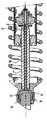
停止時には、車両は回転構造と当接し、こうして可動体は室22を閉じる壁23の間に保持され、ニードルバルブ18はそのシート19に嵌着し、第1および第2通路の間の通過部分が閉じられる。この位置は図4に示されている。
When the vehicle is stopped, the vehicle comes into contact with the rotating structure, and thus the movable body is held between the
車両が動いて適度な運動を受けると、サスペンションは応力を受けた状態にあるため、ばねは圧縮状態または伸張状態にある。この形態では、車両の車輪は地面と接触したままであり、可動体21は室22を閉じる壁23へと保持されたままであり、ニードルバルブ18は依然としてシート19に嵌着し、第1および第2通路の間の通過部分は閉じたままである。
As the vehicle moves and undergoes moderate motion, the suspension is under stress and the spring is in a compressed or extended state. In this configuration, the wheels of the vehicle remain in contact with the ground, the
対照的に、例えば轍に当たった後で衝撃吸収装置が突然伸張した場合には、サスペンションは開放モードに入る。つまり地面と車両の距離の変化がより急激であって、ばねの伸張速度が衝撃吸収装置によって抑制されるのである。このような場合に従来のサスペンションでは、車輪が地面を離れてから、ばねがおそらくまだ伸張していない間に車両が落下する。 In contrast, if the shock absorber stretches suddenly, for example after hitting a heel, the suspension enters an open mode. That is, the change in the distance between the ground and the vehicle is more rapid, and the extension speed of the spring is suppressed by the shock absorbing device. In such cases, conventional suspensions cause the vehicle to fall after the wheel leaves the ground and the spring is probably not yet extended.
逆に、本発明による装置を備えるサスペンションでは、車輪と地面との間の接触が失われると、回転機構が自重によって図3の矢印Fで表された方向に可動体21を下向きに引き、これが制御ロッド20を介してニードルバルブ18をシート19から解離させ、第1および第2排出通路16、17の間の通過部分P1、P2を開いて、キャビティ10aからキャビティ10bへと流体を大量に流出させ、車輪が再び地面と接触するまでばねがより急激に伸張するようにばねを開放する弱い法則へ、衝撃吸収装置105の衝撃吸収法則を変化させる。
On the contrary, in the suspension provided with the device according to the present invention, when the contact between the wheel and the ground is lost, the rotating mechanism pulls the
接触の損失が最少である時には、車輪と地面との接触を回復すると、第1および第2通路の間の通過部分が即座に閉じられる。全地形型車両の場合に例えば轍を通過した後で接触の損失がもっと長く続く時には、サスペンションができる限り速く完全に伸張する。 When contact loss is minimal, restoring the contact between the wheel and the ground immediately closes the passage between the first and second passages. In the case of all-terrain vehicles, for example when the loss of contact lasts longer after passing through a ridge, the suspension is fully extended as quickly as possible.
このように本発明は、サスペンションの開放モードにおいて、負荷を受けている衝撃吸収法則と負荷が低下した衝撃吸収法則との間で選択できる衝撃吸収制御を提供できる。 In this way, the present invention can provide shock absorption control that can be selected between the shock absorption law under load and the shock absorption law with reduced load in the suspension release mode.
装置の動作は、可動体21の運動に左右される。すでに分かっているように、ねじ付プラグ25は、サスペンションが伸張する時に可動体21を保持するとともに、衝撃吸収装置が上向き位置である衝撃吸収装置の場合には車両の回転構造との、あるいは逆転した衝撃吸収装置の場合には車両のボデーとの固定手段27を含む可動体21の部分を通過させる。
The operation of the apparatus depends on the movement of the
可動体21が延出している図5に図示された例では、ねじ付プラグは、可動体21の表面と直接に相互作用を行って下方向への可動体21の自由運動の可能性を制限する環状底面24を含む。この例では、固定手段27を備えて断面積が狭くなった終端ロッド29を可動体21が含む。
In the example illustrated in FIG. 5 where the
室22を閉じるのにねじ付プラグを使用すると、ねじ付プラグ25の把持に作用することによって、可動体21の開放経路を調整し、結果的にニードルバルブ18の経路“d”を調整する。
When a threaded plug is used to close the
この原則によれば、サスペンションの開放モードに対応する延出位置における可動体21の最大移動距離を変更することにより、そしてニードルバルブ18の最大移動を調整することにより、排出装置における流体通過の流速を適応させることが可能である。
According to this principle, by changing the maximum moving distance of the
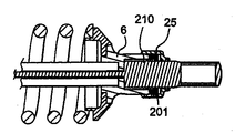
本発明による装置は、補正手段を追加することによって改良でき、特に図7には、リング210によって可動体21に固定されるとともにねじ付プラグ25と当接するらせんばねの形の補正装置201が可動体21と衝撃吸収体1との間に位置する実施例が開示されており、補正装置は、可動体を押し上げることにより、導管の開位置における排出装置の移動に抵抗する。この原則によれば、ばね201の剛性が低い場合には導管の開口の遅れが生じ、ばねの剛性が高い場合には、伸張時の突然の衝撃のみが通路の開口を引き起こす。
The device according to the invention can be improved by adding correction means, in particular in FIG. 7 the
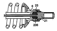
対照的に図8の例は、補正装置が導管の開口を促進する例である。この例では、可動体21と衝撃吸収体1との間にらせんばねの形の補正部材206も位置しているが、この時、らせんばねは、可動体21のヘッドと衝撃吸収体のヘッド6の底部との間に配置されている。
In contrast, the example of FIG. 8 is an example where the correction device facilitates opening of the conduit. In this example, a
この原則によれば、衝撃吸収装置が開放されるとすぐに、補正装置206が導管の開位置への排出装置の移動を促進し、衝撃吸収装置を完全にフリーモードへ移動させることがない。
According to this principle, as soon as the shock absorber is opened, the
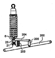
一般的に、振動アーム200またはロッドは、車両の非懸架部分120と車両の懸架部分130とを接続する。図9の例では、補正装置はレバー204とばね203とによって構成され、レバー204の第1端部はヘッド6において衝撃吸収体1に、第2端部は振動アーム200に関節接続されたアーム205に固着されている。
Generally, the vibrating
ばね203は、振動アームとロッドとの間に配置される。つまり最終的には、振動アームに固着された可動体21と衝撃吸収装置の本体1との間にヘッド6を介して配置される。
The
こうして、ばね203は可動体21と衝撃吸収体1との間に分離力を印加し、この力は、衝撃吸収装置が開放されるか、車輪が地面を離れる時に、導管の開位置への排出装置の移動を促進する。
Thus, the
本発明によるシステムが、ロッド3が上向きで衝撃吸収装置本体1が下向きである逆転衝撃吸収装置としても機能することに注意すべきである。ゆえにこのような構成では、移動するのは、車両のシャシに固着された可動体21ではなく、地面を離れる時の車輪の運動に従う衝撃吸収装置アセンブリのばねである。ゆえに、ヘッド6が上方ヘッドとなる時には、可動体21が同様に変化し、当接部23(この場合には可動体21の下方当接部)から離れ、通路16、17の間の通過部分を開放して、排出回路を開く。
It should be noted that the system according to the invention also functions as a reverse shock absorber with the rod 3 facing up and the shock absorber body 1 facing down. Therefore, in such a configuration, it is not the
このシステムの動作では、衝撃吸収装置とばねとが同軸である必要はもはやないが、排出装置を開口させる可動体は、ばね/衝撃吸収装置アセンブリの外側に残すべきである。 In operation of this system, the shock absorber and the spring no longer need to be coaxial, but the movable body that opens the ejector should remain outside the spring / shock absorber assembly.
1 衝撃吸収装置本体
2 ピストン
3 ピストンロッド
4 密封リング
5 校正済み手段
6 下方ヘッド
7 上方ヘッド
10 キャビティ
10a 下方キャビティ
10b 上方キャビティ
11 浮動補助ピストン
12 不活性ガスキャビティ
13 環状当接部
16 導管/第1通路
17 導管/第2通路
18 ニードルバルブ
19 シート
20 制御ロッド
21 可動体
23 当接部
24 室の下壁
25 ねじ付プラグ
26´ 環状リング
27 固定手段
29 終端ロッド
100 衝撃吸収装置
105 衝撃吸収装置
110 ばね
120 非懸架部分/回転装置
130 懸架部分/車両ボデー
140 接続部材
141 ロッド
143 上方当接部
144 下方当接部
DESCRIPTION OF SYMBOLS 1 Shock absorber main body 2 Piston 3 Piston rod 4 Sealing ring 5 Calibrated means 6 Lower head 7
Claims (12)
A vibration arm (200) connects the non-suspended portion (120) of the vehicle and the suspended portion (130) of the vehicle, and at one end to the shock absorber (1) and to the vibration arm (200). A correction member comprising a rod (204) secured by a second end to an articulated arm (205) and a spring (203) disposed between the vibrating arm and the rod is provided in the conduit. The separation force for promoting the movement of the discharging device to the open position is applied between the movable body (21) and the shock absorber (1). The device described in the paragraph.
Applications Claiming Priority (1)
| Application Number | Priority Date | Filing Date | Title |
|---|---|---|---|
| FR0450636A FR2868493B1 (en) | 2004-03-31 | 2004-03-31 | SUSPENSION DEVICE WITH HYDRAULIC SHOCK ABSORBER WITH SELECTIVE DAMPING CONTROL |
Publications (1)
| Publication Number | Publication Date |
|---|---|
| JP2005291491A true JP2005291491A (en) | 2005-10-20 |
Family
ID=34947544
Family Applications (1)
| Application Number | Title | Priority Date | Filing Date |
|---|---|---|---|
| JP2004324384A Pending JP2005291491A (en) | 2004-03-31 | 2004-11-08 | Suspension device having hydraulic shock-absorbing device to effect selective shock absorbing control |
Country Status (3)
| Country | Link |
|---|---|
| US (1) | US20050217953A1 (en) |
| JP (1) | JP2005291491A (en) |
| FR (1) | FR2868493B1 (en) |
Cited By (1)
| Publication number | Priority date | Publication date | Assignee | Title |
|---|---|---|---|---|
| WO2011080795A1 (en) * | 2009-12-28 | 2011-07-07 | 株式会社テイン | Suspension device |
Families Citing this family (18)
| Publication number | Priority date | Publication date | Assignee | Title |
|---|---|---|---|---|
| FR2897915B1 (en) * | 2006-02-27 | 2008-05-30 | Bos Sarl | QUICK-RISE DAMPING SYSTEM MOUNTED TO FORCE LEG |
| CA2801334C (en) | 2010-06-03 | 2020-03-10 | Polaris Industries Inc. | Electronic throttle control |
| US9205717B2 (en) | 2012-11-07 | 2015-12-08 | Polaris Industries Inc. | Vehicle having suspension with continuous damping control |
| FR3003619B1 (en) * | 2013-03-25 | 2015-03-27 | Peugeot Citroen Automobiles Sa | HYDRAULIC SHOCK ABSORBER COMPRISING A FAST RELIEF DEVICE |
| US10648554B2 (en) | 2014-09-02 | 2020-05-12 | Polaris Industries Inc. | Continuously variable transmission |
| CN107406094B (en) | 2014-10-31 | 2020-04-14 | 北极星工业有限公司 | System and method for controlling a vehicle |
| DE102016209826A1 (en) * | 2016-06-03 | 2017-12-07 | Suspa Gmbh | damper |
| CA3043481C (en) | 2016-11-18 | 2022-07-26 | Polaris Industries Inc. | Vehicle having adjustable suspension |
| US10406884B2 (en) | 2017-06-09 | 2019-09-10 | Polaris Industries Inc. | Adjustable vehicle suspension system |
| MX2020009417A (en) | 2018-03-19 | 2020-10-05 | Polaris Inc | CONTINUOUSLY VARIABLE TRANSMISSION. |
| JP7059791B2 (en) * | 2018-05-16 | 2022-04-26 | トヨタ自動車株式会社 | Damping force control device |
| US10987987B2 (en) | 2018-11-21 | 2021-04-27 | Polaris Industries Inc. | Vehicle having adjustable compression and rebound damping |
| US12397878B2 (en) | 2020-05-20 | 2025-08-26 | Polaris Industries Inc. | Systems and methods of adjustable suspensions for off-road recreational vehicles |
| MX2022015902A (en) | 2020-07-17 | 2023-01-24 | Polaris Inc | Adjustable suspensions and vehicle operation for off-road recreational vehicles. |
| CN112677912A (en) * | 2021-01-06 | 2021-04-20 | 恒大新能源汽车投资控股集团有限公司 | Automobile, anti-rolling device and anti-rolling method |
| US12504070B2 (en) | 2021-01-29 | 2025-12-23 | Polaris Industries Inc. | Electronically-controlled continuously variable transmission for a utility vehicle |
| CN112918203B (en) * | 2021-03-10 | 2023-03-17 | 奈克斯科技股份有限公司 | Active telescopic shock absorber of rail dual-purpose vehicle and vehicle suspension and switching method |
| CN113202895A (en) * | 2021-03-23 | 2021-08-03 | 济南弗莱德科学仪器有限公司 | Oil product quick-inspection vehicle damping device |
Citations (4)
| Publication number | Priority date | Publication date | Assignee | Title |
|---|---|---|---|---|
| FR2796431A1 (en) * | 1999-07-16 | 2001-01-19 | Nicolas Carlier | Oil-filled shock absorber has piston with passage connecting upper and lower sections of cylinder and spring at bottom, passage being shut when weight supported by spring and force of reaction of ground are large and open when small |
| JP2002005219A (en) * | 2000-06-21 | 2002-01-09 | Mitsubishi Motors Corp | Vehicle shock absorber |
| JP2002161939A (en) * | 2000-11-24 | 2002-06-07 | Parts Creator Kk | Shock absorber |
| JP2002240527A (en) * | 2001-02-19 | 2002-08-28 | Tein:Kk | Apparatus for adjusting damping force of shock absorber for vehicle and method of providing control program therefor |
Family Cites Families (10)
| Publication number | Priority date | Publication date | Assignee | Title |
|---|---|---|---|---|
| US3272493A (en) * | 1964-08-26 | 1966-09-13 | Bourcier Christian Marie Louis | Shock absorbers |
| NL6817259A (en) * | 1968-12-03 | 1970-06-05 | ||
| DE2249971A1 (en) * | 1972-10-12 | 1974-04-18 | Daimler Benz Ag | SUSPENSION OF STEERABLE VEHICLE WHEELS, IN PARTICULAR FRONT WHEELS OF MOTOR VEHICLES |
| US4305486A (en) * | 1979-10-11 | 1981-12-15 | Interpart Corporation | Dual damping control valve shock absorber |
| US5178242A (en) | 1990-11-19 | 1993-01-12 | Atsugi Unisia Corporation | Hydraulic damper |
| US6244398B1 (en) * | 1997-05-15 | 2001-06-12 | K2 Bike Inc. | Shock absorber with variable bypass damping |
| US6161662A (en) * | 1999-03-16 | 2000-12-19 | Delphi Technologies, Inc. | Suspension damper for motor vehicle |
| US6382370B1 (en) * | 1999-09-01 | 2002-05-07 | K2 Bike, Inc. | Shock absorber with an adjustable lock-out value and two-stage flow restriction |
| DE10122729B4 (en) * | 2001-05-10 | 2006-04-20 | Dt Swiss Ag | Spring damper system for bicycles |
| FR2851808B1 (en) * | 2002-10-25 | 2006-09-29 | Amortisseur Donerre | HYDRAULIC SHOCK ABSORBER FOR VEHICLE, SHOCK ABSORBER SYSTEM AND METHOD OF USE |
-
2004
- 2004-03-31 FR FR0450636A patent/FR2868493B1/en not_active Expired - Fee Related
- 2004-11-04 US US10/980,427 patent/US20050217953A1/en not_active Abandoned
- 2004-11-08 JP JP2004324384A patent/JP2005291491A/en active Pending
Patent Citations (4)
| Publication number | Priority date | Publication date | Assignee | Title |
|---|---|---|---|---|
| FR2796431A1 (en) * | 1999-07-16 | 2001-01-19 | Nicolas Carlier | Oil-filled shock absorber has piston with passage connecting upper and lower sections of cylinder and spring at bottom, passage being shut when weight supported by spring and force of reaction of ground are large and open when small |
| JP2002005219A (en) * | 2000-06-21 | 2002-01-09 | Mitsubishi Motors Corp | Vehicle shock absorber |
| JP2002161939A (en) * | 2000-11-24 | 2002-06-07 | Parts Creator Kk | Shock absorber |
| JP2002240527A (en) * | 2001-02-19 | 2002-08-28 | Tein:Kk | Apparatus for adjusting damping force of shock absorber for vehicle and method of providing control program therefor |
Cited By (1)
| Publication number | Priority date | Publication date | Assignee | Title |
|---|---|---|---|---|
| WO2011080795A1 (en) * | 2009-12-28 | 2011-07-07 | 株式会社テイン | Suspension device |
Also Published As
| Publication number | Publication date |
|---|---|
| FR2868493A1 (en) | 2005-10-07 |
| US20050217953A1 (en) | 2005-10-06 |
| FR2868493B1 (en) | 2008-06-13 |
Similar Documents
| Publication | Publication Date | Title |
|---|---|---|
| JP2005291491A (en) | Suspension device having hydraulic shock-absorbing device to effect selective shock absorbing control | |
| US7441638B2 (en) | Front fork | |
| US9731575B2 (en) | Suspension apparatus | |
| EP1158200B1 (en) | Air spring | |
| CN100363226C (en) | motorcycle steering damper | |
| CN105313627B (en) | Vehicles with bumpers | |
| EP2487384B1 (en) | Hydraulic shock absorbing device | |
| US9855811B2 (en) | Vehicle suspension system | |
| JPS5981290A (en) | Attitude controller on braking of motorcycle | |
| EP1880880B1 (en) | Vehicle | |
| CN1965174A (en) | Electronically controlled frequency dependent damping | |
| JPH11315876A (en) | Damper | |
| JP4918022B2 (en) | Damping force adjustment structure of hydraulic shock absorber | |
| JP4637409B2 (en) | Front fork | |
| JP4800172B2 (en) | Motorcycle | |
| TWI845691B (en) | Rolling motor vehicle with tilt-blocking system acting on the shock absorber | |
| US20030094341A1 (en) | Shock absorber with a gas chamber on the rebound side of a piston | |
| JPS59179413A (en) | Shock absorber | |
| JPH11280826A (en) | Front fork | |
| WO2019014726A1 (en) | Suspension damping system | |
| JP2006151161A (en) | Air spring and suspension | |
| JP4842012B2 (en) | vehicle | |
| JP3938411B2 (en) | Hydraulic shock absorber | |
| JP2001082529A (en) | Suspension devices for motorcycles, etc. | |
| JP2001099214A (en) | Hydraulic shock absorber |
Legal Events
| Date | Code | Title | Description |
|---|---|---|---|
| A621 | Written request for application examination |
Free format text: JAPANESE INTERMEDIATE CODE: A621 Effective date: 20071029 |
|
| A977 | Report on retrieval |
Free format text: JAPANESE INTERMEDIATE CODE: A971007 Effective date: 20100914 |
|
| A131 | Notification of reasons for refusal |
Free format text: JAPANESE INTERMEDIATE CODE: A131 Effective date: 20100929 |
|
| A601 | Written request for extension of time |
Free format text: JAPANESE INTERMEDIATE CODE: A601 Effective date: 20101228 |
|
| A602 | Written permission of extension of time |
Free format text: JAPANESE INTERMEDIATE CODE: A602 Effective date: 20110106 |
|
| A02 | Decision of refusal |
Free format text: JAPANESE INTERMEDIATE CODE: A02 Effective date: 20110329 |