JP2005291489A - Bearing device for wheel - Google Patents
Bearing device for wheel Download PDFInfo
- Publication number
- JP2005291489A JP2005291489A JP2004263740A JP2004263740A JP2005291489A JP 2005291489 A JP2005291489 A JP 2005291489A JP 2004263740 A JP2004263740 A JP 2004263740A JP 2004263740 A JP2004263740 A JP 2004263740A JP 2005291489 A JP2005291489 A JP 2005291489A
- Authority
- JP
- Japan
- Prior art keywords
- encoder
- inner member
- bearing device
- wheel bearing
- wheel
- Prior art date
- Legal status (The legal status is an assumption and is not a legal conclusion. Google has not performed a legal analysis and makes no representation as to the accuracy of the status listed.)
- Pending
Links
- 238000005096 rolling process Methods 0.000 claims abstract description 11
- 239000002184 metal Substances 0.000 claims description 14
- 238000001514 detection method Methods 0.000 description 7
- 230000000452 restraining effect Effects 0.000 description 7
- 238000004519 manufacturing process Methods 0.000 description 4
- 230000005489 elastic deformation Effects 0.000 description 3
- 238000003825 pressing Methods 0.000 description 3
- 238000000034 method Methods 0.000 description 2
- 238000007789 sealing Methods 0.000 description 2
- 239000000725 suspension Substances 0.000 description 2
- 230000000694 effects Effects 0.000 description 1
- 238000003780 insertion Methods 0.000 description 1
- 230000037431 insertion Effects 0.000 description 1
- 239000000463 material Substances 0.000 description 1
- 230000002093 peripheral effect Effects 0.000 description 1
- 239000011347 resin Substances 0.000 description 1
- 229920005989 resin Polymers 0.000 description 1
- 229910001220 stainless steel Inorganic materials 0.000 description 1
- 239000010935 stainless steel Substances 0.000 description 1
- 238000004073 vulcanization Methods 0.000 description 1
Images


Classifications
-
- F—MECHANICAL ENGINEERING; LIGHTING; HEATING; WEAPONS; BLASTING
- F16—ENGINEERING ELEMENTS AND UNITS; GENERAL MEASURES FOR PRODUCING AND MAINTAINING EFFECTIVE FUNCTIONING OF MACHINES OR INSTALLATIONS; THERMAL INSULATION IN GENERAL
- F16C—SHAFTS; FLEXIBLE SHAFTS; ELEMENTS OR CRANKSHAFT MECHANISMS; ROTARY BODIES OTHER THAN GEARING ELEMENTS; BEARINGS
- F16C41/00—Other accessories, e.g. devices integrated in the bearing not relating to the bearing function as such
- F16C41/007—Encoders, e.g. parts with a plurality of alternating magnetic poles
-
- F—MECHANICAL ENGINEERING; LIGHTING; HEATING; WEAPONS; BLASTING
- F16—ENGINEERING ELEMENTS AND UNITS; GENERAL MEASURES FOR PRODUCING AND MAINTAINING EFFECTIVE FUNCTIONING OF MACHINES OR INSTALLATIONS; THERMAL INSULATION IN GENERAL
- F16C—SHAFTS; FLEXIBLE SHAFTS; ELEMENTS OR CRANKSHAFT MECHANISMS; ROTARY BODIES OTHER THAN GEARING ELEMENTS; BEARINGS
- F16C33/00—Parts of bearings; Special methods for making bearings or parts thereof
- F16C33/72—Sealings
- F16C33/76—Sealings of ball or roller bearings
- F16C33/78—Sealings of ball or roller bearings with a diaphragm, disc, or ring, with or without resilient members
- F16C33/7803—Sealings of ball or roller bearings with a diaphragm, disc, or ring, with or without resilient members suited for particular types of rolling bearings
- F16C33/7813—Sealings of ball or roller bearings with a diaphragm, disc, or ring, with or without resilient members suited for particular types of rolling bearings for tapered roller bearings
-
- F—MECHANICAL ENGINEERING; LIGHTING; HEATING; WEAPONS; BLASTING
- F16—ENGINEERING ELEMENTS AND UNITS; GENERAL MEASURES FOR PRODUCING AND MAINTAINING EFFECTIVE FUNCTIONING OF MACHINES OR INSTALLATIONS; THERMAL INSULATION IN GENERAL
- F16C—SHAFTS; FLEXIBLE SHAFTS; ELEMENTS OR CRANKSHAFT MECHANISMS; ROTARY BODIES OTHER THAN GEARING ELEMENTS; BEARINGS
- F16C19/00—Bearings with rolling contact, for exclusively rotary movement
- F16C19/22—Bearings with rolling contact, for exclusively rotary movement with bearing rollers essentially of the same size in one or more circular rows, e.g. needle bearings
- F16C19/34—Bearings with rolling contact, for exclusively rotary movement with bearing rollers essentially of the same size in one or more circular rows, e.g. needle bearings for both radial and axial load
- F16C19/38—Bearings with rolling contact, for exclusively rotary movement with bearing rollers essentially of the same size in one or more circular rows, e.g. needle bearings for both radial and axial load with two or more rows of rollers
- F16C19/383—Bearings with rolling contact, for exclusively rotary movement with bearing rollers essentially of the same size in one or more circular rows, e.g. needle bearings for both radial and axial load with two or more rows of rollers with tapered rollers, i.e. rollers having essentially the shape of a truncated cone
- F16C19/385—Bearings with rolling contact, for exclusively rotary movement with bearing rollers essentially of the same size in one or more circular rows, e.g. needle bearings for both radial and axial load with two or more rows of rollers with tapered rollers, i.e. rollers having essentially the shape of a truncated cone with two rows, i.e. double-row tapered roller bearings
- F16C19/386—Bearings with rolling contact, for exclusively rotary movement with bearing rollers essentially of the same size in one or more circular rows, e.g. needle bearings for both radial and axial load with two or more rows of rollers with tapered rollers, i.e. rollers having essentially the shape of a truncated cone with two rows, i.e. double-row tapered roller bearings in O-arrangement
-
- F—MECHANICAL ENGINEERING; LIGHTING; HEATING; WEAPONS; BLASTING
- F16—ENGINEERING ELEMENTS AND UNITS; GENERAL MEASURES FOR PRODUCING AND MAINTAINING EFFECTIVE FUNCTIONING OF MACHINES OR INSTALLATIONS; THERMAL INSULATION IN GENERAL
- F16C—SHAFTS; FLEXIBLE SHAFTS; ELEMENTS OR CRANKSHAFT MECHANISMS; ROTARY BODIES OTHER THAN GEARING ELEMENTS; BEARINGS
- F16C2326/00—Articles relating to transporting
- F16C2326/01—Parts of vehicles in general
- F16C2326/02—Wheel hubs or castors
-
- F—MECHANICAL ENGINEERING; LIGHTING; HEATING; WEAPONS; BLASTING
- F16—ENGINEERING ELEMENTS AND UNITS; GENERAL MEASURES FOR PRODUCING AND MAINTAINING EFFECTIVE FUNCTIONING OF MACHINES OR INSTALLATIONS; THERMAL INSULATION IN GENERAL
- F16C—SHAFTS; FLEXIBLE SHAFTS; ELEMENTS OR CRANKSHAFT MECHANISMS; ROTARY BODIES OTHER THAN GEARING ELEMENTS; BEARINGS
- F16C33/00—Parts of bearings; Special methods for making bearings or parts thereof
- F16C33/30—Parts of ball or roller bearings
- F16C33/58—Raceways; Race rings
- F16C33/583—Details of specific parts of races
Landscapes
- Engineering & Computer Science (AREA)
- General Engineering & Computer Science (AREA)
- Mechanical Engineering (AREA)
- Rolling Contact Bearings (AREA)
Abstract
Description
この発明は、アンチロックブレーキ装置を備えた自動車等に用いられる回転センサ内蔵の車輪用軸受装置に関する。 The present invention relates to a wheel bearing device with a built-in rotation sensor used in an automobile or the like equipped with an antilock brake device.
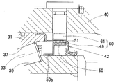
アンチロックブレーキ装置(ABS)は、低摩擦路やパニックブレーキ時のタイヤロックを検知し、ブレーキを緩めてタイヤグリップを確保することで、操舵安定性を得るものである。タイヤロックを検知する車輪回転数のセンサは、車輪用軸受装置に設けられる。 センサ内蔵の車輪用軸受装置として、従来、図5に示すように、内周に複列の軌道面36,37を有する外方部材31と、これら軌道面36,37にそれぞれ対向する軌道面38,39を有する内方部材32と、前記各軌道面36〜39間に介在する複列の転動体33とで構成され、外方部材31と内方部材32間の一端部に回転センサ60を設置したものが提案されている(例えば特許文献1)。
The anti-lock brake device (ABS) obtains steering stability by detecting a tire lock during a low friction road or a panic brake, and securing a tire grip by releasing the brake. A wheel rotational speed sensor for detecting tire lock is provided in the wheel bearing device. As a wheel bearing device with a built-in sensor, conventionally, as shown in FIG. 5, an
外付部材31は外周部が車体の懸架装置におけるナックル40に取付けられ、内方部材32の一端のフランジ32aに車輪が取付けられる。外方部材31と内方部材32間にできる環状空間の両端部はそれぞれシール部材41,42でシールされる。回転センサ60は、回転側の内方部材32に回転被検出部である環状のエンコーダ49を装着し、固定側の外方部材31を設置したナックル40に、回転検出部である磁気センサ61を上記エンコーダ49と対向して装着することにより構成されている。エンコーダ49と磁気センサ61の間には、シール部材42の芯金が介在する。図6は図5におけるエンコーダ49が取付けられるA部の拡大図を示し、図7はそのエンコーダ49の断面図を示す。磁気センサ61としては、ホール素子やホールICなどが使用される。
The
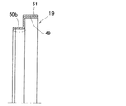
上記エンコーダ49は、環状の芯金50に、円周方向に磁気特性が変化する環状の多極磁石51を設けたものであり、内方部材32の外周に上記芯金50を嵌合させることにより、エンコーダ49が内方部材32に装着される。具体的には、内方部材32は、ハブ輪45と、このハブ輪45の軸部外周に嵌合される一対の分割型の内輪46A,46Bとでなり、インボード側の内輪46Bの外周に上記芯金50を嵌合させている。
しかし、上記構成の回転センサ内蔵の車輪用軸受装置では、内方部材32の外周に嵌着するエンコーダ49の芯金50の嵌合部50bが、図7に鎖線で囲んで示すように、内周面の滑らかな円筒状とされており、その芯金50が嵌合する内方部材内輪46Bの外周面も滑らかな円筒面とされている。そのため、締代のみで芯金50が内方部材32の内輪46Bに固定されていることになる。その結果、荷重変動により内輪46Bに弾性変形が生じた場合、その弾性変形の影響を受けて、エンコーダ49が軸方向に移動することがあり、回転検出の精度低下を招く恐れがある。また、上記締代を大きくすることで、エンコーダ49の軸方向への移動を抑制しようとすると、エンコーダ49の芯金50が塑性変形域に達してしまい、かえって嵌合の効果が得られない場合もある。
However, in the wheel bearing device with a built-in rotation sensor configured as described above, the
この発明の目的は、回転被検出部となるエンコーダの内方部材への嵌合が確実なものとなり、エンコーダの軸方向への移動を抑制できる回転センサ内蔵の車輪用軸受装置を提供することである。 SUMMARY OF THE INVENTION An object of the present invention is to provide a wheel bearing device with a built-in rotation sensor that can be reliably fitted to an inner member of an encoder serving as a rotation detected portion and can suppress the movement of the encoder in the axial direction. is there.
この発明の車輪用軸受装置は、内周に複列の軌道面を有する外方部材と、これら軌道面に対向する軌道面を有する内方部材と、対向する軌道面間に介在した複列の転動体とを備え、車体に対して車輪を回転自在に支持する車輪用軸受装置において、内方部材のインボード側の端部の外周に、回転被検出部となる環状のエンコーダを嵌合させ、このエンコーダと内方部材との間に、引っ掛かりにより軸方向の移動抑制を行う抜け止め手段を設けたことを特徴とする。
この構成によると、内方部材の外周に嵌合されるエンコーダは、エンコーダと内方部材との間に設けられた抜け止め手段で引っ掛かりにより移動抑制されているため、荷重変動により内方部材の内輪に弾性変形が生じても、エンコーダが軸方向に移動することを抑制できる。そのため、軸方向移動により回転検出精度が低下することを防止できる。
The wheel bearing device of the present invention comprises an outer member having a double-row raceway surface on the inner periphery, an inner member having a raceway surface facing these raceway surfaces, and a double-row interposed between the opposing raceway surfaces. In a wheel bearing device including a rolling element and rotatably supporting a wheel with respect to a vehicle body, an annular encoder serving as a rotation detected portion is fitted to an outer periphery of an end portion on an inboard side of an inner member. Further, it is characterized in that a retaining means is provided between the encoder and the inner member to restrain axial movement by being caught.
According to this configuration, the encoder fitted to the outer periphery of the inner member is restrained from moving by being caught by the retaining means provided between the encoder and the inner member. Even if elastic deformation occurs in the inner ring, the encoder can be prevented from moving in the axial direction. Therefore, it is possible to prevent the rotation detection accuracy from being lowered due to the axial movement.
前記抜け止め手段は引っ掛かりによって抜け止めを行うものであるため、前記エンコーダと内方部材との嵌合に締代を持たせることで、締代による移動抑制力に引っ掛かりによる移動抑制力が加わることになる。このため、より大きな軸方向移動力に耐えることができる。また、引っ掛かりによる抜け止め手段だけで大きな移動抑制力を与える場合に比べて、抜け止め手段が無理なく簡素なものに形成できる。 Since the retaining means is for retaining by catching, by providing a tightening allowance for the engagement between the encoder and the inner member, a movement restraining force due to the catch is added to the movement restraining force due to the tightening allowance. become. For this reason, it can endure a larger axial movement force. In addition, the retaining means can be formed to be simple and simple as compared with a case where a large movement restraining force is applied only by the retaining means by catching.
この発明において、前記エンコーダが、内方部材の外周に嵌合する環状の芯金に、円周方向に磁気特性が変化する環状の磁石を設けたものであり、前記抜け止め手段を前記芯金と内方部材との間に設けたものであっても良い。芯金を利用すると、引っ掛かり形式の抜け止め手段が容易に形成できる。 In this invention, the encoder is provided with an annular magnet whose magnetic characteristics change in a circumferential direction on an annular cored bar fitted to the outer periphery of the inner member, and the retaining means is the cored bar. And between the inner member and the inner member. When the cored bar is used, a catching type retaining means can be easily formed.
芯金を利用する場合に、前記抜け止め手段は、エンコーダ芯金の内方部材嵌合部に設けられた任意個数の内向き突起と、この内向き突起に対応して内方部材に設けられた係合溝とからなるものとしても良い。
芯金を利用する場合、突起の形成が容易に行え、また内方部材は係合溝を設けるだけで良いため、引っ掛かり形式の抜け止め手段が容易に加工できる。
When using a cored bar, the retaining means is provided on the inner member corresponding to the inward projection of any number of inward projections provided on the inner member fitting portion of the encoder cored bar. It is good also as what consists of an engaging groove.
When using the cored bar, the projection can be easily formed, and the inner member only needs to be provided with the engaging groove, so that the hook-type retaining means can be easily processed.
前記内向き突起は、エンコーダ芯金に形成された切起し片であっても良い。前記切起し片は、内方部材の軸方向中央側が基端とされ、端部側へ斜め内径側に延びるものであっても良い。
内向き突起が切起し片であると、プレス加工により成形可能で加工が簡単である。そのため、エンコーダ芯金の一連の製作工程内で、安価に、かつ容易に前記内向き突起を製作でき、また任意個数の内向き突起が製作できる。この切起し片からなる内向き突起は、端部側へ斜め内径側に延びているため、その方向性により、エンコーダの内方部材への嵌合作業が容易で、抜け止め作用は強く得られる。
The inward projection may be a cut and raised piece formed on the encoder core. The cut and raised piece may have a base end in the axial direction center side of the inner member and extend obliquely toward the inner diameter side toward the end side.
If the inward projection is a cut and raised piece, it can be formed by pressing and is easy to process. Therefore, the inward projections can be manufactured inexpensively and easily in a series of manufacturing steps of the encoder core bar, and an arbitrary number of inward projections can be manufactured. Since the inward projection made up of the cut and raised pieces extends toward the end side toward the inner diameter side, the directionality of the inward projection makes it easy to fit the encoder into the inner member and provides a strong retaining action. It is done.
前記内向き突起は、エンコーダ芯金にプレス加工されたエンボス状のものであっても良い。この場合も、プレス加工で成形可能であり、エンコーダ芯金の一連の製作工程内で、安価に、かつ任意個数の内向き突起を容易に製作することができる。 The inward projection may be an embossed shape that is pressed into an encoder core. Also in this case, it can be formed by press working, and an arbitrary number of inward projections can be easily manufactured at low cost within a series of manufacturing steps of the encoder core.
この発明の車輪用軸受装置は、内周に複列の軌道面を有する外方部材と、これら軌道面に対向する軌道面を有する内方部材と、対向する軌道面間に介在した複列の転動体とを備え、車体に対して車輪を回転自在に支持する車輪用軸受装置において、内方部材のインボード側の端部の外周に、回転被検出部となる環状のエンコーダを嵌合させ、このエンコーダと内方部材との間に、引っ掛かりにより軸方向の移動抑制を行う抜け止め手段を設けたため、回転被検出部となるエンコーダの内方部材への嵌合が確実なものとなり、エンコーダの軸方向への移動を抑制できる。 The wheel bearing device of the present invention includes an outer member having a double-row raceway surface on the inner periphery, an inner member having a raceway surface facing these raceway surfaces, and a double-row interposed between the opposing raceway surfaces. In a wheel bearing device including a rolling element and rotatably supporting a wheel with respect to a vehicle body, an annular encoder serving as a rotation detected portion is fitted to an outer periphery of an end portion on an inboard side of an inner member. Since the retaining means for restraining the movement in the axial direction by being caught is provided between the encoder and the inner member, the encoder to be the rotation detected portion can be securely fitted to the inner member. Can be prevented from moving in the axial direction.
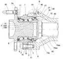
この発明の第1の実施形態を図1ないし図3と共に説明する。この車輪用軸受装置は、ハブユニット形式でかつ複列円すいころ軸受形式としたものであり、いわゆる2.5世代のものである。この車輪用軸受装置は、図1に示すように、複列の軌道面6,7を内周に有する外方部材1と、この軌道面6,7に対向する複列の軌道面8,9を外周に有する内方部材2と、これら軌道面6〜9間に介在した転動体3とを備える。
外方部材1は、固定側の部材となるものであって、外周に車体取付フランジ1bを有する一体の部材である。外方部材1は、車体の懸架装置を構成するナックル40の内径孔に嵌合し、上記車体取付フランジ1bに設けられたボルト挿通孔を貫通するボルト41でナックル40に取付けられている。
A first embodiment of the present invention will be described with reference to FIGS. This wheel bearing device is a hub unit type and a double row tapered roller bearing type, and is of the so-called 2.5 generation. As shown in FIG. 1, the wheel bearing device includes an
The
内方部材2は、車輪取付フランジ2aを有し、この車輪取付フランジ2aに車輪(図示せず)がボルト42で取付けられる。この車輪用軸受装置は、複列の円すいころ軸受とされ、背面合わせとなるように各軌道面6〜9の接触角が形成されている。円すいころからなる転動体3は各列毎に保持器10で保持されている。アウトボード側の転動体3の外側、およびインボード側の転動体3の内側において、外方部材1と内方部材2との間の環状空間がシール部材11,12によりシールされている。この明細書において、アウトボード側とは、車輪用軸受装置を車両に取付けた状態で、車両幅方向の外側となる側を言い、中央側となる側をインボード側と言う。
The
内方部材2は、車輪取付フランジ2aを一体に有するハブ輪15と、前記各転動体列の軌道面8,9がそれぞれ形成された一対の分割型の内輪16A,16Bとで構成される。内輪16A,16Bはハブ輪15の軸部15aの外周に嵌合される。軸部15aは、インボード側に延びる延出部15aaを有している。この延出部15aaに設けられた雄ねじ部15abにナット43をねじ込むことにより、上記内輪16A,16Bが、ハブ輪15の車体取付フランジ2aの基端付近の段面とナット43との間で軸方向に締め付け固定される。
The
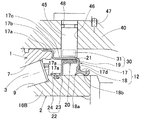
図1のB部を拡大して図2に示す。同図のようにインボード側のシール部材12は、環状の芯金17と、この芯金17の一端部に加硫接着等で固定された弾性部材18とで構成される。シール部材12は、芯金17の圧入円筒部17aで、外方部材1の外周に圧入嵌合される。これにより、磁気エンコーダ19側の軸受端部が、磁気エンコーダ19を覆うようにシール部材12で密封される。芯金17は、上記圧入用円筒部17aに、これよりも小径のカバー用円筒部17cが第1の立板部17bを介して続き、カバー用円筒部17cの先端から内径側へ第2の立板部17dが延びた形状のものである。第2の立板部17dの先端に、上記弾性体18が取付けられている。弾性部材18は複数のリップ部18a,18bを有し、これらリップ部18a,18bを上記内輪16Bの外周に摺接させることで、内外部材2,1間のインボード側端部がシールされる。
The B part of FIG. 1 is expanded and shown in FIG. As shown in the figure, the
この車輪用軸受装置に設けられる回転センサ30は、回転被検出部となる環状のエンコーダ19と、検出部となる磁気センサ31とで構成される。これらエンコーダ19と磁気センサ31とは、シール部材12の芯金17のカバー用円筒部17cを介して対向するように配置される。芯金17は、磁気センサ31によるエンコーダ19の磁気検出に影響のない材質のもの、例えば非磁性ステンレス板等の非磁性金属板等が用いられる。
The
磁気センサ31は、ホール素子または磁気抵抗素子等からなり、センサホルダ45内に樹脂モールド等によって埋め込み状態に設けられている。この磁気センサ31は、ナックル40に設けられたセンサ取付孔46内にセンサホルダ45を嵌合状態に挿入することにより、ナックル40に取付けられる。センサホルダ45は、止めねじ等の止め具47によりナックル40に固定され、その内径側端はシール手段12の芯金12の外径面に近接する。センサホルダ45とセンサ取付孔46の内径面との間は、Oリング等の密封部材48によって密封される。
The
エンコーダ19は、図3に断面図で示すように、断面Z字状とされた環状の芯金20の大径円筒部20aの外周に、円周方向に磁気特性が変化する環状の多極磁石21を設けて構成される。このエンコーダ19は、内方部材2のインボード側の端部の外周に嵌合される。具体的には、内輪16Bの外径面に、前記環状芯金20の円筒状の内方部材嵌合部20bが嵌合される。この嵌合は締代を持って行われる。
As shown in a sectional view in FIG. 3, the
エンコーダ19と内方部材2との間、具体的にはエンコーダ芯金20と内方部材内輪16Bとの間には引っ掛かりによって軸方向の移動抑制を行う抜け止め手段22が設けられる。この抜け止め手段22は、エンコーダ芯金20の内方部材嵌合部20bに設けられた任意個数の内向き突起23と、この内向き突起23に対応して内方部材2(具体的には内輪16B)の外周に設けられた係合溝24とで構成される。内向き突起23を係合溝24に係合させることにより、内輪16Bからのエンコーダ19の抜け止めが図られる。前記内向き突起23は、エンコーダ芯金20に形成された切起し片である。この切起し片は、内方部材2(内輪16B)の軸方向中央側が基端とされ、端部側へ斜め内径側に延びるものとされている。
A retaining means 22 is provided between the
エンコーダ19は、その磁石21の磁極が径方向に向くように設置されるラジアル型のものである。上記磁気センサ31は、シール部材12の芯金17を介し、エンコーダ19の磁石21と径方向に対向して設置される。磁気センサ31は、回転数の他に回転方向を検出する場合は、円周方向に離れて2個設けられる。
The
この構成の車輪用軸受装置によると、内方部材2の回転に伴い、磁気センサ31がエンコーダ19の磁気変化を検出し、その検出信号から内方部材2の回転数や回転方向が得られる。内方部材2に嵌合したエンコーダ19は、その芯金20の内向き突起23が内方部材2の係合溝24に噛み合うことにより、軸方向移動が抑制される。そのため、芯金20と内輪16Bの間の締代による移動抑制力に加えて、上記の噛み合いによる移動抑制力が作用し、より大きな軸方向移動力に耐え得る。このため、荷重変動により内方部材2の内輪16A,16Bに弾性変形が生じても、エンコーダ19が軸方向に移動するのを十分抑制することができ、軸方向移動により回転検出精度が低下することを防止できる。
According to the wheel bearing device of this configuration, the
また、内向き突起23が切起し片であると、プレス加工により成形可能で加工が簡単である。そのため、エンコーダ芯金20の一連の製作工程内で、安価に、かつ容易に前記内向き突起23を製作でき、また任意個数の内向き突起23が製作できる。この切起し片からなる内向き突起23は、端部側へ斜め内径側に延びているため、その方向性により、エンコーダ19の内方部材2への嵌合作業が容易で、抜け止め作用が強く得られる。
Further, if the
図4は、前記抜け止め手段22の内向き突起23の他の例を示す。図4(A)は、内向き突起23として、エンコーダ芯金20の内方部材嵌合部20bに、内周側に突出するエンボス状の突条を全周にわたってプレス加工したものである。また、図4(B)は、内向き突起23として、エンコーダ芯金20の内方部材嵌合部20bに、内周側に突出する局部的なエンボス状の複数の突起を円周方向に分散させてプレス加工したものである。
これら図4(A),(B)の各例のように内向き突起23を形成する場合も、プレス加工により内向き突起23が成形できて、エンコーダ芯金20の一連の製作工程内で内向き突起23を容易かつ安価に形成できる。また、これらのエンボス状の内向き突起23の場合、切り起こし片からなるものに比べて形状の安定性が良く、移動抑制力の管理が行い易い。
FIG. 4 shows another example of the
4A and 4B, when the
1…外方部材
2…内方部材
3…転動体
6〜9…軌道面
12…シール部材
19…エンコーダ
20…エンコーダ芯金
20b…内方部材嵌合部
21…磁石
22…抜け止め手段
23…内向き突起
24…係合溝
30…回転センサ
31…磁気センサ
DESCRIPTION OF
Claims (6)
内方部材のインボード側の端部の外周に、回転被検出部となる環状のエンコーダを嵌合させ、このエンコーダと内方部材との間に、引っ掛かりにより軸方向の移動抑制を行う抜け止め手段を設けたことを特徴とする車輪用軸受装置。 An outer member having a double-row raceway surface on the inner periphery, an inner member having a raceway surface facing these raceway surfaces, and a double-row rolling element interposed between the opposing raceway surfaces, In the wheel bearing device for rotatably supporting the wheel,
An annular encoder, which is a rotationally detected part, is fitted to the outer periphery of the inboard side end of the inner member, and the retainer that restrains axial movement by catching between the encoder and the inner member A wheel bearing device characterized by comprising means.
Priority Applications (1)
| Application Number | Priority Date | Filing Date | Title |
|---|---|---|---|
| JP2004263740A JP2005291489A (en) | 2004-03-10 | 2004-09-10 | Bearing device for wheel |
Applications Claiming Priority (2)
| Application Number | Priority Date | Filing Date | Title |
|---|---|---|---|
| JP2004067082 | 2004-03-10 | ||
| JP2004263740A JP2005291489A (en) | 2004-03-10 | 2004-09-10 | Bearing device for wheel |
Publications (1)
| Publication Number | Publication Date |
|---|---|
| JP2005291489A true JP2005291489A (en) | 2005-10-20 |
Family
ID=35324630
Family Applications (1)
| Application Number | Title | Priority Date | Filing Date |
|---|---|---|---|
| JP2004263740A Pending JP2005291489A (en) | 2004-03-10 | 2004-09-10 | Bearing device for wheel |
Country Status (1)
| Country | Link |
|---|---|
| JP (1) | JP2005291489A (en) |
Cited By (1)
| Publication number | Priority date | Publication date | Assignee | Title |
|---|---|---|---|---|
| WO2006080370A1 (en) * | 2005-01-31 | 2006-08-03 | Nok Corporation | Hermetically sealing device with magnetic encoder |
-
2004
- 2004-09-10 JP JP2004263740A patent/JP2005291489A/en active Pending
Cited By (1)
| Publication number | Priority date | Publication date | Assignee | Title |
|---|---|---|---|---|
| WO2006080370A1 (en) * | 2005-01-31 | 2006-08-03 | Nok Corporation | Hermetically sealing device with magnetic encoder |
Similar Documents
| Publication | Publication Date | Title |
|---|---|---|
| WO2012014622A1 (en) | Wheel support structure for two-wheeled vehicle | |
| JP4907459B2 (en) | Vehicle bearing device | |
| JP6726000B2 (en) | Wheel bearing device | |
| JP3497351B2 (en) | Rolling bearing unit with encoder | |
| JP5067718B2 (en) | Rolling bearing device with sensor | |
| JP2005291489A (en) | Bearing device for wheel | |
| JP2007198486A (en) | Rolling bearing device | |
| JP2009228819A (en) | Bearing device adapted for use in wheel and having rotational speed detection device | |
| JP6239842B2 (en) | Wheel bearing device | |
| JP5035754B2 (en) | Rolling bearing device with sensor | |
| JP4628395B2 (en) | Wheel bearing device with rotation speed detector | |
| JP2023029119A (en) | Wheel bearing device | |
| JP2005280567A (en) | Bearing device for wheel | |
| JP2000356646A (en) | Rolling bearing unit with rotation speed detector | |
| JP2006064145A (en) | Bearing device for wheel | |
| JP2006275200A (en) | Cover for rolling bearing device and rolling bearing device using the same | |
| JP4829683B2 (en) | Wheel bearing device | |
| JP2008170170A (en) | Bearing device for wheel | |
| US8096710B2 (en) | Rotor for use in rotary encoder and wheel rolling bearing assembly including the same | |
| JP5137247B2 (en) | Bearing seal | |
| JP2008168665A (en) | Bearing device for wheel | |
| JP2016211684A (en) | Hub bearing | |
| JP2000055928A (en) | Rolling bearing unit with encoder | |
| JP2006138692A (en) | Wheel bearing device with rotation speed detector | |
| JP2023011383A (en) | hub unit bearing |