JP2005291477A - Power output device, automobile equipped with the same, and power transmission device - Google Patents
Power output device, automobile equipped with the same, and power transmission device Download PDFInfo
- Publication number
- JP2005291477A JP2005291477A JP2004111400A JP2004111400A JP2005291477A JP 2005291477 A JP2005291477 A JP 2005291477A JP 2004111400 A JP2004111400 A JP 2004111400A JP 2004111400 A JP2004111400 A JP 2004111400A JP 2005291477 A JP2005291477 A JP 2005291477A
- Authority
- JP
- Japan
- Prior art keywords
- power
- shaft
- output
- drive shaft
- electric motor
- Prior art date
- Legal status (The legal status is an assumption and is not a legal conclusion. Google has not performed a legal analysis and makes no representation as to the accuracy of the status listed.)
- Granted
Links
Images
Classifications
-
- Y—GENERAL TAGGING OF NEW TECHNOLOGICAL DEVELOPMENTS; GENERAL TAGGING OF CROSS-SECTIONAL TECHNOLOGIES SPANNING OVER SEVERAL SECTIONS OF THE IPC; TECHNICAL SUBJECTS COVERED BY FORMER USPC CROSS-REFERENCE ART COLLECTIONS [XRACs] AND DIGESTS
- Y02—TECHNOLOGIES OR APPLICATIONS FOR MITIGATION OR ADAPTATION AGAINST CLIMATE CHANGE
- Y02T—CLIMATE CHANGE MITIGATION TECHNOLOGIES RELATED TO TRANSPORTATION
- Y02T10/00—Road transport of goods or passengers
- Y02T10/60—Other road transportation technologies with climate change mitigation effect
- Y02T10/62—Hybrid vehicles
-
- Y—GENERAL TAGGING OF NEW TECHNOLOGICAL DEVELOPMENTS; GENERAL TAGGING OF CROSS-SECTIONAL TECHNOLOGIES SPANNING OVER SEVERAL SECTIONS OF THE IPC; TECHNICAL SUBJECTS COVERED BY FORMER USPC CROSS-REFERENCE ART COLLECTIONS [XRACs] AND DIGESTS
- Y02—TECHNOLOGIES OR APPLICATIONS FOR MITIGATION OR ADAPTATION AGAINST CLIMATE CHANGE
- Y02T—CLIMATE CHANGE MITIGATION TECHNOLOGIES RELATED TO TRANSPORTATION
- Y02T10/00—Road transport of goods or passengers
- Y02T10/60—Other road transportation technologies with climate change mitigation effect
- Y02T10/7072—Electromobility specific charging systems or methods for batteries, ultracapacitors, supercapacitors or double-layer capacitors
Landscapes
- Hybrid Electric Vehicles (AREA)
- Structure Of Transmissions (AREA)
- Electric Propulsion And Braking For Vehicles (AREA)
Abstract
【課題】 エネルギ効率の向上を図ると共に電動機の小型化を図る。
【解決手段】 モータMG1の回転を停止させたときにエンジン22から出力された動力をトルクを増幅して駆動軸65に出力することができるようプラネタリギヤPのリングギヤ32にエンジン22のクランクシャフト26を、キャリア34に駆動軸65を、サンギヤ31にモータMG1の回転軸を各々接続し、さらにモータMG2の回転軸をクラッチC1を介して駆動軸65に、クラッチC2を介してエンジン22のクランクシャフト26に接続できるように構成する。そして、モータMG2の回転軸を駆動軸65に接続したりクランクシャフト26に接続したりする。これにより、駆動軸65の運転状態に応じてクラッチC1,C2を切り替えることによってエネルギ効率の向上を図ることができる。
【選択図】 図1
PROBLEM TO BE SOLVED: To improve energy efficiency and miniaturize an electric motor.
A crankshaft 26 of an engine 22 is connected to a ring gear 32 of a planetary gear P so that power output from the engine 22 can be amplified and output to a drive shaft 65 when rotation of a motor MG1 is stopped. The drive shaft 65 is connected to the carrier 34, the rotation shaft of the motor MG1 is connected to the sun gear 31, and the rotation shaft of the motor MG2 is connected to the drive shaft 65 via the clutch C1 and the crankshaft 26 of the engine 22 via the clutch C2. Configure to be able to connect to. Then, the rotation shaft of the motor MG2 is connected to the drive shaft 65 or to the crankshaft 26. Thereby, energy efficiency can be improved by switching the clutches C1 and C2 in accordance with the operating state of the drive shaft 65.
[Selection] Figure 1
Description
本発明は、動力出力装置およびこれを搭載する自動車に関し、詳しくは、駆動軸に動力を出力する動力出力装置およびこれを搭載する自動車に関する。 The present invention relates to a power output device and a vehicle equipped with the same, and more particularly to a power output device that outputs power to a drive shaft and a vehicle equipped with the same.
従来、この種の動力出力装置としては、自動車に搭載され、プラネタリギヤのサンギヤにエンジンと第2モータ、リングギヤに第1モータ、キャリアに出力軸を各々接続したものや、プラネタリギヤのサンギヤにエンジン、リングギヤに第1モータ、キャリアに第2モータと出力軸を各々接続したものが提案されている(例えば、特許文献1参照)。これらの接続関係は、エンジンから出力されたトルクを第1モータで受けることによって出力軸にトルクを出力することができるものとなっている。そして、この装置では、効率のよい運転ポイントで運転されたエンジンからの動力をプラネタリギヤと二つのモータによりトルク変換して出力軸に出力することができる、とされている。
しかしながら、上述の前者の動力出力装置では、駆動軸に要求される動力が低回転高トルクの場合には、エンジンおよび第2モータからの高トルクを第1モータによってバランスをとる必要から、第1モータが大型化してしまう。一方、後者の動力出力装置では、駆動軸に要求される動力が高回転低トルクの場合には、エンジンと第1モータとから出力された動力の一部を第2モータによって発電して第1モータに供給するという動力−電力−動力のエネルギ循環(いわゆる動力循環)が生じ、装置全体のエネルギ効率を低下させる場合が生じる。 However, in the former power output device described above, when the power required for the drive shaft is low rotation and high torque, the first motor needs to balance the high torque from the engine and the second motor. The motor becomes large. On the other hand, in the latter power output device, when the power required for the drive shaft is high rotation and low torque, a part of the power output from the engine and the first motor is generated by the second motor to generate the first power. Power-power-power energy circulation (so-called power circulation) that is supplied to the motor occurs, and the energy efficiency of the entire apparatus may be reduced.
本発明の動力出力装置およびこれを搭載する自動車並びに動力伝達装置は、小型の電動機を用いることにより装置の小型化を図ることを目的の一つとする。また、本発明の動力出力装置およびこれを搭載する自動車並びに動力伝達装置は、内燃機関と二つの電動機とを有する装置やこれを搭載する自動車におけるエネルギ効率を向上させることを目的の一つとする。 It is an object of the power output device of the present invention, an automobile equipped with the power output device, and a power transmission device to reduce the size of the device by using a small electric motor. Another object of the present invention is to improve the energy efficiency of an apparatus having an internal combustion engine and two electric motors and an automobile equipped with the same.
本発明の動力出力装置およびこれを搭載する自動車は、上述の目的の少なくとも一部を達成するために以下の手段を採った。 In order to achieve at least a part of the above-described object, the power output apparatus of the present invention and the automobile equipped with the same have adopted the following means.
本発明の動力出力装置は、
駆動軸に動力を出力する動力出力装置であって、
内燃機関と、
発電可能な第1の電動機と、
発電可能な第2の電動機と、
前記第1の電動機が回転停止した状態のときに前記内燃機関から出力された動力をトルクを増幅して前記駆動軸に出力することができるよう前記内燃機関の出力軸と前記駆動軸と前記第1の電動機の回転軸とを連結すると共に前記第2の電動機の回転軸を前記内燃機関の出力軸と前記駆動軸とに切替可能に連結する連結手段と、
を備えることを要旨とする。
The power output device of the present invention is
A power output device that outputs power to a drive shaft,
An internal combustion engine;
A first electric motor capable of generating electricity;
A second electric motor capable of generating electricity;
The output shaft of the internal combustion engine, the drive shaft, and the first shaft are capable of amplifying torque and outputting the power output from the internal combustion engine to the drive shaft when the first electric motor is stopped. Connecting means for connecting the rotating shaft of the first electric motor and the rotating shaft of the second electric motor to the output shaft of the internal combustion engine and the drive shaft in a switchable manner;
It is a summary to provide.
この本発明の動力出力装置では、第1の電動機が回転停止した状態のときに内燃機関から出力された動力をトルクを増幅して駆動軸に出力することができるよう内燃機関の出力軸と駆動軸と第1の電動機の回転軸とを連結すると共に第2の電動機の回転軸を内燃機関の出力軸と駆動軸とに切替可能に連結する。したがって、駆動軸に必要な動力に応じて連結を切り替えることにより、装置全体のエネルギ効率を向上させることができる。また、このように連結を切り替えることにより、第1の電動機の小型化を図ることができ、これにより装置の小型化を図ることができる。 In the power output apparatus of the present invention, the output shaft and the drive of the internal combustion engine can be driven so that the power output from the internal combustion engine can be amplified and output to the drive shaft when the first electric motor is stopped. The shaft and the rotary shaft of the first electric motor are connected, and the rotary shaft of the second electric motor is connected to the output shaft and the drive shaft of the internal combustion engine in a switchable manner. Therefore, the energy efficiency of the entire apparatus can be improved by switching the connection according to the power required for the drive shaft. Further, by switching the connection in this way, the first electric motor can be reduced in size, and thus the apparatus can be reduced in size.
こうした本発明の動力出力装置において、前記連結手段は、前記駆動軸と前記内燃機関の出力軸とが一体として回転するよう連結可能な手段であるものとすることもできる。こうすれば、内燃機関から出力された動力を直接駆動軸へ出力することができると共に、これに加えて第1の電動機や第2の電動機からの動力を駆動軸に入出力することができる。 In such a power output apparatus of the present invention, the connecting means may be a means that can be connected so that the drive shaft and the output shaft of the internal combustion engine rotate integrally. In this way, the power output from the internal combustion engine can be directly output to the drive shaft, and in addition to this, the power from the first electric motor and the second electric motor can be input and output to the drive shaft.
また、本発明の動力出力装置において、前記連結手段は、前記駆動軸と前記内燃機関の出力軸と前記第1の電動機の回転軸の3軸のうちいずれか2軸に入出力される動力に基づいて残余の1軸に動力を入出力する3軸式動力入出力手段を備えるものであるものとすることができる。こうすれば、内燃機関および第1の電動機から3軸式動力入出力手段に入力された動力を駆動軸に出力することができる。 In the power output apparatus of the present invention, the connecting means may be used for power input / output to / from any two of the drive shaft, the output shaft of the internal combustion engine, and the rotation shaft of the first electric motor. Based on this, it is possible to provide a three-axis power input / output means for inputting / outputting power to the remaining one shaft. If it carries out like this, the motive power input into the triaxial motive power input / output means from the internal combustion engine and the 1st electric motor can be output to a drive shaft.
本発明の動力出力装置において、前記連結手段は、共線図において順に並ぶ第1回転要素と第2回転要素と第3回転要素とを有し該第1回転要素が前記第1の電動機の回転軸に接続され該第2回転要素が前記駆動軸に接続され該第3回転要素が前記内燃機関の出力軸に接続された遊星歯車と、前記第2の電動機の回転軸と前記第2回転要素との接続および接続の解除を行なう第1接続解除手段と、前記第2の電動機の回転軸と前記第3回転要素との接続および接続の解除を行なう第2接続解除手段と、を備える手段であるものとすることもできる。こうすれば、第1接続解除手段と第2接続解除手段の一方を接続し他方を解除することによって第2の電動機の回転軸を駆動軸に連結したり内燃機関の出力軸に連結することができる。また、第1接続解除手段と第2接続解除手段の両方を接続することによって駆動軸と内燃機関の出力軸とを直接連結することができる。 In the power output apparatus of the present invention, the connecting means includes a first rotating element, a second rotating element, and a third rotating element that are arranged in order in the collinear diagram, and the first rotating element rotates the first electric motor. A planetary gear connected to the shaft, the second rotating element connected to the drive shaft, and the third rotating element connected to the output shaft of the internal combustion engine; a rotating shaft of the second motor; and the second rotating element A first connection release means for connecting to and releasing the connection, and a second connection release means for connecting and releasing the connection between the rotary shaft of the second electric motor and the third rotation element. It can also be. In this way, it is possible to connect the rotating shaft of the second electric motor to the drive shaft or to the output shaft of the internal combustion engine by connecting one of the first connection releasing means and the second connection releasing means and releasing the other. it can. Further, the drive shaft and the output shaft of the internal combustion engine can be directly connected by connecting both the first connection release means and the second connection release means.
また、本発明の動力出力装置において、操作者の操作に基づいて前記駆動軸に出力すべき要求動力を設定する要求動力設定手段と、該設定された要求動力に基づく動力が前記駆動軸に出力されるよう前記内燃機関と前記第1の電動機と前記第2の電動機と前記連結手段とを制御する制御手段と、を備えるものとすることもできる。こうすれば、操作者の操作に基づく要求動力に応じた動力を駆動軸に出力することができる。 Further, in the power output apparatus of the present invention, requested power setting means for setting requested power to be output to the drive shaft based on an operation of an operator, and power based on the set requested power is output to the drive shaft. It is also possible to include control means for controlling the internal combustion engine, the first electric motor, the second electric motor, and the connecting means. If it carries out like this, the motive power according to the required motive power based on an operator's operation can be output to a drive shaft.
この制御手段を備える態様の本発明の動力出力装置において、前記制御手段は、前記設定された要求動力が比較的低回転高トルクの領域として設定された低回転高トルク領域のときには前記第2の電動機の回転軸を前記駆動軸に連結するよう前記連結手段を制御する手段であるものとすることができる。こうすれば、内燃機関からのトルクと内燃機関の運転ポイントを調整する第1の電動機からのトルクに加えて第2の電動機からのトルクを直接駆動軸に出力することができる。また、前記制御手段は、前記設定された要求動力が比較的高回転低トルクの領域として設定された高回転低トルク領域のときには前記第2の電動機の回転軸を前記内燃機関の出力軸に連結するよう前記連結手段を制御する手段であるものとすることもできる。こうすれば、駆動軸を高回転で運転するときに動力循環を低減でき、効率よく運転された内燃機関からの動力をトルク変換して駆動軸に出力することができる。 In the power output apparatus according to the aspect of the invention including the control means, the control means may perform the second operation when the set required power is in a low rotation high torque region set as a relatively low rotation high torque region. It can be a means for controlling the connecting means to connect the rotating shaft of the electric motor to the drive shaft. In this way, in addition to the torque from the internal combustion engine and the torque from the first electric motor that adjusts the operating point of the internal combustion engine, the torque from the second electric motor can be directly output to the drive shaft. The control means connects the rotation shaft of the second motor to the output shaft of the internal combustion engine when the set required power is in a high rotation low torque region set as a relatively high rotation low torque region. It can also be a means for controlling the connecting means. In this way, power circulation can be reduced when the drive shaft is operated at a high speed, and power from the efficiently operated internal combustion engine can be torque converted and output to the drive shaft.
また、この制御手段を備える態様の本発明の動力出力装置において、前記制御手段は、前記内燃機関の同一のパワーを出力可能な運転ポイントのうち効率がよくなる傾向の運転ポイントで該内燃機関を運転制御する手段であるものとすることもできる。こうすれば、装置全体のエネルギ効率を向上させることができる。 Further, in the power output apparatus of the present invention having the control means, the control means operates the internal combustion engine at an operating point that tends to improve efficiency among operating points that can output the same power of the internal combustion engine. It can also be a means for controlling. In this way, the energy efficiency of the entire apparatus can be improved.
本発明の自動車は、上述のいずれかの態様の本発明の動力出力装置、即ち、基本的には、駆動軸に動力を出力する動力出力装置であって、内燃機関と、発電可能な第1の電動機と、発電可能な第2の電動機と、前記第1の電動機が回転停止した状態のときに前記内燃機関から出力された動力をトルクを増幅して前記駆動軸に出力することができるよう前記内燃機関の出力軸と前記駆動軸と前記第1の電動機の回転軸とを連結すると共に前記第2の電動機の回転軸を前記内燃機関の出力軸と前記駆動軸とに切替可能に連結する連結手段と、を備える動力出力装置を搭載し、前記駆動軸に車軸が連結されてなることを要旨とする。 The automobile of the present invention is a power output apparatus of the present invention according to any one of the above-described aspects, that is, basically a power output apparatus that outputs power to a drive shaft, and is capable of generating power with an internal combustion engine. Motor, a second electric motor capable of generating power, and the power output from the internal combustion engine when the first motor is in a stopped state can be amplified and output to the drive shaft. The output shaft of the internal combustion engine, the drive shaft, and the rotation shaft of the first electric motor are connected, and the rotation shaft of the second motor is connected to the output shaft of the internal combustion engine and the drive shaft in a switchable manner. A power output device comprising a connecting means is mounted, and the gist is that an axle is connected to the drive shaft.
この本発明の自動車では、上述のいずれかの態様の本発明の動力出力装置を搭載するから、本発明の動力出力装置が奏する効果、例えば、駆動軸に必要な動力に応じて連結を切り替えることにより、装置全体のエネルギ効率を向上させることができる効果や第1の電動機の小型化を図ることができる効果などと同様の効果を奏することができる。 In this automobile of the present invention, since the power output device of the present invention according to any one of the above-described aspects is mounted, the effect of the power output device of the present invention, for example, the connection is switched according to the power required for the drive shaft. As a result, the same effects as the effect of improving the energy efficiency of the entire apparatus and the effect of reducing the size of the first electric motor can be achieved.
本発明の動力伝達装置は、
駆動軸と内燃機関の出力軸と発電可能な第1の電動機の回転軸と発電可能な第2の電動機の回転軸とに接続され、該内燃機関と該第1の電動機と該第2の電動機とから出力された動力をトルク変換して該駆動軸に伝達する動力伝達装置であって、
共線図において順に並ぶ第1回転要素と第2回転要素と第3回転要素とを有し該第1回転要素が前記第1の電動機の回転軸に接続され該第2回転要素が前記駆動軸に接続され該第3回転要素が前記内燃機関の出力軸に接続された遊星歯車と、前記第2の電動機の回転軸と前記第2回転要素との接続および接続の解除を行なう第1接続解除手段と、前記第2の電動機の回転軸と前記第3回転要素との接続および接続の解除を行なう第2接続解除手段と、を備えることを要旨とする。
The power transmission device of the present invention is
The internal combustion engine, the first electric motor, and the second electric motor are connected to a drive shaft, an output shaft of the internal combustion engine, a rotary shaft of a first electric motor capable of generating electric power, and a rotary shaft of a second electric motor capable of generating electric power. A power transmission device that converts the torque output from and converts the torque to the drive shaft,
A first rotation element, a second rotation element, and a third rotation element that are arranged in order in the alignment chart, the first rotation element being connected to the rotation shaft of the first motor, and the second rotation element being the drive shaft A planetary gear connected to the output shaft of the internal combustion engine, and a first connection release for connecting and releasing the connection between the rotation shaft of the second motor and the second rotation element. And a second connection releasing means for connecting and releasing the connection between the rotating shaft of the second electric motor and the third rotating element.
この動力伝達装置では、第1接続解除手段と第2接続解除手段の一方を接続し他方を解除することによって第2の電動機の回転軸を駆動軸に連結したり内燃機関の出力軸に連結することができると共に第1接続解除手段および第2接続解除手段の両方を接続することによって駆動軸と内燃機関の出力軸を直接連結することができる。 In this power transmission device, one of the first connection release means and the second connection release means is connected and the other is released to connect the rotation shaft of the second electric motor to the drive shaft or to the output shaft of the internal combustion engine. In addition, the drive shaft and the output shaft of the internal combustion engine can be directly connected by connecting both the first connection release means and the second connection release means.
次に、本発明を実施するための最良の形態を実施例を用いて説明する。 Next, the best mode for carrying out the present invention will be described using examples.
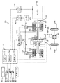
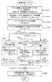
図1は、本発明の実施例としての動力出力装置を搭載するハイブリッド自動車20の構成の概略を示す構成図である。実施例のハイブリッド自動車20は、図示するように、エンジン22と、エンジン22のクランクシャフト26にダンパ28を介して接続されると共に駆動輪69a、69bにデファレンシャルギヤ68やギヤ機構66,駆動軸65を介して接続された動力分配統合機構30と、この動力分配統合機構30に接続された発電可能なモータMG1と、同じく動力分配統合機構30に接続された発電可能なモータMG2と、動力出力装置全体をコントロールするハイブリッド用電子制御ユニット70とを備える。
FIG. 1 is a configuration diagram showing an outline of the configuration of a
エンジン22は、ガソリンまたは軽油などの炭化水素系の燃料により動力を出力する内燃機関であり、エンジン22の運転状態を検出する各種センサから信号を入力するエンジン用電子制御ユニット(以下、エンジンECUという)24により燃料噴射制御や点火制御、吸入空気量調節制御などの運転制御を受けている。エンジンECU24は、ハイブリッド用電子制御ユニット70と通信しており、ハイブリッド用電子制御ユニット70からの制御信号によりエンジン22を運転制御すると共に必要に応じてエンジン22の運転状態に関するデータをハイブリッド用電子制御ユニット70に出力する。
The
動力分配統合機構30は、プラネタリギヤPと2つのクラッチC1,C2とにより構成されている。プラネタリギヤPのサンギヤ31にはモータMG1の回転軸が、リングギヤ32にはエンジン22のクランクシャフト26が、ピニオンギヤ33を連結するキャリア34には駆動軸65が、それぞれ接続されている。また、プラネタリギヤPのキャリア34はクラッチC1を介して、リングギヤ32はクラッチC2を介してそれぞれMG2に接続されている。駆動軸65はギヤ機構66およびデファレンシャルギヤ68を介して駆動輪69a,69bに機械的に連結されているから、駆動軸65に出力された動力は最終的には駆動輪69a、69bに出力されることになる。
The power distribution and
この動力分配統合機構30は、モータMG1の回転を停止させた状態のときにエンジン22からの動力をトルクを増幅して駆動軸65から出力することができるようエンジン22のクランクシャフト26とモータMG1の回転軸と駆動軸65とを連結すると共にクラッチC1,C2のオン,オフ操作によりモータMG2の回転軸を駆動軸65に連結したりエンジン22のクランクシャフト26に連結するものとなる。以下にクラッチC1,C2の各状態における動力分配統合機構30の動作について説明する。
The power distribution /
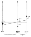
クラッチC1をオンとすると共にクラッチC2をオフとしたとき、即ち、モータMG2の回転軸を駆動軸65に連結したときの動力分配統合機構30の各回転要素における回転数とトルクとの力学的な関係を示す共線図の一例を図2に示す。図中、左端のS軸はモータMG1の回転数Nm1であるプラネタリギヤPのサンギヤ31の回転数を示し、C軸は駆動軸65の回転数NdおよびモータMG2の回転数Nm2であるプラネタリギヤPのキャリア34の回転数を示し、R軸はエンジン22のクランクシャフト26の回転数NeであるプラネタリギヤPのリングギヤ32の回転数を示す。これらの共線図は、各要素(各軸)に作用するトルクを共線を梁に見立てたときにこの梁に作用する力と同一視することができるものである。したがって、各軸に作用するトルク或いは作用させるべきトルクを、同様の力が作用している梁の釣り合いを解くことにより計算することができる。なお、図中、ρはプラネタリギヤPのギヤ比(サンギヤ31の歯数/リングギヤ32の歯数)である。この接続状態では、動力分配統合機構30は、モータMG1の回転を停止させた状態のときにエンジン22からの動力をトルクを増幅して駆動軸65から出力することができる連結状態における動力の駆動軸65への出力、即ち、エンジン22からのトルクとエンジン22の運転ポイント(回転数とトルク)を調整するモータMG1からのトルクとの和のトルクの駆動軸65への出力に加えて、モータMG2からのトルクの駆動軸65への出力を行なうことができる。このように、この接続状態は、モータMG2から駆動軸65に直接動力を出力することができることやモータMG1を回転停止に近い状態にすることによりエンジン22からの動力をトルクを増幅して駆動軸65に出力することができることから、駆動軸65に低回転高トルクの動力を出力するときに有利なものとなる。
When the clutch C1 is turned on and the clutch C2 is turned off, that is, when the rotational shaft of the motor MG2 is connected to the drive shaft 65, the dynamics of the rotational speed and torque in each rotational element of the power distribution and
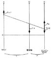
クラッチC1をオフとすると共にクラッチC2をオンとしたとき、即ち、モータMG2の回転軸をエンジン22のクランクシャフト26に連結したときの動力分配統合機構30の各回転要素における回転数とトルクとの力学的な関係を示す共線図の一例を図3に示す。この接続状態では、動力分配統合機構30は、エンジン22とモータMG2とからのトルクとエンジン22の運転ポイント(回転数とトルク)を調整するモータMG1からのトルクとの和のトルクを駆動軸65に出力する。この接続状態は、モータMG2の回転軸がエンジン22のクランクシャフト26に接続されているから、モータMG1の回転数Nm1が正の値で回転しているときには動力−電力−動力といったエネルギの循環(動力循環)を生じることはない。したがって、エンジン22の回転数Neが駆動軸65の回転数Nrより小さいとき、即ち駆動軸65に高回転低トルクの動力を出力するときには、モータMG1は正の値で回転するから、動力循環を生じることなくエンジン22から出力された動力をトルク変換して駆動軸65に出力することができる。したがって、この接続状態は駆動軸65に高回転低トルクの動力を出力するときに有利なものとなる。
When the clutch C1 is turned off and the clutch C2 is turned on, that is, when the rotational shaft of the motor MG2 is connected to the
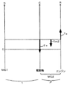
クラッチC1とクラッチC2とを共にオンとしたとき、即ち、エンジン22のクランクシャフト26と駆動軸65とモータMG1,MG2の回転軸とを一体の回転体としたときの動力分配統合機構30の各回転要素における回転数とトルクとの力学的な関係を示す共線図の一例を図4に示す。この接続状態では、エンジン22のクランクシャフト26と駆動軸65とが一体の回転体として回転するから、エンジン22を効率よく運転できる運転ポイントの動力を駆動軸65に出力するときには、効率よく動力を駆動軸65に出力することができる。したがって、この接続状態は、エンジン22を効率よく運転できる運転ポイントの動力を駆動軸65に出力することができるときに有利なものとなる。
Each of the power distribution and
モータMG1およびモータMG2は、いずれも発電機として駆動することができると共に電動機として駆動できる周知の同期発電電動機として構成されており、インバータ51,52を介してバッテリ60と電力のやりとりを行なう。インバータ51,52とバッテリ60とを接続する電力ライン64は、各インバータ51,52が共用する正極母線および負極母線として構成されており、モータMG1,MG2のいずれかで発電される電力を他のモータで消費することができるようになっている。したがって、バッテリ60は、モータMG1,MG2のいずれかから生じた電力や不足する電力により充放電されることになる。なお、モータMG1,MG2により電力収支のバランスをとるものとすれば、バッテリ60は充放電されない。モータMG1,MG2は、いずれもモータ用電子制御ユニット(以下、モータECUという)50により駆動制御されている。モータECU50には、モータMG1,MG2を駆動制御するために必要な信号、例えばモータMG1,MG2の回転子の回転位置を検出する回転位置検出センサ53,54からの信号や図示しない電流センサにより検出されるモータMG1,MG2に印加される相電流などが入力されており、モータECU50からは、インバータ51,52へのスイッチング制御信号が出力されている。モータECU50は、ハイブリッド用電子制御ユニット70と通信しており、ハイブリッド用電子制御ユニット70からの制御信号によってモータMG1,MG2を駆動制御すると共に必要に応じてモータMG1,MG2の運転状態に関するデータをハイブリッド用電子制御ユニット70に出力する。
Both motor MG1 and motor MG2 are configured as well-known synchronous generator motors that can be driven as generators and can be driven as motors, and exchange power with
バッテリ60は、バッテリ用電子制御ユニット(以下、バッテリECUという)62によって管理されている。バッテリECU62には、バッテリ60を管理するのに必要な信号、例えば,バッテリ60の端子間に設置された図示しない電圧センサからの端子間電圧,バッテリ60の出力端子に接続された電力ライン64に取り付けられた図示しない電流センサからの充放電電流,バッテリ60に取り付けられた図示しない温度センサからの電池温度などが入力されており、必要に応じてバッテリ60の状態に関するデータを通信によりハイブリッド用電子制御ユニット70に出力する。なお、バッテリECU62では、バッテリ60を管理するために電流センサにより検出された充放電電流の積算値に基づく残容量(SOC)やこの残容量(SOC)と電池温度とに基づく入出力制限Win,Woutなども演算または設定している。
The
ハイブリッド用電子制御ユニット70は、CPU72を中心とするマイクロプロセッサとして構成されており、CPU72の他に処理プログラムを記憶するROM74と、データを一時的に記憶するRAM76と、図示しない入出力ポートおよび通信ポートとを備える。ハイブリッド用電子制御ユニット70には、イグニッションスイッチ80からのイグニッション信号,シフトレバー81の操作位置を検出するシフトポジションセンサ82からのシフトポジションSP,アクセルペダル83の踏み込み量を検出するアクセルペダルポジションセンサ84からのアクセル開度Acc,ブレーキペダル85の踏み込み量を検出するブレーキペダルポジションセンサ86からのブレーキペダルポジションBP,車速センサ88からの車速Vなどが入力ポートを介して入力されている。ハイブリッド用電子制御ユニット70は、前述したように、エンジンECU24やモータECU50,バッテリECU62と通信ポートを介して接続されており、エンジンECU24やモータECU50,バッテリECU62と各種制御信号やデータのやりとりを行なっている。
The hybrid
こうして構成された実施例のハイブリッド自動車20は、運転者によるアクセルペダル83の踏み込み量に対応するアクセル開度Accと車速Vとに基づいて駆動軸65に出力すべき駆動要求トルクT*を計算し、この駆動要求トルクT*に対応する要求動力が駆動軸65に出力されるように、エンジン22とモータMG1とモータMG2とが運転制御される。エンジン22とモータMG1とモータMG2の運転制御としては、要求動力に見合う動力がエンジン22から出力されるようにエンジン22を運転制御すると共にエンジン22から出力される動力のすべてが動力分配統合機構30とモータMG1とモータMG2とによってトルク変換されて駆動軸65に出力されるようモータMG1およびモータMG2を駆動制御するトルク変換運転モードや要求動力とバッテリ60の充放電に必要な電力との和に見合う動力がエンジン22から出力されるようにエンジン22を運転制御すると共にバッテリ60の充放電を伴ってエンジン22から出力される動力の全部またはその一部が動力分配統合機構30とモータMG1とモータMG2とによるトルク変換を伴って要求動力が駆動軸65に出力されるようモータMG1およびモータMG2を駆動制御する充放電運転モード、エンジン22の運転を停止してモータMG1やモータMG2から要求動力に見合う動力を駆動軸65に出力するよう運転制御するモータ運転モードなどがある。なお、トルク変換運転モードと充放電運転モードはバッテリ60の充放電を行なうか否かの差があるだけで実質的な制御における差違はない。
The
次に、こうして構成された実施例のハイブリッド自動車20の動作、特にクラッチC1やクラッチC2の切り替えを含む基本的な動作について説明する。図5は、ハイブリッド用電子制御ユニット70により実行される駆動制御ルーチンの一例を示すフローチャートである。このルーチンは、所定時間毎(例えば8msec毎)に繰り返し実行される。
Next, the operation of the
駆動制御ルーチンが実行されると、ハイブリッド用電子制御ユニット70のCPU72は、まず、アクセルペダルポジションセンサ84からのアクセル開度Accや車速センサ88からの車速V,エンジン22の回転数Ne,モータMG1,MG2の回転数Nm1,Nm2,バッテリ60を充放電するための要求充放電パワーPb*など制御に必要なデータを入力する処理を実行する(ステップS100)。ここで、エンジン22の回転数Neは、図示しないクランクポジションセンサにより検出されたクランクシャフト26の回転位置に基づいて計算されたものをエンジンECU24から通信により入力するものとした。また、モータMG1,MG2の回転数Nm1,Nm2は、回転位置検出センサ53,54により検出されるモータMG1,MG2の回転子の回転位置に基づいて計算されたものをモータECU50から通信により入力するものとした。また、バッテリ60を充放電するための要求充放電パワーPb*は、残容量(SOC)に基づいて設定されたものをバッテリECU62から通信により入力するものとした。
When the drive control routine is executed, first, the
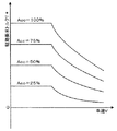
こうしてデータを入力すると、入力したアクセル開度Accと車速Vとに基づいて車両に要求されるトルクとして駆動軸65に出力すべき駆動要求トルクT*と車両に要求される車両要求パワーP*とを設定する(ステップS110)。駆動要求トルクT*は、実施例では、アクセル開度Accと車速Vと駆動要求トルクT*との関係を予め定めて要求トルク設定用マップとしてROM74に記憶しておき、アクセル開度Accと車速Vとが与えられると記憶したマップから対応する要求トルクT*を導出して設定するものとした。図6に要求トルク設定用マップの一例を示す。車両要求パワーP*は、設定した駆動要求トルクT*に駆動軸65の回転数Ndを乗じたものとバッテリ60が要求する要求充放電パワーPb*とロスLossとの和として計算することができる。なお、駆動軸65の回転数Ndは、車速Vに換算係数kを乗じることによって求めることができる。
When the data is input in this way, the required drive torque T * to be output to the drive shaft 65 as the torque required for the vehicle based on the input accelerator opening Acc and the vehicle speed V, and the required vehicle power P * required for the vehicle, Is set (step S110). In the embodiment, the drive request torque T * is determined in advance by storing the relationship between the accelerator opening Acc, the vehicle speed V, and the drive request torque T * in the
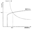
こうして駆動要求トルクT*と車両要求パワーP*とを設定すると、設定した車両要求パワーP*に基づいてエンジン22から出力すべきエンジン要求パワーPe*を設定する(ステップS120)。エンジン要求パワーPe*の設定は、エンジン22の応答性がモータMG1,MG2などに比して遅いことから、いままでにこのルーチンが実行されて設定されたエンジン要求パワーPe*と今回設定された車両要求パワーP*とを用いて車両要求パワーP*がいずれエンジン要求パワーPe*として設定されるようなまし処理やレート処理を用いてエンジン要求パワーPe*を設定する。続いて、設定したエンジン要求パワーPe*に基づいてエンジン22の目標回転数Ne*と目標トルクTe*とを設定する(ステップS130)。この設定は、エンジン22を効率よく動作させる動作ラインとエンジン要求パワーPe*とに基づいて目標回転数Ne*と目標トルクTe*とを設定する。エンジン22の動作ラインの一例と目標回転数Ne*と目標トルクTe*とを設定する様子を図7に示す。図示するように、目標回転数Ne*と目標トルクTe*は、動作ラインとエンジン要求パワーPe*(Ne*×Te*)が一定の曲線との交点により求めることができる。
When the drive request torque T * and the vehicle request power P * are thus set, the engine request power Pe * to be output from the
次に、車速Vを閾値Vref1や閾値Vref2と比較する(ステップS140)。ここで、閾値Vref1や閾値Vref2は、車両全体の効率をよくするクラッチC1,C2の接続状態を決定するために用いるものであり、閾値Vref1は比較的低速(例えば30km/hや40km/hなど)に設定されており、閾値Vref2は比較的高速(例えば、80km/hや90km/hなど)に設定されている。車速Vが閾値Vref1以下のときには、クラッチC1をオンすると共にクラッチC2をオフとしてモータMG2を駆動軸65に連結し(ステップS150)、動力分配統合機構30を低速で有利な図2の共線図に示す接続状態とする。そして、エンジン22が目標回転数Ne*で回転するようモータMG1のトルク指令Tm1*を次式(1)により計算して設定すると共に(ステップS160)、駆動要求トルクT*が駆動軸65に出力されるようモータMG2のトルク指令Tm2*を式(2)により計算して設定する(ステップS170)。ここで、式(1)は、エンジン22を目標回転数Ne*で回転させるようモータMG1のトルク指令Tm1*を計算するためのフィードバック制御における関係式であり、式(1)中、右辺第2項の「k1」は比例項のゲインであり、右辺第3項の「k2」は積分項のゲインである。また、式(2)は、上述した図2の共線図における力学的関係から、容易に求めることができる。
Next, the vehicle speed V is compared with the threshold value Vref1 and the threshold value Vref2 (step S140). Here, the threshold value Vref1 and the threshold value Vref2 are used to determine the connection state of the clutches C1 and C2 that improve the efficiency of the entire vehicle, and the threshold value Vref1 is a relatively low speed (for example, 30 km / h, 40 km / h, etc.). ) And the threshold value Vref2 is set to a relatively high speed (for example, 80 km / h, 90 km / h, etc.). When the vehicle speed V is less than or equal to the threshold value Vref1, the clutch C1 is turned on and the clutch C2 is turned off to connect the motor MG2 to the drive shaft 65 (step S150). Connection state shown in The torque command Tm1 * of the motor MG1 is calculated and set by the following equation (1) so that the
Tm1*=前回Tm1*+k1(Ne*−Ne)+k2∫(Ne*−Ne)dt (1)
Tm2*=T*−(1+1/ρ)Tm1* (2)
Tm1 * = previous Tm1 * + k1 (Ne * −Ne) + k2∫ (Ne * −Ne) dt (1)
Tm2 * = T * − (1 + 1 / ρ) Tm1 * (2)
こうしてモータMG1,MG2のトルク指令Tm1*,Tm2*を設定すると、設定したエンジン22の目標回転数Ne*と目標トルクTe*についてはエンジンECU24に送信すると共にモータMG1,MG2のトルク指令Tm1*,Tm2*についてはモータECU40に送信して(ステップS240)、駆動制御ルーチンを終了する。目標回転数Ne*と目標トルクTe*とを受信したエンジンECU24は、エンジン22が目標回転数Ne*と目標トルクTe*とによって示される運転ポイントで運転されるようにエンジン22における燃料噴射制御や点火制御などの制御を行なう。また、トルク指令Tm1*,Tm2*を受信したモータECU50は、トルク指令Tm1*でモータMG1が駆動されると共にトルク指令Tm2*でモータMG2が駆動されるようインバータ51,52のスイッチング素子のスイッチング制御を行なう。こうした制御により、比較的低速におけるエネルギ効率を向上させることができる。
When the torque commands Tm1 * and Tm2 * of the motors MG1 and MG2 are set in this way, the set target rotational speed Ne * and target torque Te * of the
ステップS140で車速Vが閾値Vref1以上かつVref2未満の比較的中速であると判断されると、クラッチC1,C2を共にオンして駆動軸65とエンジン22のクランクシャフト26とを連結し(ステップS180)、動力分配統合機構30を図4の共線図に示す接続状態とする。そして、エンジン22の目標回転数Ne*に駆動軸65の回転数Nd(k・V)を設定すると共にエンジン要求パワーPe*を設定した目標回転数Ne*で割って目標トルクTe*を設定し(ステップS190)、駆動軸65に駆動要求トルクT*が出力されるようモータMG1,MG2のトルク指令Tm1*,Tm2*を設定して(ステップS200)、設定したエンジン22の目標回転数Ne*と目標トルクTe*についてはエンジンECU24に送信すると共にモータMG1,MG2のトルク指令Tm1*,Tm2*についてはモータECU40に送信して(ステップS240)、駆動制御ルーチンを終了する。ここで、モータMG1,MG2のトルク指令Tm1*,Tm2*は、目標トルクTe*とを含めた和が駆動要求トルクT*となれば如何なる配分に設定してもよいが、このときに出力すべきトルクを効率よく出力できる側のモータからトルクを出力するよう制御する。こうした制御により、エンジン22からの動力を直接駆動軸65に出力することができるので、比較的中速時における車両のエネルギ効率を向上させることができる。
If it is determined in step S140 that the vehicle speed V is a relatively medium speed not less than the threshold value Vref1 and less than Vref2, the clutches C1 and C2 are both turned on to connect the drive shaft 65 and the
ステップS140で車速Vが閾値Vref2以上であると判定されると、クラッチC1をオフすると共にクラッチC2をオンしてモータMG2をエンジン22のクランクシャフト26に連結し(ステップS210)、動力分配統合機構30を高速で有利な図3の共線図に示す接続状態とする。エンジン22が目標回転数Ne*で回転するようモータMG2のトルク指令Tm2*を次式(3)により計算して設定すると共に(ステップS220)、駆動要求トルクT*が駆動軸65に出力されるようモータMG1のトルク指令Tm1*を式(4)により計算して設定する(ステップS230)。設定したエンジン22の目標回転数Ne*と目標トルクTe*についてはエンジンECU24に送信すると共にモータMG1,MG2のトルク指令Tm1*,Tm2*についてはモータECU40に送信して(ステップS240)、駆動制御ルーチンを終了する。こうした制御により、動力循環は生じることがないから、車両のエネルギ効率を向上させることができる。なお、式(3)は、上式(1)のTm1*をTm2*に、ゲイン「k1」,「k2」をゲイン「k3」,「k4」に各々置き換えたものであり、式(4)は式(2)と同様、図3の共線図における力学的関係から、容易に求めることができる。
If it is determined in step S140 that the vehicle speed V is greater than or equal to the threshold value Vref2, the clutch C1 is turned off and the clutch C2 is turned on to connect the motor MG2 to the
Tm2*=前回Tm2*+k3(Ne*−Ne)+k4∫(Ne*−Ne)dt (3)
Tm1*=ρ・T*/(1+ρ) (4)
Tm2 * = previous Tm2 * + k3 (Ne * −Ne) + k4∫ (Ne * −Ne) dt (3)
Tm1 * = ρ ・ T * / (1 + ρ) (4)
以上説明した実施例のハイブリッド自動車20によれば、走行状態に応じた接続状態に動力分配統合機構30を切り替えて走行することができる。この結果、車両全体のエネルギ効率を向上させることができる。即ち、車速Vが閾値Vref1以下では動力分配統合機構30を低速で有利な構成とするから、低速域におけるエネルギ効率を向上させることができる。車速Vが閾値Vref1以上かつVref2未満では駆動軸65とエンジン22のクランクシャフト26を直結して一体回転させ効率よく運転されたエンジン22からの動力を直接駆動軸65に出力するので中速域におけるエネルギ効率を向上させることができ、車速VがVref2以上では動力分配統合機構30を高速で有利な構成とするから、高速域におけるエネルギ効率を向上させることができる。
According to the
以上説明した実施例のハイブリッド自動車20では、車速Vが閾値Vref1以上かつ閾値Vref2未満であるときには、クラッチC1,C2を共にオンして駆動軸65およびエンジン22のクランクシャフト26を直結して一体回転するものとしたが、このような動作を行なわずクラッチC1,C2のうちのいずれか一方をオンとし他方をオフとする動作のみ行なうものとしてもよい。
In the
また、実施例のハイブリッド自動車20では、3軸式動力入出力手段としてプラネタリギヤPを用いるものとしたが、他の3軸式のギヤ機構を用いるものとしてもよい。
In the
さらに、実施例のハイブリッド自動車20では、運転者のアクセルペダル83の操作に基づいて要求動力を設定し、エンジン22とモータMG1とモータMG2とを制御するものとしたが、運転者のような操作者が存在せず、自動で出力すべき動力を設定するもの、例えば自動運転する列車や船舶などのようなものとしてもよい。
Furthermore, in the
実施例のハイブリッド自動車20では、車速に基づいてクラッチC1,C2を切り替えるものとしたが、他のもの、例えば、エネルギ効率や要求トルクに基づいてクラッチC1,C2を切り替えるものとしてもよい。また、車速Vを閾値Vref1および閾値Vref2と比較し、車速を3段階に区分して動力分配統合機構30の接続状態を切り替えるものとしたが、車速Vを4段階以上に区分して動力分配統合機構30の接続状態を切り替えるものとしてもよい。
In the
また、実施例のハイブリッド自動車20では、エンジン22を効率のよい運転ポイントで運転するものとしたが、これ以外の運転ポイントで運転するものとしてもよい。また、エンジン要求パワーPe*を設定する際なまし処理やレート処理を用いるものとしたが、これらのものを用いずにエンジン要求パワーPe*を設定するものとしてもよい。
In the
また、上述した実施例のハイブリッド自動車20では、動力分配統合機構30の構成として、プラネタリギヤPのサンギヤ31にモータMG1の回転軸を、リングギヤ32に内燃機関22のクランクシャフト26を、キャリア34に駆動軸65を各々接続し、モータMG2をクランクシャフト26または駆動軸65に接続するクラッチC1,C2を備えるものとしたが、一方の電動機が回転停止した状態のときに内燃機関から出力された動力をトルクを増幅して前記駆動軸に出力することができるよう内燃機関の出力軸と駆動軸と一方の電動機の回転軸とを連結すると共に他方の電動機の回転軸を内燃機関の出力軸と駆動軸とに切替可能なものであればいかなる構成としても構わない。
In the
上述した実施例では、ハイブリッド自動車20として説明したが、駆動軸65までの動力出力装置として適用してもよいし、エンジン22やモータMG1やモータMG2からの動力を駆動軸に伝達する動力伝達装置として適用してもよい。この場合、動力出力装置や動力伝達装置は、自動車以外の列車などの車両に搭載されるものとしてもよいし、船舶や航空機に搭載されるものとしてもよい。また、建設機械などに組み込まれるものとしても構わない。
In the above-described embodiment, the
以上、本発明を実施するための最良の形態について実施例を用いて説明したが、本発明はこうした実施例に何等限定されるものではなく、本発明の要旨を逸脱しない範囲内において、種々なる形態で実施し得ることは勿論である。 The best mode for carrying out the present invention has been described with reference to the embodiments. However, the present invention is not limited to these embodiments, and various modifications can be made without departing from the gist of the present invention. Of course, it can be implemented in the form.
20 ハイブリッド自動車、22 エンジン、24 エンジン用電子制御ユニット(エンジンECU)、26 クランクシャフト、28 ダンパ、30 動力分配統合機構、31 サンギヤ、32 リングギヤ、33 ピニオンギヤ、34 キャリア、50 モータ用電子制御ユニット(モータECU)、51,52 インバータ、53,54 回転位置検出センサ、60 バッテリ、62 バッテリ用電子制御ユニット(バッテリECU)、64 電力ライン、65 駆動軸、68 デファレンシャルギヤ、69a,69b 駆動輪、70 ハイブリッド用電子制御ユニット、72 CPU、74 ROM、76 RAM、80 イグニッションスイッチ、81 シフトレバー、82 シフトポジションセンサ、83 アクセルペダル、84 アクセルペダルポジションセンサ、85 ブレーキペダル、86 ブレーキペダルポジションセンサ、88 車速センサ、P プラネタリギヤ、MG1,MG2 モータ、C1,C2 クラッチ。 20 hybrid vehicle, 22 engine, 24 electronic control unit for engine (engine ECU), 26 crankshaft, 28 damper, 30 power distribution and integration mechanism, 31 sun gear, 32 ring gear, 33 pinion gear, 34 carrier, 50 electronic control unit for motor ( Motor ECU), 51, 52 inverter, 53, 54 rotational position detection sensor, 60 battery, 62 battery electronic control unit (battery ECU), 64 power line, 65 drive shaft, 68 differential gear, 69a, 69b drive wheel, 70 Electronic control unit for hybrid, 72 CPU, 74 ROM, 76 RAM, 80 ignition switch, 81 shift lever, 82 shift position sensor, 83 accelerator pedal, 84 accelerator pedal Jishon sensor, 85 brake pedal, 86 a brake pedal position sensor, 88 vehicle speed sensor, P planetary gear, MG1, MG2 motor, C1, C2 clutch.
Claims (10)
内燃機関と、
発電可能な第1の電動機と、
発電可能な第2の電動機と、
前記第1の電動機が回転停止した状態のときに前記内燃機関から出力された動力をトルクを増幅して前記駆動軸に出力することができるよう前記内燃機関の出力軸と前記駆動軸と前記第1の電動機の回転軸とを連結すると共に前記第2の電動機の回転軸を前記内燃機関の出力軸と前記駆動軸とに切替可能に連結する連結手段と、
を備える動力出力装置。 A power output device that outputs power to a drive shaft,
An internal combustion engine;
A first electric motor capable of generating electricity;
A second electric motor capable of generating electricity;
The output shaft of the internal combustion engine, the drive shaft, and the first shaft are capable of amplifying torque and outputting the power output from the internal combustion engine to the drive shaft when the first electric motor is stopped. Connecting means for connecting the rotating shaft of the first electric motor and the rotating shaft of the second electric motor to the output shaft of the internal combustion engine and the drive shaft in a switchable manner;
A power output device comprising:
操作者の操作に基づいて前記駆動軸に出力すべき要求動力を設定する要求動力設定手段と、
該設定された要求動力に基づく動力が前記駆動軸に出力されるよう前記内燃機関と前記第1の電動機と前記第2の電動機と前記連結手段とを制御する制御手段と、
を備える動力出力装置。 The power output device according to any one of claims 1 to 4,
Requested power setting means for setting required power to be output to the drive shaft based on an operation of an operator;
Control means for controlling the internal combustion engine, the first electric motor, the second electric motor, and the connecting means so that power based on the set required power is output to the drive shaft;
A power output device comprising:
共線図において順に並ぶ第1回転要素と第2回転要素と第3回転要素とを有し該第1回転要素が前記第1の電動機の回転軸に接続され該第2回転要素が前記駆動軸に接続され該第3回転要素が前記内燃機関の出力軸に接続された遊星歯車と、
前記第2の電動機の回転軸と前記第2回転要素との接続および接続の解除を行なう第1接続解除手段と、
前記第2の電動機の回転軸と前記第3回転要素との接続および接続の解除を行なう第2接続解除手段と、
を備える動力伝達装置。 Connected to the output shaft of the internal combustion engine, the rotary shaft of the first electric motor capable of generating power, and the rotary shaft of the second electric motor capable of generating power, and output from the internal combustion engine, the first electric motor and the second electric motor A power transmission device for torque-converting the transmitted power and transmitting it to the drive shaft,
A first rotation element, a second rotation element, and a third rotation element that are arranged in order in the alignment chart, the first rotation element being connected to the rotation shaft of the first motor, and the second rotation element being the drive shaft A planetary gear connected to the output shaft of the internal combustion engine,
First connection release means for connecting and releasing the connection between the rotating shaft of the second electric motor and the second rotating element;
Second connection release means for connecting and releasing the connection between the rotary shaft of the second electric motor and the third rotating element;
A power transmission device comprising:
Priority Applications (1)
| Application Number | Priority Date | Filing Date | Title |
|---|---|---|---|
| JP2004111400A JP4031769B2 (en) | 2004-04-05 | 2004-04-05 | Power output device, automobile equipped with the same, and power transmission device |
Applications Claiming Priority (1)
| Application Number | Priority Date | Filing Date | Title |
|---|---|---|---|
| JP2004111400A JP4031769B2 (en) | 2004-04-05 | 2004-04-05 | Power output device, automobile equipped with the same, and power transmission device |
Publications (2)
| Publication Number | Publication Date |
|---|---|
| JP2005291477A true JP2005291477A (en) | 2005-10-20 |
| JP4031769B2 JP4031769B2 (en) | 2008-01-09 |
Family
ID=35324619
Family Applications (1)
| Application Number | Title | Priority Date | Filing Date |
|---|---|---|---|
| JP2004111400A Expired - Fee Related JP4031769B2 (en) | 2004-04-05 | 2004-04-05 | Power output device, automobile equipped with the same, and power transmission device |
Country Status (1)
| Country | Link |
|---|---|
| JP (1) | JP4031769B2 (en) |
Cited By (3)
| Publication number | Priority date | Publication date | Assignee | Title |
|---|---|---|---|---|
| CN105751881A (en) * | 2016-02-26 | 2016-07-13 | 重庆大学 | Dual-motor planetary coupling drive system |
| CN106808988A (en) * | 2016-10-10 | 2017-06-09 | 蔚来汽车有限公司 | Electric automobile power coupling system, electric automobile with same and control method of electric automobile |
| WO2018068683A1 (en) * | 2016-10-10 | 2018-04-19 | 蔚来汽车有限公司 | Electric vehicle dynamic coupling system, electric vehicle having same, and control method therefor |
-
2004
- 2004-04-05 JP JP2004111400A patent/JP4031769B2/en not_active Expired - Fee Related
Cited By (5)
| Publication number | Priority date | Publication date | Assignee | Title |
|---|---|---|---|---|
| CN105751881A (en) * | 2016-02-26 | 2016-07-13 | 重庆大学 | Dual-motor planetary coupling drive system |
| CN105751881B (en) * | 2016-02-26 | 2018-07-06 | 重庆大学 | A kind of bi-motor planet coupling drive system |
| CN106808988A (en) * | 2016-10-10 | 2017-06-09 | 蔚来汽车有限公司 | Electric automobile power coupling system, electric automobile with same and control method of electric automobile |
| WO2018068683A1 (en) * | 2016-10-10 | 2018-04-19 | 蔚来汽车有限公司 | Electric vehicle dynamic coupling system, electric vehicle having same, and control method therefor |
| US10384536B2 (en) | 2016-10-10 | 2019-08-20 | Nio Nextev Limited | Power coupling system for electric vehicle, electric vehicle having the same and control method thereof |
Also Published As
| Publication number | Publication date |
|---|---|
| JP4031769B2 (en) | 2008-01-09 |
Similar Documents
| Publication | Publication Date | Title |
|---|---|---|
| JP4038183B2 (en) | Power output device, automobile equipped with the same, and power transmission device | |
| JP4086018B2 (en) | HYBRID VEHICLE, ITS CONTROL METHOD, AND POWER OUTPUT DEVICE | |
| JP3997955B2 (en) | Hybrid vehicle and control method thereof | |
| JP4135681B2 (en) | POWER OUTPUT DEVICE, HYBRID VEHICLE HAVING THE SAME AND CONTROL METHOD THEREOF | |
| CN100431886C (en) | Power take-off device, its control device, and control method for the power take-off device | |
| JP2008056236A (en) | Power output device and automobile equipped with the same | |
| JP2006094626A (en) | Hybrid vehicle and control method thereof | |
| JP2007091073A (en) | Drive device, automobile equipped with the same, and drive device control method | |
| JP4229105B2 (en) | Hybrid vehicle and control method thereof | |
| JP2009126253A (en) | Hybrid vehicle and control method thereof | |
| JP4031770B2 (en) | Power output device and automobile equipped with the same | |
| JP4466635B2 (en) | POWER OUTPUT DEVICE, ITS CONTROL METHOD, AND VEHICLE | |
| JP2007069625A (en) | Hybrid vehicle and control method thereof | |
| JP3812425B2 (en) | Power output apparatus and automobile equipped with the same | |
| JP4005589B2 (en) | Power output device, automobile equipped with the same, and power transmission device | |
| JP4031769B2 (en) | Power output device, automobile equipped with the same, and power transmission device | |
| JP2005081931A (en) | Power output device and automobile equipped with the same | |
| JP3846453B2 (en) | POWER OUTPUT DEVICE, ITS CONTROL METHOD, AND AUTOMOBILE MOUNTING THE SAME | |
| JP2005081929A (en) | Power output device and automobile equipped with the same | |
| JP3931854B2 (en) | POWER OUTPUT DEVICE, ITS CONTROL METHOD, AND AUTOMOBILE | |
| JP2007099165A (en) | POWER OUTPUT DEVICE, AUTOMOBILE MOUNTING THE SAME, DRIVE DEVICE, AND CONTROL METHOD FOR POWER OUTPUT DEVICE | |
| JP4345765B2 (en) | Vehicle and control method thereof | |
| JP4267410B2 (en) | Power output device and automobile equipped with the same | |
| JP2007112291A (en) | POWER OUTPUT DEVICE, VEHICLE MOUNTING THE SAME, AND METHOD FOR CONTROLLING POWER OUTPUT DEVICE | |
| JP2005297729A (en) | POWER OUTPUT DEVICE AND AUTOMOBILE MOUNTING THE SAME, DRIVE DEVICE AND POWER TRANSMISSION DEVICE |
Legal Events
| Date | Code | Title | Description |
|---|---|---|---|
| A711 | Notification of change in applicant |
Free format text: JAPANESE INTERMEDIATE CODE: A711 Effective date: 20051129 |
|
| A521 | Request for written amendment filed |
Free format text: JAPANESE INTERMEDIATE CODE: A821 Effective date: 20051130 |
|
| A621 | Written request for application examination |
Free format text: JAPANESE INTERMEDIATE CODE: A621 Effective date: 20070322 |
|
| A131 | Notification of reasons for refusal |
Free format text: JAPANESE INTERMEDIATE CODE: A131 Effective date: 20070807 |
|
| A521 | Request for written amendment filed |
Free format text: JAPANESE INTERMEDIATE CODE: A523 Effective date: 20070928 |
|
| TRDD | Decision of grant or rejection written | ||
| A01 | Written decision to grant a patent or to grant a registration (utility model) |
Free format text: JAPANESE INTERMEDIATE CODE: A01 Effective date: 20071016 |
|
| A61 | First payment of annual fees (during grant procedure) |
Free format text: JAPANESE INTERMEDIATE CODE: A61 Effective date: 20071019 |
|
| FPAY | Renewal fee payment (event date is renewal date of database) |
Free format text: PAYMENT UNTIL: 20101026 Year of fee payment: 3 |
|
| LAPS | Cancellation because of no payment of annual fees |