JP2005291476A - Hybrid vehicle mode transition control device - Google Patents
Hybrid vehicle mode transition control device Download PDFInfo
- Publication number
- JP2005291476A JP2005291476A JP2004111377A JP2004111377A JP2005291476A JP 2005291476 A JP2005291476 A JP 2005291476A JP 2004111377 A JP2004111377 A JP 2004111377A JP 2004111377 A JP2004111377 A JP 2004111377A JP 2005291476 A JP2005291476 A JP 2005291476A
- Authority
- JP
- Japan
- Prior art keywords
- mode
- continuously variable
- low
- vehicle
- variable transmission
- Prior art date
- Legal status (The legal status is an assumption and is not a legal conclusion. Google has not performed a legal analysis and makes no representation as to the accuracy of the status listed.)
- Granted
Links
Images


Classifications
-
- Y—GENERAL TAGGING OF NEW TECHNOLOGICAL DEVELOPMENTS; GENERAL TAGGING OF CROSS-SECTIONAL TECHNOLOGIES SPANNING OVER SEVERAL SECTIONS OF THE IPC; TECHNICAL SUBJECTS COVERED BY FORMER USPC CROSS-REFERENCE ART COLLECTIONS [XRACs] AND DIGESTS
- Y02—TECHNOLOGIES OR APPLICATIONS FOR MITIGATION OR ADAPTATION AGAINST CLIMATE CHANGE
- Y02T—CLIMATE CHANGE MITIGATION TECHNOLOGIES RELATED TO TRANSPORTATION
- Y02T10/00—Road transport of goods or passengers
- Y02T10/60—Other road transportation technologies with climate change mitigation effect
- Y02T10/62—Hybrid vehicles
Landscapes
- Hybrid Electric Vehicles (AREA)
- Control Of Transmission Device (AREA)
- Electric Propulsion And Braking For Vehicles (AREA)
Abstract
【課題】 無段変速モードを選択しての車両減速後に再加速を行う走行時、スムーズで良好な再加速性を得ることができるハイブリッド車のモード遷移制御装置を提供すること。
【解決手段】 共線図上に4つ以上の入出力要素が配列される差動装置を有し、前記入出力要素のうちの内側に配列される2つの要素の一方にエンジンEからの入力を、他方に駆動系統への出力軸OUTをそれぞれ割り当てると共に、前記内側の要素の両外側に配列される2つの要素にそれぞれ第1モータジェネレータMG1と第2モータジェネレータMG2とを連結した駆動力合成変速機TMを備えたハイブリッド車において、走行モードとして、少なくとも無段変速比により走行する「無段変速モード」と、前記差動装置の回転要素を変速機ケースに固定することでロー側の固定変速比により走行する「ローギヤ固定モード」と、を有し、前記「無段変速モード」を選択しての車両減速時、車速が設定車速以下になると、強制的に「無段変速モード」から「ローギヤ固定モード」へモード遷移する再加速対応モード遷移制御手段を設けた。
【選択図】 図6
PROBLEM TO BE SOLVED: To provide a mode transition control device for a hybrid vehicle capable of obtaining a smooth and good reacceleration property during traveling in which reacceleration is performed after vehicle deceleration by selecting a continuously variable transmission mode.
SOLUTION: A differential device in which four or more input / output elements are arranged on a nomographic chart, and an input from an engine E is input to one of two elements arranged inside the input / output elements. And the other is assigned the output shaft OUT to the drive system, and the driving force composition is made by connecting the first motor generator MG1 and the second motor generator MG2 to the two elements arranged on both outer sides of the inner element, respectively. In a hybrid vehicle equipped with the transmission TM, as a driving mode, a “continuously variable transmission mode” in which the vehicle is driven at least with a continuously variable transmission ratio, and the rotation element of the differential device is fixed to the transmission case to fix on the low side. When the vehicle speed is lower than the set vehicle speed when the vehicle is decelerated by selecting the “continuously variable transmission mode”, the vehicle is forced to start from It provided reacceleration response mode transition control means for mode transition to a low gear fixed mode ".
[Selection] Figure 6
Description
本発明は、車両の駆動系に適用され、走行モードとして、少なくとも無段変速モードとローギヤ固定モードを有するハイブリッド車のモード遷移制御装置に関する。 The present invention relates to a mode transition control device for a hybrid vehicle that is applied to a drive system of a vehicle and has at least a continuously variable transmission mode and a low gear fixed mode as travel modes.
従来、共線図上に4つの入出力要素が配列される4要素2自由度の遊星歯車機構を構成し、前記入出力要素のうちの内側に配列される2つの要素の一方にエンジンからの入力を、他方に駆動系統への出力をそれぞれ割り当てると共に、前記内側の要素の両外側に配列される2つの要素にそれぞれ第1モータジェネレータと第2モータジェネレータとを連結したハイブリッド駆動装置が知られていて、このハイブリッド駆動装置では、走行モードとして、エンジンと2つのモータジェネレータを用いて走行する「無段変速モード」と、ローブレーキを締結し、エンジンと2つのモータジェネレータ、あるいは、2つのモータジェネレータのみを用いて走行する「ローギヤ固定モード」と、を有する(例えば、特許文献1参照)。
しかしながら、上記従来のハイブリッド駆動装置にあっては、各走行モードを割り振り設定した走行モードマップを用いて走行モードの選択が行われ、選択される走行モードが選択されている現在の走行モードと異なる場合にのみモード遷移制御を行うものであるため、無段変速モードが選択されている減速時、停車前に再度アクセルペダルを踏み込んで再加速する場合、再加速後にモード遷移車速を超えて無段変速モードからローギヤ固定モードへのモード遷移が行われる。この結果、再加速時のモード遷移となり、モード遷移に伴う駆動力の変動により再加速がスムーズに行われないし、また、高い駆動力要求があった場合には、ローギヤ固定モードへのモード遷移が遅れることで、再加速性が劣るという問題がある。 However, in the above-described conventional hybrid drive device, the travel mode is selected using the travel mode map in which each travel mode is allocated and set, and the selected travel mode is different from the current travel mode selected. Therefore, when the vehicle is decelerated when the continuously variable transmission mode is selected, if the accelerator pedal is stepped on again before stopping to re-accelerate, the mode transition vehicle speed will be exceeded after re-acceleration. Mode transition from the shift mode to the low gear fixed mode is performed. As a result, mode transition occurs during re-acceleration, and re-acceleration is not performed smoothly due to fluctuations in driving force accompanying mode transition, and when there is a high driving force request, mode transition to the low gear fixed mode is performed. There is a problem that the reacceleration performance is inferior due to the delay.
本発明は、上記問題に着目してなされたもので、無段変速モードを選択しての車両減速後に再加速を行う走行時、スムーズで良好な再加速性を得ることができるハイブリッド車のモード遷移制御装置を提供することを目的とする。 The present invention has been made paying attention to the above-mentioned problem, and is a hybrid vehicle mode capable of obtaining a smooth and good reacceleration performance when traveling in which re-acceleration is performed after the vehicle is decelerated by selecting the continuously variable transmission mode. An object is to provide a transition control device.
上記目的を達成するため、本発明では、共線図上に4つ以上の入出力要素が配列される差動装置を有し、前記入出力要素のうちの内側に配列される2つの要素の一方にエンジンからの入力を、他方に駆動系統への出力部材をそれぞれ割り当てると共に、前記内側の要素の両外側に配列される2つの要素にそれぞれ第1モータジェネレータと第2モータジェネレータとを連結したハイブリッド車のモード遷移制御装置において、
走行モードとして、少なくとも無段変速比により走行する無段変速モードと、前記差動装置の回転要素を変速機ケースに固定することでロー側の固定変速比により走行するローギヤ固定モードと、を有し、
前記無段変速モードを選択しての車両減速時、車速が設定車速以下になると、強制的に無段変速モードからローギヤ固定モードへモード遷移する再加速対応モード遷移制御手段を設けた。
In order to achieve the above object, the present invention has a differential device in which four or more input / output elements are arranged on a collinear diagram, and two elements arranged inside the input / output elements. The input from the engine is assigned to one side, and the output member to the drive system is assigned to the other side, and the first motor generator and the second motor generator are connected to the two elements arranged on both outer sides of the inner elements, respectively. In a hybrid vehicle mode transition control device,
The travel mode includes a continuously variable transmission mode that travels at least at a continuously variable transmission ratio, and a low gear fixed mode that travels at a fixed transmission ratio on the low side by fixing the rotating element of the differential device to the transmission case. And
When the vehicle is decelerated while the continuously variable transmission mode is selected, there is provided a re-acceleration-compatible mode transition control means for forcibly shifting the mode from the continuously variable transmission mode to the low gear fixed mode when the vehicle speed becomes the set vehicle speed or less.
よって、本発明のハイブリッド車のモード遷移制御装置にあっては、再加速対応モード遷移制御手段において、無段変速モードを選択しての車両減速時、車速が設定車速以下になると、強制的に無段変速モードからローギヤ固定モードへのモード遷移が実行される。すなわち、車両減速時に無段変速モードからローギヤ固定モードへモード遷移が行われることになり、その後、ドライバが再加速を意図してアクセルペダルを踏み込む時点では、既にローギヤ固定モードへのモード遷移が終了し、再加速に備えている。この結果、モード遷移時に懸念される駆動力の抜けもしくは飛び出しが再加速時に発生しないため、無段変速モードを選択しての車両減速後に再加速を行う走行時、スムーズな再加速性が確保される。また、再加速に備えて駆動力が出せるローギヤ固定モードへのモード遷移を終えているため、アクセル踏み込み操作による高い駆動力要求に対してもアクセル操作に応答する良好な再加速性を得ることができる。 Therefore, in the hybrid vehicle mode transition control device of the present invention, when the vehicle speed is reduced below the set vehicle speed when the vehicle is decelerated while the continuously variable mode is selected in the re-acceleration compatible mode transition control means, A mode transition from the continuously variable transmission mode to the low gear fixed mode is executed. That is, when the vehicle decelerates, the mode transition from the continuously variable transmission mode to the low gear fixed mode is performed, and then the mode transition to the low gear fixed mode is already completed when the driver depresses the accelerator pedal with the intention of reacceleration. And be prepared for re-acceleration. As a result, there is no driving force dropout or jumping out at the time of mode transition during re-acceleration, so smooth re-acceleration is ensured when running re-acceleration after vehicle deceleration with the continuously variable mode selected. The In addition, because the mode transition to the low gear fixed mode where the driving force can be output in preparation for re-acceleration is completed, it is possible to obtain a good re-acceleration response to the accelerator operation even for a high driving force request due to the accelerator depressing operation. it can.
以下、本発明のハイブリッド車のモード遷移制御装置を実現する最良の形態を、図面に示す実施例1に基づいて説明する。 Hereinafter, the best mode for realizing a mode transition control device for a hybrid vehicle of the present invention will be described based on Example 1 shown in the drawings.
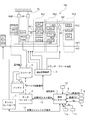
まず、ハイブリッド車の駆動系構成を説明する。
図1は実施例1のモード遷移制御装置が適用されたハイブリッド車の駆動系を示す全体システム図である。実施例1におけるハイブリッド車の駆動系は、図1に示すように、エンジンEと、第1モータジェネレータMG1と、第2モータジェネレータMG2と、出力軸OUT(出力部材)と、駆動力合成変速機TMと、を有する。
First, the drive system configuration of the hybrid vehicle will be described.
FIG. 1 is an overall system diagram showing a drive system of a hybrid vehicle to which the mode transition control device of
前記駆動力合成変速機TMは、第1遊星歯車PG1(差動装置)と、第2遊星歯車PG2(差動装置)と、第3遊星歯車PG3(差動装置)と、エンジンクラッチECと、ローブレーキLB(第1摩擦締結要素)と、ハイクラッチHC(第2摩擦締結要素)と、ハイローブレーキHLB(第3摩擦締結要素)と、を有する。 The driving force combined transmission TM includes a first planetary gear PG1 (differential device), a second planetary gear PG2 (differential device), a third planetary gear PG3 (differential device), an engine clutch EC, It has a low brake LB (first friction engagement element), a high clutch HC (second friction engagement element), and a high / low brake HLB (third friction engagement element).
前記エンジンEは、ガソリンエンジンやディーゼルエンジンであり、後述するエンジンコントローラ1からの制御指令に基づいて、スロットルバルブのバルブ開度などが制御yされる。
The engine E is a gasoline engine or a diesel engine, and the valve opening degree of the throttle valve is controlled based on a control command from the
前記第1モータジェネレータMG1と第2モータジェネレータMG2は、永久磁石を埋設したロータと、ステータコイルが巻き付けられたステータと、を有する同期型モータジェネレータであり、後述するモータコントローラ2からの制御指令に基づいて、インバータ3により作り出された三相交流をそれぞれのステータコイルに印加することにより独立に制御される。
The first motor generator MG1 and the second motor generator MG2 are synchronous motor generators having a rotor in which permanent magnets are embedded and a stator around which a stator coil is wound. Based on this, the three-phase alternating current generated by the
前記駆動力合成変速機TMの第1遊星歯車PG1と第2遊星歯車PG2と第3遊星歯車PG3とは、何れもシングルピニオン型遊星歯車である。前記第1遊星歯車PG1は、第1サンギヤS1と、第1ピニオンP1を支持する第1ピニオンキャリアPC1と、第1ピニオンP1に噛み合う第1リングギヤR1と、によって構成されている。前記第2遊星歯車PG2は、第2サンギヤS2と、第2ピニオンP2を支持する第2ピニオンキャリアPC2と、第2ピニオンP2に噛み合う第2リングギヤR2と、によって構成されている。前記第3遊星歯車PG3は、第3サンギヤS3と、第3ピニオンP3を支持する第3ピニオンキャリアPC3と、第3ピニオンP3に噛み合う第3リングギヤR3と、によって構成されている。 The first planetary gear PG1, the second planetary gear PG2, and the third planetary gear PG3 of the driving force combining transmission TM are all single pinion type planetary gears. The first planetary gear PG1 includes a first sun gear S1, a first pinion carrier PC1 that supports the first pinion P1, and a first ring gear R1 that meshes with the first pinion P1. The second planetary gear PG2 includes a second sun gear S2, a second pinion carrier PC2 that supports the second pinion P2, and a second ring gear R2 that meshes with the second pinion P2. The third planetary gear PG3 includes a third sun gear S3, a third pinion carrier PC3 that supports the third pinion P3, and a third ring gear R3 that meshes with the third pinion P3.
前記第1サンギヤS1と前記第2サンギヤS2とは第1回転メンバM1により直結され、前記第1リングギヤR1と第3サンギヤS3とは第2回転メンバM2により直結され、前記第2ピニオンキャリアPC2と前記第3リングギヤR3とは第3回転メンバM3により直結される。したがって、3組の遊星歯車PG1,PG2,PG3は、第1回転メンバM1と第2回転メンバM2と第3回転メンバM3と第1ピニオンキャリアPC1と第2リングギヤR2と第3ピニオンキャリアPC3との6つの回転要素を有する。 The first sun gear S1 and the second sun gear S2 are directly connected by a first rotating member M1, and the first ring gear R1 and the third sun gear S3 are directly connected by a second rotating member M2, and are connected to the second pinion carrier PC2. The third ring gear R3 is directly connected by a third rotating member M3. Accordingly, the three planetary gears PG1, PG2, and PG3 include the first rotating member M1, the second rotating member M2, the third rotating member M3, the first pinion carrier PC1, the second ring gear R2, and the third pinion carrier PC3. It has 6 rotating elements.
前記差動装置の6つの回転要素に対する動力源E,MG1,MG2と出力軸OUTと各係合要素EC,LB,HC,HLBの連結関係について説明する。
前記第1回転メンバM1(S1,S2)には、第2モータジェネレータMG2が連結されている。
前記第2回転メンバM2(R1,R3)には、入出力要素の何れにも連結されていない。
前記第3回転メンバM3(PC2,R3)には、エンジンクラッチECを介してエンジンEが連結されている。
前記第1ピニオンキャリアPC1には、ハイクラッチHCを介して第2モータジェネレータMG2が連結されている。また、ローブレーキLBを介して変速機ケースTCに連結されている。
前記第2リングギヤR2には、第1モータジェネレータMG1が連結されている。また、ハイローブレーキHLBを介して変速機ケースTCに連結されている。
前記第3ピニオンキャリアPC3には、出力軸OUTが連結されている。なお、出力軸OUTからは、図外のプロペラシャフトやディファレンシャルやドライブシャフトを介して左右の駆動輪に駆動力が伝達される。
A connection relationship between the power sources E, MG1, MG2, the output shaft OUT, and the engagement elements EC, LB, HC, HLB for the six rotating elements of the differential device will be described.
A second motor generator MG2 is connected to the first rotating member M1 (S1, S2).
The second rotating member M2 (R1, R3) is not connected to any input / output element.
An engine E is connected to the third rotating member M3 (PC2, R3) via an engine clutch EC.
A second motor generator MG2 is connected to the first pinion carrier PC1 via a high clutch HC. Further, it is connected to the transmission case TC via a low brake LB.
A first motor generator MG1 is connected to the second ring gear R2. Further, it is connected to the transmission case TC via a high / low brake HLB.
An output shaft OUT is connected to the third pinion carrier PC3. A driving force is transmitted from the output shaft OUT to the left and right driving wheels via a propeller shaft, a differential, and a drive shaft (not shown).
上記連結関係により、図2に示す共線図上において、第1モータジェネレータMG1(R2)、エンジンE(PC2,R3)、出力軸OUT(PC3)、第2モータジェネレータMG2(S1,S2)の順に配列され、遊星歯車列の動的な動作を簡易的に表せる剛体レバーモデル(第1遊星歯車PG1のレバー(1)、第2遊星歯車PG2のレバー(2)、第3遊星歯車PG3のレバー(3))を導入することができる。ここで、「共線図」とは、差動歯車のギヤ比を考える場合、式により求める方法に代え、より簡単で分かりやすい作図により求める方法で用いられる速度線図であり、縦軸に各回転要素の回転数(回転速度)をとり、横軸にリングギヤ、キャリア、サンギヤ等の各回転要素をとり、各回転要素の間隔をサンギヤとリングギヤの歯数比に基づく共線図レバー比(α、β、δ)になるように配置したものである。 Due to the above connection relationship, the first motor generator MG1 (R2), the engine E (PC2, R3), the output shaft OUT (PC3), and the second motor generator MG2 (S1, S2) on the alignment chart shown in FIG. A rigid lever model that is arranged in order and can easily express the dynamic operation of the planetary gear train (the first planetary gear PG1 lever (1), the second planetary gear PG2 lever (2), the third planetary gear PG3 lever) (3)) can be introduced. Here, the “collinear diagram” is a velocity diagram used in a simple and easy-to-understand method of drawing instead of the method of obtaining by equation when considering the gear ratio of the differential gear, Take the number of rotations (rotation speed) of the rotating elements, take each rotating element such as ring gear, carrier, sun gear, etc. on the horizontal axis, and set the interval between each rotating element to the collinear lever ratio (α , Β, δ).
前記エンジンクラッチECは、油圧により締結される多板摩擦クラッチであり、図2の共線図上において、エンジンEとの回転速度軸と一致する位置に配置され、締結によりエンジンEの回転とトルクを、エンジン入力回転要素である第3回転メンバM3(PC2,R3)に入力する。 The engine clutch EC is a multi-plate friction clutch that is engaged by hydraulic pressure, and is disposed at a position that coincides with the rotational speed axis of the engine E on the alignment chart of FIG. Is input to the third rotation member M3 (PC2, R3) which is an engine input rotation element.
前記ローブレーキLBは、油圧により締結される多板摩擦ブレーキであり、図2の共線図上において、第2モータジェネレータMG2の回転速度軸より外側位置に配置され、図2に示すように、締結によりロー側変速比を分担するローギヤ固定モードとロー側無段変速モードを実現する。 The low brake LB is a multi-plate friction brake fastened by hydraulic pressure, and is disposed on the outer side of the rotational speed axis of the second motor generator MG2 on the alignment chart of FIG. A low gear fixed mode and a low-side continuously variable transmission mode that share the low-side gear ratio are realized by fastening.
前記ハイクラッチHCは、油圧により締結される多板摩擦クラッチであり、図2の共線図上において、第2モータジェネレータMG2の回転速度軸と一致する位置に配置され、締結によりハイ側変速比を分担する2速固定変速モードとハイ側無段変速モードとハイギヤ固定モードを実現する。 The high clutch HC is a multi-plate friction clutch that is engaged by hydraulic pressure, and is disposed at a position that coincides with the rotational speed axis of the second motor generator MG2 on the alignment chart of FIG. 2 speed fixed transmission mode, high side continuously variable transmission mode, and high gear fixed mode are realized.
前記ハイローブレーキHLBは、油圧により締結される多板摩擦ブレーキであり、図2の共線図上において、第1モータジェネレータMG1の回転速度軸と一致する位置に配置され、ローブレーキLBと共に締結することにより変速比をアンダードライブ側のローギヤ固定モードとし、ハイクラッチHCと共に締結することにより変速比をオーバードライブ側のハイギヤ固定モードとする。 The high / low brake HLB is a multi-plate friction brake fastened by hydraulic pressure, and is arranged at a position coincident with the rotational speed axis of the first motor generator MG1 on the alignment chart of FIG. 2 and fastened together with the low brake LB. Thus, the gear ratio is set to the low gear fixing mode on the underdrive side, and the gear ratio is set to the high gear fixing mode on the overdrive side by engaging with the high clutch HC.
次に、ハイブリッド車の制御系を説明する。
実施例1におけるハイブリッド車の制御系は、図1に示すように、エンジンコントローラ1と、モータコントローラ2と、インバータ3と、バッテリ4と、油圧制御装置5と、統合コントローラ6と、アクセル開度センサ7と、車速センサ8と、エンジン回転数センサ9と、第1モータジェネレータ回転数センサ10と、第2モータジェネレータ回転数センサ11と、第3リングギヤ回転数センサ12と、を有して構成されている。
Next, the control system of the hybrid vehicle will be described.
As shown in FIG. 1, the control system of the hybrid vehicle in the first embodiment includes an
前記エンジンコントローラ1は、アクセル開度センサ7からのアクセル開度APとエンジン回転数センサ9からのエンジン回転数Neを入力する統合コントローラ6からの目標エンジントルク指令等に応じ、エンジン動作点(Ne,Te)を制御する指令を、例えば、図外のスロットルバルブアクチュエータへ出力する。
The
前記モータコントローラ2は、レゾルバによる両モータジェネレータ回転数センサ10、11からのモータジェネレータ回転数N1,N2を入力する統合コントローラ6からの目標モータジェネレータトルク指令等に応じ、第1モータジェネレータMG1のモータ動作点(N1,T1)と、第2モータジェネレータMG2のモータ動作点(N2,T2)と、をそれぞれ独立に制御する指令をインバータ3へ出力する。なお、このモータコントローラ2からは、バッテリ4の充電状態をあらわすバッテリS.O.Cの情報が統合コントローラ6に対して出力される。
The
前記インバータ3は、前記第1モータジェネレータMG1と第2モータジェネレータMG2との各ステータコイルに接続され、モータコントローラ2からの指令により独立した3相交流を作り出す。このインバータ3には、力行時に放電し回生時に充電するバッテリ4が接続されている。
The
前記油圧制御装置5は、統合コントローラ6からの油圧指令を受け、エンジンクラッチECと、ローブレーキLBと、ハイクラッチHCと、ハイローブレーキHLBと、の締結油圧制御及び解放油圧制御を行う。この締結油圧制御及び解放油圧制御には、滑り締結制御や滑り解放制御による半クラッチ制御も含む。
The
前記統合コントローラ6は、アクセル開度センサ7からのアクセル開度APと、車速センサ8からの車速VSPと、エンジン回転数センサ9からのエンジン回転数Neと、第1モータジェネレータ回転数センサ10からの第1モータジェネレータ回転数N1と、第2モータジェネレータ回転数センサ11からの第2モータジェネレータ回転数N2と、第3リングギヤ回転数センサ12からのエンジン入力回転速度ωin等の情報を入力し、所定の演算処理を行う。そして、エンジンコントローラ1、モータコントローラ2、油圧制御装置5に対し演算処理結果にしたがって制御指令を出力する。
The
なお、統合コントローラ6とエンジンコントローラ1、および、統合コントローラ6とモータコントローラ2とは、情報交換のためにそれぞれ双方向通信線14、15により接続されている。
The
次に、ハイブリッド車の走行モードについて説明する。 Next, the travel mode of the hybrid vehicle will be described.
走行モードとしては、ローギヤ固定モード(以下、「Lowモード」という。)と、ロー側無段変速モード(以下、「Low-iVTモード」という。)と、2速固定モード(以下、「2ndモード」という。)と、ハイ側無段変速モード(以下、「High-iVTモード」という。)と、ハイギヤ固定モード(以下、「Highモード」という。)と、の5つの走行モードを有する。 The driving mode includes a low gear fixed mode (hereinafter referred to as “Low mode”), a low-side continuously variable transmission mode (hereinafter referred to as “Low-iVT mode”), and a two-speed fixed mode (hereinafter referred to as “2nd mode”). ), A high-side continuously variable transmission mode (hereinafter referred to as “High-iVT mode”), and a high gear fixed mode (hereinafter referred to as “High mode”).
前記5つの走行モードについては、エンジンEを用いないで両モータージェネレータMG1,MG2のみで走行する電気自動車モード(以下、「EVモード」という。)と、エンジンEと両モータージェネレータMG1,MG2を用いて走行するハイブリッド車モード(以下、「HEVモード」という。)とに分けられる。 Regarding the five driving modes, an electric vehicle mode (hereinafter referred to as “EV mode”) in which only the motor generators MG1 and MG2 are driven without using the engine E, and an engine E and both motor generators MG1 and MG2 are used. And a hybrid vehicle mode (hereinafter referred to as “HEV mode”).
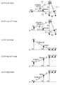
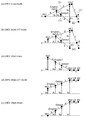
よって、図2及び図3に示すように、「EVモード」と「HEVモード」とを合わせると「10の走行モード」が実現されることになる。ここで、図2(a)にEVモード関連の「EV-Lowモード」の共線図、図2(b)に「EV-Low-iVTモード」の共線図、図2(c)に「EV-2ndモード」の共線図、図2(d)に「EV-High-iVTモード」の共線図、図2(e)に「EV-Highモード」の共線図をそれぞれ示す。また、図3(a)にHEVモード関連の「HEV-Lowモード」の共線図、図3(b)に「HEV-Low-iVTモード」の共線図、図3(c)に「HEV-2ndモード」の共線図、図3(d)に「HEV-High-iVTモード」の共線図、図3(e)に「HEV-Highモード」の共線図をそれぞれ示す。 Therefore, as shown in FIGS. 2 and 3, when “EV mode” and “HEV mode” are combined, “10 travel modes” are realized. Here, Fig. 2 (a) is an alignment chart for EV-related "EV-Low mode", Fig. 2 (b) is an alignment chart for "EV-Low-iVT mode", and Fig. 2 (c) is " The alignment chart of “EV-2nd mode”, FIG. 2D shows the alignment chart of “EV-High-iVT mode”, and FIG. 2E shows the alignment chart of “EV-High mode”. Fig. 3 (a) is a nomogram for the HEV mode related to the HEV mode, Fig. 3 (b) is a nomogram for the HEV-Low-iVT mode, and Fig. 3 (c) is the HEV mode. -2nd mode "collinear diagram, Fig. 3 (d) shows the" HEV-High-iVT mode "collinear diagram, and Fig. 3 (e) shows the" HEV-High mode "collinear diagram.
前記「Lowモード」は、図2(a)及び図3(a)の共線図に示すように、ローブレーキLBを締結し、ハイクラッチHCを解放し、ハイローブレーキHLBを締結することで得られるローギヤ固定モードである。
前記「Low-iVTモード」は、図2(b)及び図3(b)の共線図に示すように、ローブレーキLBを締結し、ハイクラッチHCを解放し、ハイローブレーキHLBを解放することで得られるロー側無段変速モードである。
前記「2ndモード」は、図2(c)及び図3(c)の共線図に示すように、ローブレーキLBを締結し、ハイクラッチHCを締結し、ハイローブレーキHLBを解放することで得られる2速固定モードである。
前記「High-iVTモード」は、図2(d)及び図3(d)の共線図に示すように、ローブレーキLBを解放し、ハイクラッチHCを締結し、ハイローブレーキHLBを解放することで得られるハイ側無段変速モードである。
前記「Highモード」は、図2(e)及び図3(e)の共線図に示すように、ローブレーキLBを解放し、ハイクラッチHCを締結し、ハイローブレーキHLBを締結することで得られるハイギヤ固定モードである。
The “Low mode” is obtained by engaging the low brake LB, releasing the high clutch HC, and engaging the high / low brake HLB, as shown in the collinear diagram of FIG. 2 (a) and FIG. 3 (a). Low gear fixed mode.
In the “Low-iVT mode”, the low brake LB is engaged, the high clutch HC is released, and the high / low brake HLB is released, as shown in the collinear diagram of FIG. 2 (b) and FIG. 3 (b). This is the low-side continuously variable transmission mode obtained in
The “2nd mode” is obtained by engaging the low brake LB, engaging the high clutch HC, and releasing the high / low brake HLB, as shown in the collinear diagrams of FIG. 2 (c) and FIG. 3 (c). 2 speed fixed mode.
In the “High-iVT mode”, the low brake LB is released, the high clutch HC is engaged, and the high / low brake HLB is released, as shown in the collinear charts of FIGS. 2 (d) and 3 (d). Is a high-side continuously variable transmission mode obtained in
The “High mode” is obtained by releasing the low brake LB, engaging the high clutch HC, and engaging the high / low brake HLB, as shown in the nomographs of FIGS. 2 (e) and 3 (e). High gear fixed mode.
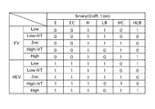
そして、前記「10の走行モード」のモード遷移制御は、統合コントローラ6により行われる。すなわち、統合コントローラ6には、要求駆動力Fdrv(アクセル開度APにより求められる。)と車速VSPとバッテリS.O.Cによる三次元空間に、図4に示すような前記10の走行モードを割り振った走行モードマップが予め設定されていて、車両走行時等においては、要求駆動力Fdrvと車速VSPとバッテリS.O.Cの各検出値により走行モードマップが検索され、要求駆動力Fdrvと車速VSPにより決まる車両動作点やバッテリ充電量に応じた最適な走行モードが選択される。なお、図4は三次元走行モードマップをバッテリS.O.Cが充分な容量域のある値で切り取ることにより、要求駆動力Fdrvと車速VSPとの二次元によりあらわした走行モードマップの一例である。
Then, the mode transition control of the “10 travel modes” is performed by the
前記走行モードマップの選択により、「EVモード」と「HEVモード」との間においてモード遷移を行う場合には、図5に示すように、エンジンEの始動・停止と、エンジンクラッチECの締結・解放に加え、後述するローブレーキLBとハイクラッチHCとハイローブレーキHLBの締結・解放制御が実行される。 When the mode transition is performed between the “EV mode” and the “HEV mode” by the selection of the travel mode map, as shown in FIG. In addition to releasing, engagement / release control of the low brake LB, high clutch HC, and high / low brake HLB, which will be described later, is executed.
また、「EVモード」の5つのモード間でのモード遷移や「HEVモード」の5つのモード間でのモード遷移を行う場合には、図5に示すON/OFF作動表にしたがって行われる。例えば、「Lowモード」は、ローブレーキLB締結・ハイクラッチHC解放・ハイローブレーキHLB締結により得られる。「Low-iVTモード」は、ローブレーキLB締結・ハイクラッチHC解放・ハイローブレーキHLB解放により得られる。「2ndモード」は、ローブレーキLB締結・ハイクラッチHC締結・ハイローブレーキHLB解放により得られる。「High-iVTモード」は、ローブレーキLB解放・ハイクラッチHC締結・ハイローブレーキHLB解放により得られる。「Highモード」は、ローブレーキLB解放・ハイクラッチHC締結・ハイローブレーキHLB締結により得られる。 Further, when mode transition between the five modes of the “EV mode” and mode transition between the five modes of the “HEV mode” are performed, they are performed according to the ON / OFF operation table shown in FIG. For example, the “Low mode” is obtained by engaging the low brake LB, releasing the high clutch HC, and engaging the high / low brake HLB. "Low-iVT mode" can be obtained by engaging low brake LB, releasing high clutch HC, releasing high low brake HLB. The “2nd mode” is obtained by engaging the low brake LB, high clutch HC, and high / low brake HLB. "High-iVT mode" can be obtained by releasing the low brake LB, engaging the high clutch HC, and releasing the high / low brake HLB. "High mode" is obtained by releasing the low brake LB, engaging the high clutch HC, and engaging the high / low brake HLB.
これらのモード遷移制御のうち、例えば、エンジンEの始動・停止とクラッチやブレーキの締結・解放が同時に必要な場合や複数のクラッチやブレーキの締結・解放が必要な場合等においては、決められた手順にしたがったシーケンス制御により行われる。 Among these mode transition controls, for example, when engine E start / stop and clutch / brake engagement / release are required at the same time, or when multiple clutches / brakes need to be engaged / released, etc. It is performed by sequence control according to the procedure.
次に、作用を説明する。 Next, the operation will be described.
[再加速対応モード遷移制御処理]
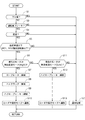
図6は実施例1の統合コントローラ6において実行される再加速対応モード遷移制御処理の流れを示すフローチャートであり、以下、各ステップについて説明する(再加速対応モード遷移制御手段)。
[Re-acceleration compatible mode transition control processing]
FIG. 6 is a flowchart showing the flow of the reacceleration compatible mode transition control process executed in the
ステップS1では、走行路面が下り坂であるか否かを判断し、YESの場合はステップS2へ移行し、NOの場合はステップS3へ移行する。ここで、下り坂判断は、例えば、車両に取り付けられた傾斜センサなどからのセンサ信号により、下り坂傾斜角が下り坂判断しきい値以上である場合に走行路面が下り坂であると判断する。 In step S1, it is determined whether or not the road surface is downhill. If YES, the process proceeds to step S2, and if NO, the process proceeds to step S3. Here, the downhill determination is, for example, based on a sensor signal from an inclination sensor attached to the vehicle, when the downhill inclination angle is equal to or greater than a downhill determination threshold value, it is determined that the traveling road surface is a downhill. .
ステップS2では、ステップS1での下り坂であるとの判断に基づき、通常のモード遷移制御が実行され、リターンへ移行する。ここで、通常のモード遷移制御とは、10の走行モードのうち最適な走行モードを、走行モードマップ上で車両の運転点(要求駆動力Fdrvと車速VSPにより決まる点)とバッテリS.O.Cにより選択し、現在選択されている走行モードとは異なる走行モードの領域へ車両の運転点が入ったとき、2つの走行モード間でモード遷移制御を行うことをいう。 In step S2, normal mode transition control is executed based on the determination that the vehicle is a downhill in step S1, and the process proceeds to return. Here, with normal mode transition control, the optimal driving mode among the ten driving modes is selected on the driving mode map based on the driving point of the vehicle (the point determined by the required driving force Fdrv and the vehicle speed VSP) and the battery SOC. When the driving point of the vehicle enters a region of a travel mode different from the currently selected travel mode, mode transition control is performed between the two travel modes.
ステップS3では、ステップS1での下り坂ではないとの判断に基づき、運転者によるブレーキ操作時か否かを判断し、YESの場合はステップS4へ移行し、NOの場合はステップS2へ移行する。つまり、車両減速の判断を、運転者によるブレーキ操作の有無により判断するようにしている。 In step S3, based on the determination that the vehicle is not downhill in step S1, it is determined whether or not the driver is operating a brake. If YES, the process proceeds to step S4. If NO, the process proceeds to step S2. . That is, the vehicle deceleration is determined based on the presence or absence of a brake operation by the driver.
ステップS4では、ステップS3での運転者によるブレーキ操作時であるとの判断に基づき、変速(モード遷移)が許可される車両状態か否かが判断され、YESの場合はステップS5へ移行し、NOの場合はステップS2へ移行する。ここで、変速が許可されない車両状態とは、例えば、走行中で既にモード遷移が実行されている場合や車両が既に停止状態にある場合をいい、これ以外の場合を変速が許可される車両状態とする。 In step S4, based on the determination that the driver is operating the brake in step S3, it is determined whether or not the vehicle is in a state where shifting (mode transition) is permitted. If YES, the process proceeds to step S5. If NO, the process proceeds to step S2. Here, the vehicle state in which gear shifting is not permitted refers to, for example, a case where mode transition is already being performed during traveling or a vehicle is already in a stopped state, and a vehicle state in which gear shifting is permitted in other cases. And
ステップS5では、ステップS4での変速(モード遷移)が許可される車両状態であるとの判断に基づき、車速が設定車速(例えば、5km/h程度)以下で、且つ、第1モータジェネレータ回転数N1と第2モータジェネレータ回転数N2とが設定回転数(例えば、500rpm程度)以下であるか否かが判断され、YESの場合はステップS6へ移行し、NOの場合はステップS2へ移行する。 In step S5, the vehicle speed is equal to or lower than the set vehicle speed (for example, about 5 km / h) based on the determination that the shift (mode transition) is permitted in step S4, and the first motor generator rotational speed is set. It is determined whether N1 and the second motor generator rotational speed N2 are equal to or lower than a set rotational speed (for example, about 500 rpm). If YES, the process proceeds to step S6, and if NO, the process proceeds to step S2.
ステップS6では、ステップS5において車速条件とモータジェネレータ回転数条件とが成立しているとの判断に基づき、現在選択されている走行モードが「EV-High-iVTモード」、または、「HEV-High-iVTモード」か否かが判断され、YESの場合はステップS7へ移行し、NOの場合はステップS11へ移行する。 In step S6, based on the determination that the vehicle speed condition and the motor generator rotation speed condition are satisfied in step S5, the currently selected travel mode is “EV-High-iVT mode” or “HEV-High -iVT mode "is determined. If YES, the process proceeds to step S7, and if NO, the process proceeds to step S11.
ステップS7では、ステップS6において「EV-High-iVTモード」、または、「HEV-High-iVTモード」であるとの判断に基づき、ローブレーキLBを締結し、ステップS8へ移行する。 In step S7, the low brake LB is engaged based on the determination that the "EV-High-iVT mode" or "HEV-High-iVT mode" is set in step S6, and the process proceeds to step S8.
ステップS8では、ステップS6において「EV-High-iVTモード」、または、「HEV-High-iVTモード」であるとの判断に基づき、ハイクラッチHCを解放し、ステップS9へ移行する。 In step S8, based on the determination in step S6 that the vehicle is in the “EV-High-iVT mode” or “HEV-High-iVT mode”, the high clutch HC is released, and the process proceeds to step S9.
ステップS9では、ステップS6において「EV-High-iVTモード」、または、「HEV-High-iVTモード」であるとの判断に基づき、ハイローブレーキHLBを締結し、ステップS10へ移行する。 In step S9, the high / low brake HLB is engaged based on the determination in step S6 that the vehicle is in the “EV-High-iVT mode” or “HEV-High-iVT mode”, and the process proceeds to step S10.
ステップS10では、ステップS7でのローブレーキLB締結、ステップS8でのハイクラッチHC解放、ステップS9でのハイローブレーキHLB締結により、「EV-High-iVTモード」または「HEV-High-iVTモード」から、「EV-Lowモード」または「HEV-Lowモード」へのモード遷移を実行し、リターンへ移行する。 In step S10, from the “EV-High-iVT mode” or “HEV-High-iVT mode” by engaging the low brake LB in step S7, releasing the high clutch HC in step S8, and engaging the high / low brake HLB in step S9. Executes mode transition to “EV-Low mode” or “HEV-Low mode” and shifts to return.
ステップS11では、ステップS6での「EV-High-iVTモード」、または、「HEV-High-iVTモード」ではないとの判断に基づき、現在選択されている走行モードが「EV-Low-iVTモード」、または、「HEV-Low-iVTモード」か否かが判断され、YESの場合はステップS12へ移行し、NOの場合はステップS2へ移行する。 In step S11, based on the determination that it is not the “EV-High-iVT mode” or “HEV-High-iVT mode” in step S6, the currently selected travel mode is “EV-Low-iVT mode”. ”Or“ HEV-Low-iVT mode ”is determined. If YES, the process proceeds to step S12. If NO, the process proceeds to step S2.
ステップS12では、ステップS11において「EV-Low-iVTモード」、または、「HEV-Low-iVTモード」であるとの判断に基づき、ハイローブレーキHLBを締結し、ステップS13へ移行する。 In step S12, the high / low brake HLB is engaged based on the determination that the "EV-Low-iVT mode" or the "HEV-Low-iVT mode" is set in step S11, and the process proceeds to step S13.
ステップS13では、ステップS12でのハイローブレーキHLB締結により、「EV-Low-iVTモード」または「HEV-Low-iVTモード」から、「EV-Lowモード」または「HEV-Lowモード」へのモード遷移を実行し、リターンへ移行する。 In step S13, the mode transition from “EV-Low-iVT mode” or “HEV-Low-iVT mode” to “EV-Low mode” or “HEV-Low mode” by engaging the high / low brake HLB in step S12. And move to return.
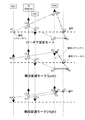
[通常モード遷移制御による再加速時の課題]
共線図上に4つ以上の入出力要素が配列される差動装置を有し、前記入出力要素のうちの内側に配列される2つの要素の一方にエンジンからの入力を、他方に駆動系統への出力部材をそれぞれ割り当てると共に、前記内側の要素の両外側に配列される2つの要素にそれぞれ第1モータジェネレータMG1と第2モータジェネレータMG2とを連結し、前記出力部材の外側要素と第2モータジェネレータの連結要素をクラッチ1で締結した「無段変速モード(High)」と、前記クラッチ1を解放し、別の要素をブレーキ2で固定した「無段変速モード(Low)」と、両モータジェネレータのどちらか一方の要素、または、別の要素のいずれかをブレーキ1で固定する「ローギヤ固定モード」を備えた駆動装置において、高速走行から減速後に再加速を行う場合を考える。
[Problems during re-acceleration by normal mode transition control]
It has a differential device in which four or more input / output elements are arranged on a nomogram, and the input from the engine is driven to one of the two elements arranged inside the input / output element, and the other is driven Each of the output members to the system is assigned, and the first motor generator MG1 and the second motor generator MG2 are connected to the two elements arranged on both outer sides of the inner element, respectively. 2 “Continuously variable transmission mode (High)” in which the connecting element of the motor generator is engaged with the clutch 1; “Continuously variable transmission mode (Low)” in which the
まず、図7は「ローギヤ固定モード」と「無段変速モード(Low)」と「無段変速モード(High)」における入出力4要素のトルクの関係を表した共線図である。
「ローギヤ固定モード」においては、第2モータジェネレータMG2が正トルクを出すことで、エンジンINをアシストすることになり、第1モータジェネレータMG1が負のトルクを出すことでエンジン出力の一部を発電に回すことができる。
「無段変速モード(Low)」においては、基本的に第1モータジェネレータMG1が正トルク、第2モータジェネレータMG2が負トルクを出すことでエンジン出力が出力軸OUTに伝達される。
「無段変速モード(High)」においては、基本的に第1モータジェネレータMG1が負トルク、第2モータジェネレータMG2が正トルクを出すことでエンジン出力が出力軸OUTに伝達される。
First, FIG. 7 is a collinear diagram showing the relationship of torque of the four input / output elements in the “low gear fixed mode”, “continuously variable transmission mode (Low)”, and “continuously variable transmission mode (High)”.
In the “low gear fixed mode”, the second motor generator MG2 generates positive torque to assist the engine IN, and the first motor generator MG1 generates negative torque to generate part of the engine output. Can be turned to.
In the “continuously variable transmission mode (Low)”, the engine output is transmitted to the output shaft OUT by basically generating the positive torque from the first motor generator MG1 and the negative torque from the second motor generator MG2.
In the “continuously variable transmission mode (High)”, the engine output is transmitted to the output shaft OUT basically by the first motor generator MG1 producing negative torque and the second motor generator MG2 producing positive torque.
よって、高速走行時は、エンジンINの入力をその両外側の2要素に連結された第1モータジェネレータMG1と第2モータジェネレータMG2で支えることにより駆動力が出力される(図7の「無段変速モード(High)」)。減速中には、ブレーキ2を締結し、クラッチ1を解放することによりモード遷移する(図7の「無段変速モード(Low)」)。さらに、再加速中には、ブレーキ1を締結することによりモード遷移する(図7の「ローギヤ固定モード」)。
Therefore, during high speed running, the driving force is output by supporting the input of the engine IN with the first motor generator MG1 and the second motor generator MG2 connected to the two elements on both sides (see “Steplessly” in FIG. 7). Shift mode (High) ”). During deceleration, the mode is changed by engaging the
したがって、図7の共線図において、第2リングギヤR2側を解放した「無段変速モード(Low)」から「ローギヤ固定モード」へとモード遷移する場合、第1モータジェネレータMG1は正トルクを出しながら回転数をゼロにする必要があるため、第1モータジェネレータMG1の回転数低下からブレーキ1の締結までに時間を要し、再加速が滑らかに行われないという課題がある。
Therefore, in the collinear diagram of FIG. 7, when the mode transition is made from the “continuous speed change mode (Low)” with the second ring gear R2 side released to the “low gear fixed mode”, the first motor generator MG1 produces a positive torque. However, since it is necessary to reduce the rotation speed to zero, it takes time from the decrease in the rotation speed of the first motor generator MG1 to the engagement of the
[再加速対応モード遷移制御作用]
これに対し、実施例1では、高速走行からの減速時に、車速が設定車速以下で、かつ、両モータジェネレータMG1,MG2の回転数が設定回転数以下の場合、強制的にローブレーキLB,ハイクラッチHC,ハイローブレーキHLBを締結・解放することにより、「無段変速モード(High)」あるいは「無段変速モード(Low)」から「ローギヤ固定モード」へモード遷移することで、上記課題を解決した。
[Re-acceleration mode transition control action]
On the other hand, in the first embodiment, when the vehicle speed is lower than the set vehicle speed and the motor generators MG1 and MG2 are below the set speed when decelerating from high speed running, the low brake LB, high By engaging / disengaging the clutch HC and high / low brake HLB, the above-mentioned problems can be solved by changing the mode from "Continuously Variable Mode (High)" or "Continuously Variable Mode (Low)" to "Low Gear Fixed Mode". did.
すなわち、高速走行からの減速時に、車速が設定車速以下で、かつ、両モータジェネレータMG1,MG2の回転数が設定回転数以下の場合であって、現在の走行モードが「EV-High-iVTモード」あるいは「HEV-High-iVTモード」である場合、図6のフローチャートにおいて、ステップS1→ステップS3→ステップS4→ステップS5→ステップS6→ステップS7→ステップS8→ステップS9→ステップS10へと進む流れとなり、「EV-High-iVTモード」あるいは「HEV-High-iVTモード」で解放されているローブレーキLBを締結し、「EV-High-iVTモード」あるいは「HEV-High-iVTモード」で締結されているハイクラッチHCを解放し、「EV-High-iVTモード」あるいは「HEV-High-iVTモード」で解放されているハイローブレーキHLBを締結することで、強制的に「無段変速モード(High)」から「ローギヤ固定モード」へモード遷移される。 That is, when decelerating from high-speed driving, the vehicle speed is lower than the set vehicle speed, and the rotation speeds of both motor generators MG1, MG2 are lower than the set rotation speed, and the current driving mode is `` EV-High-iVT mode Or “HEV-High-iVT mode”, the flow proceeds to step S1, step S3, step S4, step S5, step S6, step S7, step S8, step S9, and step S10 in the flowchart of FIG. The low brake LB released in the “EV-High-iVT mode” or “HEV-High-iVT mode” is concluded, and the “EV-High-iVT mode” or “HEV-High-iVT mode” is concluded. By releasing the high clutch HC that has been released and engaging the high-low brake HLB that has been released in the “EV-High-iVT mode” or “HEV-High-iVT mode”, the “continuously variable transmission mode ( High Is the mode transition to the "low gear fixed mode" from ".
また、高速走行からの減速時に、車速が設定車速以下で、かつ、両モータジェネレータMG1,MG2の回転数が設定回転数以下の場合であって、現在の走行モードが「EV-Low-iVTモード」あるいは「HEV-Low-iVTモード」である場合、図6のフローチャートにおいて、ステップS1→ステップS3→ステップS4→ステップS5→ステップS6→ステップS11→ステップS12→ステップS13へと進む流れとなり、「EV-Low-iVTモード」あるいは「HEV-Low-iVTモード」で解放されているハイローブレーキHLBを締結することで、強制的に「無段変速モード(Low)」から「ローギヤ固定モード」へモード遷移される。
Also, when decelerating from high-speed driving, the vehicle speed is lower than the set vehicle speed, and the rotation speed of both motor generators MG1 and MG2 is lower than the set rotation speed, and the current driving mode is `` EV-Low-iVT mode Or “HEV-Low-iVT mode”, in the flowchart of FIG. 6, the flow proceeds from
ここで、図8に示すタイムチャートを用いて、高速走行から減速して再加速する場合のモード遷移タイミングと加速度特性とを従来制御(=走行マップを用いた通常のモード遷移制御)と本発明制御とで比較する。 Here, using the time chart shown in FIG. 8, conventional mode control (= normal mode transition control using a travel map) and the present invention for mode transition timing and acceleration characteristics when decelerating and reaccelerating from high speed travel and the present invention. Compare with control.
まず、従来制御の場合、目標車速が減速から加速に移行する再加速要求時点t1より遅れたt2の時点まで「無段変速モード(High)」が維持され、t2の時点で走行モードマップ上で隣接する「無段変速モード(High)」から「無段変速モード(Low)」へとモード遷移し、さらに、t3の時点で「無段変速モード(Low)」から「ローギヤ固定モード」へモード遷移することになる。つまり、再加速の際には、「無段変速モード(Low)」からのスタートとなり、駆動力要求が大きい場合には、上記のように第1モータジェネレータMG1の回転数低下とハイローブレーキHLBの締結のために応答遅れがある「ローギヤ固定モード」へのモード遷移が必要となり、図8に示すように、加速度特性に段差が生じて滑らかな再加速ができない。 First, in the case of conventional control, the “continuously variable transmission mode (High)” is maintained until the time t2 that is delayed from the reacceleration request time t1 when the target vehicle speed shifts from deceleration to acceleration. The mode transitions from the adjacent “continuously variable transmission mode (High)” to “continuously variable transmission mode (Low)”, and at t3, the mode changes from “continuously variable transmission mode (Low)” to “low gear fixed mode”. Will transition. That is, at the time of re-acceleration, it starts from “continuously variable transmission mode (Low)”, and when the driving force demand is large, as described above, the decrease in the rotational speed of the first motor generator MG1 and the high / low brake HLB A mode transition to the “low gear fixed mode” with a response delay is required for fastening, and as shown in FIG. 8, a step is generated in the acceleration characteristic, and smooth re-acceleration cannot be performed.
一方、本発明制御の場合、目標車速が減速から加速に移行する再加速要求時点t1より先行するt0の時点で「無段変速モード(High)」から「ローギヤ固定モード」へモード遷移することになる。つまり、再加速の際のモード遷移が無く、再加速要求時点t1からの後の再加速に備え、「ローギヤ固定モード」へモード遷移を既に終えているため、図8に示すように、再加速要求時点t1の直後から滑らかに立ち上がる加速度特性を得ることができる。さらに、駆動力要求が大きくても、エンジンEの出力トルクを第2モータジェネレータMG2の正トルクでアシストすることで大きな駆動力を出せる「ローギヤ固定モード」により要求に応えることができる。なお、図8のハッチングで示す領域が従来制御に対する本発明制御の加速度増大代となる。 On the other hand, in the case of the control according to the present invention, the mode transition from “continuously variable transmission mode (High)” to “low gear fixed mode” is performed at time t0 preceding the reacceleration request time t1 when the target vehicle speed shifts from deceleration to acceleration. Become. In other words, there is no mode transition at the time of reacceleration, and the mode transition to the “low gear fixed mode” has already been completed in preparation for the reacceleration after the reacceleration request time t1, so as shown in FIG. An acceleration characteristic that rises smoothly immediately after the request time t1 can be obtained. Furthermore, even if the driving force request is large, the request can be met by the “low gear fixed mode” that can output a large driving force by assisting the output torque of the engine E with the positive torque of the second motor generator MG2. In addition, the area | region shown by hatching of FIG. 8 becomes the acceleration increase margin of this invention control with respect to conventional control.
次に、効果を説明する。
実施例1のハイブリッド車のモード遷移制御装置にあっては、下記に列挙する効果を得ることができる。
Next, the effect will be described.
In the hybrid vehicle mode transition control apparatus of the first embodiment, the following effects can be obtained.
(1) 共線図上に4つ以上の入出力要素が配列される差動装置を有し、前記入出力要素のうちの内側に配列される2つの要素の一方にエンジンEからの入力を、他方に駆動系統への出力軸OUTをそれぞれ割り当てると共に、前記内側の要素の両外側に配列される2つの要素にそれぞれ第1モータジェネレータMG1と第2モータジェネレータMG2とを連結した駆動力合成変速機TMを備えたハイブリッド車において、走行モードとして、少なくとも無段変速比により走行する「無段変速モード」と、前記差動装置の回転要素を変速機ケースに固定することでロー側の固定変速比により走行する「ローギヤ固定モード」と、を有し、前記「無段変速モード」を選択しての車両減速時、車速が設定車速以下になると、強制的に「無段変速モード」から「ローギヤ固定モード」へモード遷移する再加速対応モード遷移制御手段を設けたため、「無段変速モード」を選択しての車両減速後に再加速を行う走行時、スムーズで良好な再加速性を得ることができる。 (1) It has a differential device in which four or more input / output elements are arranged on the nomograph, and an input from the engine E is input to one of the two elements arranged inside the input / output elements. In addition, the output shaft OUT to the drive system is assigned to the other, and the first motor generator MG1 and the second motor generator MG2 are connected to the two elements arranged on both outer sides of the inner element, respectively. In a hybrid vehicle equipped with the machine TM, as a driving mode, a “continuously variable transmission mode” in which the vehicle travels at least at a continuously variable transmission ratio and a fixed shift on the low side by fixing the rotating element of the differential device to the transmission case When the vehicle speed drops below the set vehicle speed when the vehicle is decelerated by selecting the “continuously variable transmission mode”, the “continuously variable transmission mode” is changed to “ Low gear Re-acceleration-compatible mode transition control means that switches to the `` constant mode '' is provided, so that smooth and good re-acceleration can be obtained when the vehicle is re-accelerated after deceleration by selecting the `` continuously variable transmission mode ''. it can.
(2) 前記走行モードとして、ハイ側無段変速比の要求時に選択される「ハイ側無段変速モード」と、ロー側無段変速比の要求時に選択される「ロー側無段変速モード」と、ロー側固定変速比の要求時に選択される「ローギヤ固定モード」と、を有し、前記再加速対応モード遷移制御手段は、「ハイ側無段変速モード」あるいは「ロー側無段変速モード」を選択しての車両減速時、車速が設定車速以下になると、強制的に「ローギヤ固定モード」にモード遷移するため、「ハイ側無段変速モード」を選択しての車両減速時には、「ロー側無段変速モード」を経過することなく直接「ローギヤ固定モード」にモード遷移することで、「ハイ側無段変速モード」と「ロー側無段変速モード」とのうち、何れのモードが車両減速時に選択されていたとしても、車両減速時後に再加速時にスムーズで良好な再加速性を得ることができる。 (2) “High-side continuously variable transmission mode” selected when the high-side continuously variable transmission ratio is requested as the travel mode, and “Low-side continuously variable transmission mode” selected when the low-side continuously variable transmission ratio is required. And a “low-gear fixed mode” selected when the low-side fixed gear ratio is requested, and the re-acceleration compatible mode transition control means is configured to select either “high-side continuously variable transmission mode” or “low-side continuously variable transmission mode”. When the vehicle decelerates when selecting `` '', if the vehicle speed falls below the set vehicle speed, the mode is forcibly shifted to `` Low gear fixed mode ''. By changing the mode directly to the "Low gear fixed mode" without passing through the "Low side continuously variable transmission mode", any of the "High side continuously variable transmission mode" or "Low side continuously variable transmission mode" Suppose that it was selected when the vehicle decelerated However, smooth and good reacceleration can be obtained during reacceleration after vehicle deceleration.
(3) 前記再加速対応モード遷移制御手段は、「ハイ側無段変速モード」あるいは「ロー側無段変速モード」を選択しての車両減速時、車速が設定車速以下であり、かつ、両モータジェネレータMG1,MG2の回転数が設定回転数以下になると、強制的に「ローギヤ固定モード」にモード遷移するため、「ローギヤ固定モード」へのモード遷移においてハイローブレーキHLBを締結するために必要である第1モータジェネレータMG1の回転数低下が速やかに行われ、「ローギヤ固定モード」への強制的なモード遷移を短時間にて応答良く行うことができる。 (3) The re-acceleration compatible mode transition control means is configured such that when the vehicle is decelerated by selecting the “high-side continuously variable transmission mode” or the “low-side continuously variable transmission mode”, the vehicle speed is equal to or less than the set vehicle speed, and both When the motor generators MG1 and MG2 are below the set speed, the mode is forcibly changed to the “low gear fixed mode”. This is necessary to engage the high / low brake HLB in the mode transition to the “low gear fixed mode”. The speed reduction of a certain first motor generator MG1 is promptly performed, and forced mode transition to the “low gear fixed mode” can be performed in a short time with good response.
(4) 前記再加速対応モード遷移制御手段は、下り坂を検出した場合、車両減速時において強制的に「ローギヤ固定モード」へ遷移する再加速対応モード遷移制御を禁止するため、運転者の意図に合致した違和感のない運転性を確保することができる。
すなわち、下り坂での減速走行の場合、その後、ブレーキ操作を解除するだけでアクセル操作を行うことなく再加速に移行することができる。このため、強制的に「ローギヤ固定モード」へ遷移しても、すぐに「無段変速モード」等へ戻す必要があり、不要なモード遷移を防止する意味でも「無段変速モード」を維持していた方が、駆動力変動が懸念されるモード遷移の頻度を少なくすることができる。
(4) When the re-acceleration-compatible mode transition control means detects a downhill, the re-acceleration-compatible mode transition control means forbids the re-acceleration-compatible mode transition control that forcibly shifts to the “low gear fixed mode” during vehicle deceleration. It is possible to ensure driving performance that does not have a sense of incongruity.
That is, in the case of decelerating traveling on a downhill, it is possible to shift to reacceleration without performing the accelerator operation only by releasing the brake operation thereafter. For this reason, even if the mode is forcibly changed to the “low gear fixed mode”, it is necessary to immediately return to the “continuously variable transmission mode” or the like, and the “continuously variable transmission mode” is maintained in order to prevent unnecessary mode transitions. If so, the frequency of mode transition, which is a concern about fluctuations in driving force, can be reduced.
(5) 前記再加速対応モード遷移制御手段は、運転者のブレーキ操作による車両減速を検出した場合にのみ、車両減速時において強制的にローギヤ固定モードへ遷移する再加速対応モード遷移制御を実行するため、運転者の意図に合致した違和感のない運転性を確保することができる。
すなわち、例えば、アクセル足離しによる車両減速時、強制的な「ローギヤ固定モード」へのモード遷移が実行されると、運転者にとっては予期せぬモード遷移であり、違和感を持つ。これに対し、運転者が自らブレーキ操作しているときに強制的な「ローギヤ固定モード」へのモード遷移が実行されても、ブレーキ操作に対応したモード遷移として違和感無く許容できる。
(5) The re-acceleration-compatible mode transition control means executes re-acceleration-compatible mode transition control that forcibly shifts to the low gear fixed mode when the vehicle is decelerated only when vehicle deceleration due to the driver's braking operation is detected. For this reason, it is possible to ensure driving performance without a sense of incongruity that matches the driver's intention.
That is, for example, when a forced mode transition to the “low gear fixed mode” is executed when the vehicle decelerates due to the release of the accelerator pedal, it is an unexpected mode transition for the driver, and the driver feels uncomfortable. On the other hand, even if the mode transition to the “low gear fixed mode” is forcibly performed when the driver performs the brake operation himself, the mode transition corresponding to the brake operation can be allowed without any sense of incongruity.
(6) 前記駆動力合成変速機TMは、第1遊星歯車PG1,第2遊星歯車PG2,第3遊星歯車PG3で構成され、エンジンEと第1モータジェネレータMG1と第2モータジェネレータMG2と出力軸OUTとが連結された差動装置と、複数の走行モードを得るために設けられたローブレーキLB,ハイクラッチHC,ハイローブレーキHLBと、を有し、前記走行モードは、予め要求駆動力Fdrvと車速VSPとバッテリS.O.Cに応じて各走行モードを割り振り設定した走行モードマップと、検出された要求駆動力Fdrvと車速VSPとバッテリS.O.Cによる車両運転点とを用い、走行モードマップ上での車両運転点が所属する走行モード領域を検索することにより決定し、前記「ハイ側無段変速モード」は、ローブレーキLB解放,ハイクラッチHC締結,ハイローブレーキHLB解放により、ハイ側無段変速比を得る走行モードであり、前記「ロー側無段変速モード」は、ローブレーキLB締結,ハイクラッチHC解放,ハイローブレーキHLB解放により、ロー側無段変速比を得る走行モードであり、前記「ローギヤ固定モード」は、ローブレーキLB締結,ハイクラッチHC解放,ハイローブレーキHLB締結により、ロー側固定変速比を得る走行モードであるため、減速からの再加速時、通常のモード遷移制御を適用した場合に比べ、応答良く、かつ、滑らかに立ち上がる加速度特性により、高い駆動力要求に対応する優れた再加速性を達成することができる。
すなわち、減速からの再加速時、通常のモード遷移制御を適用した場合、「ハイ側無段変速モード」→「ロー側無段変速モード」→「ローギヤ固定モード」というモード遷移になると共に、「ロー側無段変速モード」→「ローギヤ固定モード」については第1モータジェネレータMG1の回転数の低下を待ってハイローブレーキHLBを固定する必要があり、時間がかかるため、再加速が段差的な加速度特性により滑らかに行われない。
(6) The driving force synthesis transmission TM is composed of a first planetary gear PG1, a second planetary gear PG2, and a third planetary gear PG3, and includes an engine E, a first motor generator MG1, a second motor generator MG2, and an output shaft. A differential device connected to OUT, and a low brake LB, a high clutch HC, and a high / low brake HLB provided to obtain a plurality of driving modes, and the driving mode includes a required driving force Fdrv in advance. A vehicle driving point on the driving mode map using a driving mode map in which each driving mode is allocated and set according to the vehicle speed VSP and the battery SOC, and the detected driving force Fdrv, the vehicle speed VSP, and the vehicle driving point by the battery SOC. The “high-side continuously variable transmission mode” determines the high-side continuously variable transmission ratio by releasing the low brake LB, engaging the high clutch HC, and releasing the high-low brake HLB. The “low-side continuously variable transmission mode” is a traveling mode that obtains a low-side continuously variable transmission ratio by engaging the low brake LB, releasing the high clutch HC, and releasing the high-low brake HLB. "Mode" is a driving mode that obtains the low-side fixed gear ratio by engaging the low brake LB, releasing the high clutch HC, and engaging the high / low brake HLB, and therefore when normal mode transition control is applied during re-acceleration from deceleration. Compared with the acceleration characteristic that rises smoothly with good response, it is possible to achieve excellent reacceleration performance corresponding to high driving force requirements.
That is, when normal mode transition control is applied at the time of re-acceleration from deceleration, the mode transition is `` high-side continuously variable transmission mode '' → `` low-side continuously variable transmission mode '' → `` low gear fixed mode '' For “Low-side continuously variable transmission mode” → “Low gear fixed mode”, it is necessary to fix the high / low brake HLB after waiting for the rotation speed of the first motor generator MG1 to decrease. Not smooth due to characteristics.
以上、本発明のハイブリッド車のモード遷移制御装置を実施例1に基づき説明してきたが、具体的な構成については、この実施例1に限られるものではなく、特許請求の範囲の各請求項に係る発明の要旨を逸脱しない限り、設計の変更や追加等は許容される。 As mentioned above, although the mode transition control apparatus of the hybrid vehicle of this invention has been demonstrated based on Example 1, it is not restricted to this Example 1 about a concrete structure, Each claim of a Claim Design changes and additions are allowed without departing from the gist of the invention.
実施例1では、車両減速をブレーキ操作により判断する例を示したが、例えば、車速センサや前後Gセンサからの信号に基づいて車両減速度を検出して車両減速を判断しても良いし、また、アクセル足離し操作により車両減速を判断しても良いし、アクセル足離し操作とブレーキ操作とを組み合わせて車両減速を判断しても良い。 In the first embodiment, an example in which vehicle deceleration is determined by a brake operation is shown. For example, vehicle deceleration may be detected by detecting vehicle deceleration based on signals from a vehicle speed sensor and a front and rear G sensor, Further, the vehicle deceleration may be determined by the accelerator release operation, or the vehicle deceleration may be determined by combining the accelerator release operation and the brake operation.
実施例1のハイブリッド車のモード遷移制御装置は、3つのシングルピニオン型遊星歯車により構成された差動装置を有する駆動力合成変速機の例を示したが、例えば、特開2003−32808号公報等に記載されているようにラビニョウ型遊星歯車により構成された差動装置を有する駆動力合成変速機にも適用することができるし、それ以外の差動装置であっても、少なくとも1つの無段変速モードとローギヤ固定モードを有する駆動力合成変速機を搭載したハイブリッド車には適用することができる。 The mode transition control device of the hybrid vehicle according to the first embodiment is an example of a driving force combining transmission having a differential gear configured by three single pinion type planetary gears. For example, Japanese Patent Laid-Open No. 2003-32808 Can be applied to a driving force synthesizing transmission having a differential device composed of Ravigneaux-type planetary gears as described in the above, and at least one non-differentiating device can also be used. The present invention can be applied to a hybrid vehicle equipped with a driving force synthesis transmission having a step shifting mode and a low gear fixed mode.
E エンジン
MG1 第1モータジェネレータ
MG2 第2モータジェネレータ
OUT 出力軸(出力部材)
PG1 第1遊星歯車
PG2 第2遊星歯車
PG3 第3遊星歯車
EC エンジンクラッチ
LB ローブレーキ
HC ハイクラッチ
HLB ハイローブレーキ
1 エンジンコントローラ
2 モータコントローラ
3 インバータ
4 バッテリ
5 油圧制御装置
6 統合コントローラ
7 アクセル開度センサ
8 車速センサ
9 エンジン回転数センサ
10 第1モータジェネレータ回転数センサ
11 第2モータジェネレータ回転数センサ
12 第3リングギヤ回転数センサ
E engine
MG1 1st motor generator
MG2 Second motor generator
OUT Output shaft (output member)
PG1 1st planetary gear
PG2 2nd planetary gear
PG3 3rd planetary gear
EC engine clutch
LB Low brake
HC high clutch
HLB High /
Claims (6)
走行モードとして、少なくとも無段変速比により走行する無段変速モードと、前記差動装置の回転要素を変速機ケースに固定することでロー側の固定変速比により走行するローギヤ固定モードと、を有し、
前記無段変速モードを選択しての車両減速時、車速が設定車速以下になると、強制的に無段変速モードからローギヤ固定モードへモード遷移する再加速対応モード遷移制御手段を設けたことを特徴とするハイブリッド車のモード遷移制御装置。 It has a differential device in which four or more input / output elements are arranged on a nomogram, and the input from the engine is driven to one of the two elements arranged inside the input / output element, and the other is driven In a hybrid vehicle provided with driving force combining transmissions, each of which is assigned an output member to a system, and has a first motor generator and a second motor generator connected to two elements arranged on both outer sides of the inner element ,
The travel mode includes a continuously variable transmission mode that travels at least at a continuously variable transmission ratio, and a low gear fixed mode that travels at a fixed transmission ratio on the low side by fixing the rotating element of the differential device to the transmission case. And
When the vehicle is decelerated with the continuously variable transmission mode selected, there is provided a re-acceleration-compatible mode transition control means for forcibly shifting the mode from the continuously variable transmission mode to the low gear fixed mode when the vehicle speed becomes a set vehicle speed or less. A mode transition control device for a hybrid vehicle.
前記走行モードとして、ハイ側無段変速比の要求時に選択されるハイ側無段変速モードと、ロー側無段変速比の要求時に選択されるロー側無段変速モードと、ロー側固定変速比の要求時に選択されるローギヤ固定モードと、を有し、
前記再加速対応モード遷移制御手段は、ハイ側無段変速モードあるいはロー側無段変速モードを選択しての車両減速時、車速が設定車速以下になると、強制的にローギヤ固定モードにモード遷移することを特徴とするハイブリッド車のモード遷移制御装置。 In the hybrid vehicle mode transition control device according to claim 1,
As the travel mode, a high-side continuously variable transmission mode selected when a high-side continuously variable transmission ratio is required, a low-side continuously variable transmission mode selected when a low-side continuously variable transmission ratio is required, and a low-side fixed transmission ratio. Low gear fixed mode selected at the time of request,
The re-acceleration compatible mode transition control means forcibly transitions to the low gear fixed mode when the vehicle speed is lower than the set vehicle speed during vehicle deceleration with the high-side continuously variable transmission mode or the low-side continuously variable transmission mode selected. A mode transition control device for a hybrid vehicle.
前記再加速対応モード遷移制御手段は、ハイ側無段変速モードあるいはロー側無段変速モードを選択しての車両減速時、車速が設定車速以下であり、かつ、両モータジェネレータの回転数が設定回転数以下になると、強制的にローギヤ固定モードにモード遷移することを特徴とするハイブリッド車のモード遷移制御装置。 In the hybrid vehicle mode transition control device according to claim 2,
The re-acceleration compatible mode transition control means is configured such that when the vehicle is decelerated by selecting the high-side continuously variable transmission mode or the low-side continuously variable transmission mode, the vehicle speed is equal to or less than the set vehicle speed, and the rotation speeds of both motor generators are set. A mode transition control device for a hybrid vehicle, characterized in that mode transition is forcedly made to a low gear fixed mode when the rotational speed is below the rotational speed.
前記再加速対応モード遷移制御手段は、下り坂を検出した場合、車両減速時において強制的にローギヤ固定モードへ遷移する再加速対応モード遷移制御を禁止することを特徴とするハイブリッド車のモード遷移制御装置。 In the hybrid vehicle mode transition control device according to any one of claims 1 to 3,
The re-acceleration compatible mode transition control means forbids re-acceleration compatible mode transition control that forcibly transitions to the low gear fixed mode when the vehicle decelerates when detecting a downhill. apparatus.
前記再加速対応モード遷移制御手段は、運転者のブレーキ操作による車両減速を検出した場合にのみ、車両減速時において強制的にローギヤ固定モードへ遷移する再加速対応モード遷移制御を実行することを特徴とするハイブリッド車のモード遷移制御装置。 In the hybrid vehicle mode transition control device according to any one of claims 1 to 4,
The re-acceleration responsive mode transition control means executes re-acceleration responsive mode transition control that forcibly transitions to the low gear fixed mode during vehicle deceleration only when vehicle deceleration due to a driver's braking operation is detected. A mode transition control device for a hybrid vehicle.
前記駆動力合成変速機は、第1遊星歯車,第2遊星歯車,第3遊星歯車で構成され、エンジンと第1モータジェネレータと第2モータジェネレータと出力部材とが連結された差動装置と、複数の走行モードを得るために設けられた第1摩擦締結要素,第2摩擦締結要素,第3摩擦締結要素と、を有し、
前記走行モードは、予め要求駆動力と車速とバッテリ容量に応じて各走行モードを割り振り設定した走行モードマップと、検出された要求駆動力と車速とバッテリ容量による車両運転点とを用い、走行モードマップ上での車両運転点が所属する走行モード領域を検索することにより決定し、
前記ハイ側無段変速モードは、前記第1摩擦締結要素を解放し、前記第2摩擦締結要素を締結し、前記第3摩擦締結要素を解放することで、ハイ側無段変速比を得る走行モードであり、
前記ロー側無段変速モードは、前記第1摩擦締結要素を締結し、前記第2摩擦締結要素を解放し、前記第3摩擦締結要素を解放することで、ロー側無段変速比を得る走行モードであり、
前記ローギヤ固定モードは、前記第1摩擦締結要素を締結し、前記第2摩擦締結要素を解放し、前記第3摩擦締結要素を締結することで、ロー側固定変速比を得る走行モードであることを特徴とするハイブリッド車のモード遷移制御装置。 In the hybrid vehicle mode transition control device according to any one of claims 1 to 5,
The driving force combining transmission is composed of a first planetary gear, a second planetary gear, and a third planetary gear, and a differential device in which an engine, a first motor generator, a second motor generator, and an output member are connected; A first friction engagement element, a second friction engagement element, and a third friction engagement element provided to obtain a plurality of travel modes;
The travel mode uses a travel mode map in which each travel mode is allocated and set in advance according to the required driving force, vehicle speed, and battery capacity, and the detected driving force, the vehicle speed, and the vehicle operating point based on the battery capacity. Determined by searching the driving mode area to which the vehicle driving point belongs on the map,
In the high-side continuously variable transmission mode, the first friction engagement element is released, the second friction engagement element is engaged, and the third friction engagement element is released to obtain a high-side continuously variable transmission ratio. Mode
In the low-side continuously variable transmission mode, the first frictional engagement element is engaged, the second frictional engagement element is released, and the third frictional engagement element is released to obtain a low-side continuously variable transmission ratio. Mode
The low gear fixed mode is a travel mode in which the first friction engagement element is engaged, the second friction engagement element is released, and the third friction engagement element is engaged to obtain a low-side fixed transmission ratio. A mode transition control device for a hybrid vehicle characterized by the above.
Priority Applications (1)
| Application Number | Priority Date | Filing Date | Title |
|---|---|---|---|
| JP2004111377A JP4228969B2 (en) | 2004-04-05 | 2004-04-05 | Hybrid vehicle mode transition control device |
Applications Claiming Priority (1)
| Application Number | Priority Date | Filing Date | Title |
|---|---|---|---|
| JP2004111377A JP4228969B2 (en) | 2004-04-05 | 2004-04-05 | Hybrid vehicle mode transition control device |
Publications (2)
| Publication Number | Publication Date |
|---|---|
| JP2005291476A true JP2005291476A (en) | 2005-10-20 |
| JP4228969B2 JP4228969B2 (en) | 2009-02-25 |
Family
ID=35324618
Family Applications (1)
| Application Number | Title | Priority Date | Filing Date |
|---|---|---|---|
| JP2004111377A Expired - Fee Related JP4228969B2 (en) | 2004-04-05 | 2004-04-05 | Hybrid vehicle mode transition control device |
Country Status (1)
| Country | Link |
|---|---|
| JP (1) | JP4228969B2 (en) |
Cited By (4)
| Publication number | Priority date | Publication date | Assignee | Title |
|---|---|---|---|---|
| WO2008105194A1 (en) * | 2007-02-26 | 2008-09-04 | Aisin Aw Co., Ltd. | Hybrid drive device |
| JP2009126489A (en) * | 2007-11-28 | 2009-06-11 | Toyota Motor Corp | Control device for hybrid vehicle |
| JP2012180090A (en) * | 2008-03-28 | 2012-09-20 | Toyota Motor Corp | Control device of hybrid vehicle |
| US8414436B2 (en) | 2009-04-30 | 2013-04-09 | GM Global Technology Operations LLC | Hybrid powertrain and method of operating same |
-
2004
- 2004-04-05 JP JP2004111377A patent/JP4228969B2/en not_active Expired - Fee Related
Cited By (5)
| Publication number | Priority date | Publication date | Assignee | Title |
|---|---|---|---|---|
| WO2008105194A1 (en) * | 2007-02-26 | 2008-09-04 | Aisin Aw Co., Ltd. | Hybrid drive device |
| US8246499B2 (en) | 2007-02-26 | 2012-08-21 | Aisin Aw Co., Ltd. | Drive apparatus |
| JP2009126489A (en) * | 2007-11-28 | 2009-06-11 | Toyota Motor Corp | Control device for hybrid vehicle |
| JP2012180090A (en) * | 2008-03-28 | 2012-09-20 | Toyota Motor Corp | Control device of hybrid vehicle |
| US8414436B2 (en) | 2009-04-30 | 2013-04-09 | GM Global Technology Operations LLC | Hybrid powertrain and method of operating same |
Also Published As
| Publication number | Publication date |
|---|---|
| JP4228969B2 (en) | 2009-02-25 |
Similar Documents
| Publication | Publication Date | Title |
|---|---|---|
| JP5018445B2 (en) | Control device for vehicle power transmission device | |
| JP2007001493A (en) | Control unit for hybrid vehicle | |
| JP2006335294A (en) | Vehicle control device | |
| JP2010173493A (en) | Device for controlling vehicle power transmission device | |
| JP4144576B2 (en) | Hybrid vehicle motor heat generation avoidance control device | |
| JP2007055343A (en) | Vehicle shift control device | |
| JP6972905B2 (en) | Vehicle control device | |
| JP4135708B2 (en) | Control device for hybrid vehicle | |
| JP4135672B2 (en) | Hybrid vehicle mode transition control device | |
| JP4222301B2 (en) | Hybrid vehicle engine start control device | |
| JP4228969B2 (en) | Hybrid vehicle mode transition control device | |
| JP2006187049A (en) | Control device for hybrid vehicle | |
| JP2006017229A (en) | Hill hold control device for hybrid vehicle | |
| JP4193776B2 (en) | Hybrid vehicle drive system | |
| JP4228970B2 (en) | Hybrid vehicle mode transition control device | |
| JP4039390B2 (en) | Mode transition control device and mode transition control method for hybrid vehicle | |
| JP4144559B2 (en) | Hybrid vehicle engine reverse rotation prevention control device | |
| JP4144572B2 (en) | Mode transition control device for hybrid vehicle | |
| JP2006046577A (en) | Control device for hybrid vehicle | |
| JP4135671B2 (en) | Hybrid vehicle mode transition control device | |
| JP2007168679A (en) | Control device for hybrid vehicle | |
| JP2010167911A (en) | Control device for transmission system for vehicle | |
| JP4172431B2 (en) | Control device for hybrid vehicle | |
| JP4135693B2 (en) | Hybrid vehicle mode transition control device | |
| JP4135692B2 (en) | Control device for hybrid vehicle |
Legal Events
| Date | Code | Title | Description |
|---|---|---|---|
| RD04 | Notification of resignation of power of attorney |
Free format text: JAPANESE INTERMEDIATE CODE: A7424 Effective date: 20051117 |
|
| A621 | Written request for application examination |
Free format text: JAPANESE INTERMEDIATE CODE: A621 Effective date: 20070402 |
|
| A131 | Notification of reasons for refusal |
Free format text: JAPANESE INTERMEDIATE CODE: A131 Effective date: 20070925 |
|
| A521 | Request for written amendment filed |
Free format text: JAPANESE INTERMEDIATE CODE: A523 Effective date: 20071116 |
|
| A131 | Notification of reasons for refusal |
Free format text: JAPANESE INTERMEDIATE CODE: A131 Effective date: 20080520 |
|
| A521 | Request for written amendment filed |
Free format text: JAPANESE INTERMEDIATE CODE: A523 Effective date: 20080707 |
|
| A02 | Decision of refusal |
Free format text: JAPANESE INTERMEDIATE CODE: A02 Effective date: 20080812 |
|
| A521 | Request for written amendment filed |
Free format text: JAPANESE INTERMEDIATE CODE: A523 Effective date: 20080924 |
|
| A911 | Transfer to examiner for re-examination before appeal (zenchi) |
Free format text: JAPANESE INTERMEDIATE CODE: A911 Effective date: 20081017 |
|
| TRDD | Decision of grant or rejection written | ||
| A01 | Written decision to grant a patent or to grant a registration (utility model) |
Free format text: JAPANESE INTERMEDIATE CODE: A01 Effective date: 20081111 |
|
| A01 | Written decision to grant a patent or to grant a registration (utility model) |
Free format text: JAPANESE INTERMEDIATE CODE: A01 |
|
| A61 | First payment of annual fees (during grant procedure) |
Free format text: JAPANESE INTERMEDIATE CODE: A61 Effective date: 20081124 |
|
| R150 | Certificate of patent or registration of utility model |
Free format text: JAPANESE INTERMEDIATE CODE: R150 |
|
| FPAY | Renewal fee payment (event date is renewal date of database) |
Free format text: PAYMENT UNTIL: 20111212 Year of fee payment: 3 |
|
| FPAY | Renewal fee payment (event date is renewal date of database) |
Free format text: PAYMENT UNTIL: 20121212 Year of fee payment: 4 |
|
| FPAY | Renewal fee payment (event date is renewal date of database) |
Free format text: PAYMENT UNTIL: 20121212 Year of fee payment: 4 |
|
| FPAY | Renewal fee payment (event date is renewal date of database) |
Free format text: PAYMENT UNTIL: 20131212 Year of fee payment: 5 |
|
| LAPS | Cancellation because of no payment of annual fees |