JP2005291432A - Clip and air bag body installing structure - Google Patents
Clip and air bag body installing structure Download PDFInfo
- Publication number
- JP2005291432A JP2005291432A JP2004109833A JP2004109833A JP2005291432A JP 2005291432 A JP2005291432 A JP 2005291432A JP 2004109833 A JP2004109833 A JP 2004109833A JP 2004109833 A JP2004109833 A JP 2004109833A JP 2005291432 A JP2005291432 A JP 2005291432A
- Authority
- JP
- Japan
- Prior art keywords
- male part
- female part
- head
- female
- male
- Prior art date
- Legal status (The legal status is an assumption and is not a legal conclusion. Google has not performed a legal analysis and makes no representation as to the accuracy of the status listed.)
- Granted
Links
- 230000037431 insertion Effects 0.000 claims description 19
- 238000003780 insertion Methods 0.000 claims description 19
- 230000000149 penetrating effect Effects 0.000 claims description 3
- 238000005452 bending Methods 0.000 abstract 1
- 230000008878 coupling Effects 0.000 description 2
- 238000010168 coupling process Methods 0.000 description 2
- 238000005859 coupling reaction Methods 0.000 description 2
- 238000004519 manufacturing process Methods 0.000 description 2
- 230000005489 elastic deformation Effects 0.000 description 1
- 238000001746 injection moulding Methods 0.000 description 1
- 238000010137 moulding (plastic) Methods 0.000 description 1
- 230000035515 penetration Effects 0.000 description 1
- 230000001960 triggered effect Effects 0.000 description 1
Images


Classifications
-
- F—MECHANICAL ENGINEERING; LIGHTING; HEATING; WEAPONS; BLASTING
- F16—ENGINEERING ELEMENTS AND UNITS; GENERAL MEASURES FOR PRODUCING AND MAINTAINING EFFECTIVE FUNCTIONING OF MACHINES OR INSTALLATIONS; THERMAL INSULATION IN GENERAL
- F16B—DEVICES FOR FASTENING OR SECURING CONSTRUCTIONAL ELEMENTS OR MACHINE PARTS TOGETHER, e.g. NAILS, BOLTS, CIRCLIPS, CLAMPS, CLIPS OR WEDGES; JOINTS OR JOINTING
- F16B5/00—Joining sheets or plates, e.g. panels, to one another or to strips or bars parallel to them
- F16B5/06—Joining sheets or plates, e.g. panels, to one another or to strips or bars parallel to them by means of clamps or clips
- F16B5/0607—Joining sheets or plates, e.g. panels, to one another or to strips or bars parallel to them by means of clamps or clips joining sheets or plates to each other
- F16B5/0621—Joining sheets or plates, e.g. panels, to one another or to strips or bars parallel to them by means of clamps or clips joining sheets or plates to each other in parallel relationship
- F16B5/0642—Joining sheets or plates, e.g. panels, to one another or to strips or bars parallel to them by means of clamps or clips joining sheets or plates to each other in parallel relationship the plates being arranged one on top of the other and in full close contact with each other
-
- H—ELECTRICITY
- H01—ELECTRIC ELEMENTS
- H01H—ELECTRIC SWITCHES; RELAYS; SELECTORS; EMERGENCY PROTECTIVE DEVICES
- H01H13/00—Switches having rectilinearly-movable operating part or parts adapted for pushing or pulling in one direction only, e.g. push-button switch
- H01H13/70—Switches having rectilinearly-movable operating part or parts adapted for pushing or pulling in one direction only, e.g. push-button switch having a plurality of operating members associated with different sets of contacts, e.g. keyboard
- H01H13/83—Switches having rectilinearly-movable operating part or parts adapted for pushing or pulling in one direction only, e.g. push-button switch having a plurality of operating members associated with different sets of contacts, e.g. keyboard characterised by legends, e.g. Braille, liquid crystal displays, light emitting or optical elements
-
- H—ELECTRICITY
- H05—ELECTRIC TECHNIQUES NOT OTHERWISE PROVIDED FOR
- H05B—ELECTRIC HEATING; ELECTRIC LIGHT SOURCES NOT OTHERWISE PROVIDED FOR; CIRCUIT ARRANGEMENTS FOR ELECTRIC LIGHT SOURCES, IN GENERAL
- H05B33/00—Electroluminescent light sources
- H05B33/02—Details
- H05B33/04—Sealing arrangements, e.g. against humidity
-
- B—PERFORMING OPERATIONS; TRANSPORTING
- B60—VEHICLES IN GENERAL
- B60R—VEHICLES, VEHICLE FITTINGS, OR VEHICLE PARTS, NOT OTHERWISE PROVIDED FOR
- B60R21/00—Arrangements or fittings on vehicles for protecting or preventing injuries to occupants or pedestrians in case of accidents or other traffic risks
- B60R21/02—Occupant safety arrangements or fittings, e.g. crash pads
- B60R21/16—Inflatable occupant restraints or confinements designed to inflate upon impact or impending impact, e.g. air bags
- B60R21/20—Arrangements for storing inflatable members in their non-use or deflated condition; Arrangement or mounting of air bag modules or components
-
- F—MECHANICAL ENGINEERING; LIGHTING; HEATING; WEAPONS; BLASTING
- F16—ENGINEERING ELEMENTS AND UNITS; GENERAL MEASURES FOR PRODUCING AND MAINTAINING EFFECTIVE FUNCTIONING OF MACHINES OR INSTALLATIONS; THERMAL INSULATION IN GENERAL
- F16B—DEVICES FOR FASTENING OR SECURING CONSTRUCTIONAL ELEMENTS OR MACHINE PARTS TOGETHER, e.g. NAILS, BOLTS, CIRCLIPS, CLAMPS, CLIPS OR WEDGES; JOINTS OR JOINTING
- F16B21/00—Means for preventing relative axial movement of a pin, spigot, shaft or the like and a member surrounding it; Stud-and-socket releasable fastenings
- F16B21/06—Releasable fastening devices with snap-action
- F16B21/08—Releasable fastening devices with snap-action in which the stud, pin, or spigot has a resilient part
- F16B21/086—Releasable fastening devices with snap-action in which the stud, pin, or spigot has a resilient part the shank of the stud, pin or spigot having elevations, ribs, fins or prongs intended for deformation or tilting predominantly in a direction perpendicular to the direction of insertion
-
- H—ELECTRICITY
- H01—ELECTRIC ELEMENTS
- H01H—ELECTRIC SWITCHES; RELAYS; SELECTORS; EMERGENCY PROTECTIVE DEVICES
- H01H2219/00—Legends
- H01H2219/002—Legends replaceable; adaptable
- H01H2219/014—LED
-
- Y—GENERAL TAGGING OF NEW TECHNOLOGICAL DEVELOPMENTS; GENERAL TAGGING OF CROSS-SECTIONAL TECHNOLOGIES SPANNING OVER SEVERAL SECTIONS OF THE IPC; TECHNICAL SUBJECTS COVERED BY FORMER USPC CROSS-REFERENCE ART COLLECTIONS [XRACs] AND DIGESTS
- Y10—TECHNICAL SUBJECTS COVERED BY FORMER USPC
- Y10T—TECHNICAL SUBJECTS COVERED BY FORMER US CLASSIFICATION
- Y10T24/00—Buckles, buttons, clasps, etc.
- Y10T24/30—Trim molding fastener
- Y10T24/309—Plastic type
-
- Y—GENERAL TAGGING OF NEW TECHNOLOGICAL DEVELOPMENTS; GENERAL TAGGING OF CROSS-SECTIONAL TECHNOLOGIES SPANNING OVER SEVERAL SECTIONS OF THE IPC; TECHNICAL SUBJECTS COVERED BY FORMER USPC CROSS-REFERENCE ART COLLECTIONS [XRACs] AND DIGESTS
- Y10—TECHNICAL SUBJECTS COVERED BY FORMER USPC
- Y10T—TECHNICAL SUBJECTS COVERED BY FORMER US CLASSIFICATION
- Y10T24/00—Buckles, buttons, clasps, etc.
- Y10T24/42—Independent, headed, aperture pass-through fastener
Landscapes
- Engineering & Computer Science (AREA)
- General Engineering & Computer Science (AREA)
- Mechanical Engineering (AREA)
- Insertion Pins And Rivets (AREA)
- Air Bags (AREA)
Abstract
Description
この発明は、パネルなどに形成された取り付け穴に入れ込まれてこのパネルなどに仮留めされる雌パーツと、このように仮留めされた雌パーツ内に押し込まれてこの雌パーツの留め付け状態を強固な本留めに移行させる雄パーツとを備えてなるクリップ、および、このクリップを含んで構成されるエアバッグ本体の取り付け構造に関する。 The present invention includes a female part that is inserted into a mounting hole formed in a panel or the like and temporarily fixed to the panel or the like, and is pressed into the female part temporarily fixed in this manner and is fixed to the female part. The present invention relates to a clip including a male part that shifts to a firm main fastening, and an attachment structure of an airbag main body including the clip.
貫通穴を備えた部材のこの貫通穴に入れ込まれる挿入部と、この挿入部の入れ込まれる開口を備えたフランジとを、屈曲可能な連結片によって連結させてなり、フランジの開口を通じてかかる貫通穴に連結片を屈曲させながら挿入部を押し込ませることにより、かかる部材に留め付けられるクリップとして、特許文献1に示されるものがある。
An insertion part inserted into the through hole of a member having a through hole and a flange having an opening into which the insertion part is inserted are connected by a bendable connecting piece, and the penetration is made through the opening of the flange. There exists a thing shown by
しかるに、かかるクリップは、挿入部の前記押し込みにあたって、連結片がその屈曲中心を挿入部の挿入軸部から離れ出させるように屈曲される構造のものであるため、クリップの留め付けにあたって前記部材の貫通穴の周囲に一定のスペースを必要とさせるものであった。特に、挿入部を構成する挿入軸部の長さが長くなればなる程、連結片も長くせざるを得ず、そして、連結片が長くなれば屈曲されて外方に張り出す連結片のこの張り出し寸法も大きくなることから、かかる挿入部の長さを長くさせる要請があっても、この要請に十分に応え難いものであった。
この発明が解決しようとする主たる問題点は、雌パーツとこの雌パーツ内に押し込まれて取り付け穴へのクリップの本留め状態を作り出す雄パーツとを雄パーツのこの押し込みによって屈曲される連結片によって連結させてなるクリップにおいて、雄パーツの雌パーツ内に入り込む脚軸の長さが比較的長くなり、したがってまた連結片の長さが比較的長くなってしまう場合であっても、屈曲された連結片が徒に外方に張り出してしまわないようにする点にある。 The main problem to be solved by the present invention is that a female part and a male part that is pushed into the female part and creates a fixed state of the clip into the mounting hole are connected by a connecting piece bent by this pushing of the male part. In a clip that is connected, the length of the leg shaft that enters the female part of the male part is relatively long, and therefore, even if the length of the connecting piece is relatively long, the bent connection The point is to prevent the pieces from protruding outward.
前記問題点を解決するために、この発明にあっては、クリップが以下の(1)〜(5)の構造を備えたものとした。
(1)筒両端を解放させた筒状をなすと共に、筒上端部に外鍔を有し、かつ、筒側部に形成された割溝によって区分された筒側部の一部を外鍔に掛合面を向けた弾性掛合片としており、取り付け穴への入れ込みによって弾性掛合片を一旦内向きに撓み込ませた後の入れ込み終了位置での弾性掛合片の弾発によって前記掛合面をこの取り付け穴の入れ込み先側の穴縁部に掛合させるように構成された雌パーツと、
(2)脚軸とこの脚軸の上端に設けられた押し込み操作用の頭部とを有し、雌パーツの筒上端から脚軸をこの雌パーツ内に押し込ませることによりこの雌パーツの弾性掛合片の内向きへの撓み込みを阻止するように構成された雄パーツと、
(3)雄パーツの頭部と雌パーツの外鍔とを雄パーツの脚軸の下端が雌パーツの筒上端の直上に位置されるように連接させると共に、雄パーツの前記押し込みにより屈曲される連結片とを有しており、
(4)この連結片が、雄パーツの脚軸の軸線を挟んだ一方側において、片上端をこの雄パーツの頭部に接合させ、かつ、片下端を雌パーツの外鍔に接合させていると共に、
(5)この連結片が、雄パーツの前記押し込みにより片中間部を屈曲中心として雄パーツの脚軸の軸線を挟んだ他方側に向けられた側を屈曲外側として屈曲されるようになっている。
In order to solve the above problems, in this invention, the clip has the following structures (1) to (5).
(1) It has a cylindrical shape with both ends of the cylinder open, has an outer casing at the upper end of the cylinder, and a part of the cylindrical side section divided by the split groove formed in the cylindrical side section The hooking surface is an elastic hooking piece, and the hooking surface is formed into the mounting hole by the elastic hooking piece at the end of insertion after the elastic hooking piece is once bent inward by insertion into the mounting hole. A female part configured to be engaged with the hole edge on the insertion destination side,
(2) It has a leg shaft and a head for pushing operation provided at the upper end of the leg shaft, and the female shaft is elastically engaged by pushing the leg shaft into the female part from the upper end of the cylinder of the female part. A male part configured to prevent the inward deflection of the piece;
(3) The head of the male part and the outer flange of the female part are connected so that the lower end of the leg shaft of the male part is positioned directly above the upper end of the cylinder of the female part, and is bent by the pushing of the male part. A connecting piece,
(4) On one side of the connecting piece with the axis of the leg shaft of the male part, the upper end of the connecting part is joined to the head of the male part, and the lower end of the connecting part is joined to the outer casing of the female part. With
(5) The connecting piece is bent with the male part pushed in, with the middle portion at the bending center and the side facing the other side across the axis of the leg shaft of the male part as the bent outer side. .
雄パーツと雌パーツとはかかる連結片によって一体化されていることから、製造ラインなどにおけるクリップの管理は容易なものとされる。 Since the male part and the female part are integrated by such a connecting piece, it is easy to manage the clip in the production line or the like.
また、かかる連結片によって雄パーツは、雌パーツの筒上端の直上に脚軸の下端を位置させた状態で雌パーツに支持されることから、取り付け穴に雌パーツを入れ込みこの取り付け穴に前記のように雌パーツを掛合・仮留めさせた状態から雄パーツの頭部を利用して雄パーツを真っ直ぐに押し込むだけで雌パーツ内に雄パーツを位置あわせすることなく適切に押し込ませることができ、これによりワンタッチで雌パーツを取り付け穴に本留めさせることができる。 In addition, the male part is supported by the female part with the lower end of the leg shaft positioned just above the upper end of the cylinder of the female part by such a connecting piece. By simply pushing the male part straight using the head of the male part from the state where the female part is hooked and temporarily fastened, the male part can be pushed in properly without aligning the female part, As a result, the female part can be permanently fastened to the attachment hole with a single touch.
この雄パーツの押し込みによって連結片は屈曲されて雄パーツの頭部と雌パーツの外鍔との間に折り畳み状に挟み込みこまれるが、かかる連結片は雄パーツのこの押し込みにより片中間部を屈曲中心として雄パーツの脚軸の軸線を挟んだ他方側に向けられた側を屈曲外側として屈曲されるようになっていることから、雄パーツの頭部の外縁よりも外方に屈曲された連結片がはみ出ないようにすることができる。すなわち、クリップの本留め状態において、クリップの取り付け箇所には雄パーツの頭部の大きさ以上のスペースを必要としないようにすることができる。この結果、連結片を長く構成させることにも支障がなく、よって、この連結片によって前記のように支持される雄パーツの脚軸も支障なく長く構成させることができる。 When the male part is pushed in, the connecting piece is bent and sandwiched between the male part's head and the female part's outer cage, but the connecting piece bends the middle part of the male part. Since the side facing the other side of the leg axis of the male part as the center is bent as the bent outer side, the connection bent outward rather than the outer edge of the male part head It is possible to prevent the piece from protruding. In other words, in the fully-fastened state of the clip, it is possible to prevent a space larger than the size of the head of the male part from being required at the attachment position of the clip. As a result, there is no problem in configuring the connecting piece to be long, and therefore the leg shaft of the male part supported by the connecting piece as described above can be configured to be long without any problem.
前記連結片が雄パーツの脚軸を挟んだ両側にそれぞれ設けられているようにしておくこともある。 In some cases, the connecting pieces are provided on both sides of the leg shaft of the male part.
このようにした場合、雌パーツの外鍔の上方に雄パーツを安定的に支持することができる。 In this case, the male part can be stably supported above the outer casing of the female part.
また、前記雄パーツの頭部と雌パーツの外鍔とがそれぞれ、外縁形状を略四角形状とするように構成されていると共に、
一対の連結片の一方が、片上端を雄パーツの頭部における一つの隅部に接合させ、かつ、片下端をこの頭部の一つの隅部の直下にある雌パーツの外鍔における一つの隅部に接合させており、
かつ、一対の連結片の他方が、片上端を雄パーツの頭部における前記一つの隅部の対角位置にある隅部に接合させ、かつ、片下端を雌パーツの外鍔における前記一つの隅部の対角位置にある隅部に接合させているようにしておくこともある。
The head of the male part and the outer rim of the female part are each configured to have a substantially rectangular outer edge shape,
One of the pair of connecting pieces has one upper end joined to one corner of the head of the male part, and one lower end is connected to one corner of the female part immediately below one corner of the head. It is joined to the corner,
And the other of the pair of connecting pieces is joined to the corner at the diagonal position of the one corner of the head of the male part, and the lower end of the one of the connecting pieces is the one of the outer part of the female part. It may be made to join to the corner in the diagonal position of a corner.
このようにした場合、雌パーツの外鍔の上方に雄パーツをより安定的に支持することができる。 In this case, the male part can be supported more stably above the outer casing of the female part.
また、前記連結片の長さ方向ほぼ中程の位置に薄肉部が形成されており、かつ、この連結片の長さの2分の1となる長さが雄パーツの頭部の幅内に納まる長さとなっているようにしておくこともある。 In addition, a thin portion is formed at a position approximately in the middle of the length of the connecting piece, and a length that is a half of the length of the connecting piece is within the width of the head of the male part. Sometimes it is set to fit.
このようにした場合、雄パーツの押し込み操作によって雄パーツの脚軸が雌パーツの筒上端から雌パーツ内に真っ直ぐに入り込むようにすることができると共に、雌パーツ内に雄パーツを押し込み切った本留め状態において、屈曲されて雄パーツの頭部と雌パーツの外鍔との間に折り畳み状に挟み込まれた連結片がこの頭部の外縁の外方にはみ出すことがないようにすることができる。 In this case, the male part's leg can be pushed straight into the female part from the upper end of the female part's cylinder by pushing the male part, and the male part is pushed into the female part. In the clamped state, it is possible to prevent the connecting piece bent and sandwiched between the head of the male part and the outer casing of the female part from protruding outside the outer edge of the head. .
また、この発明にかかるエアバッグ本体の取り付け構造は、
エアバッグ装置を構成するエアバッグ本体に取り付けられたこのエアバッグ本体の取り付け用プレートに貫通状態に設けられた取り付け穴を、
自動車のボディパネルに貫通状態に設けられた取り付け穴に連通させるようにして、
両取り付け穴に前記クリップを構成する雌パーツを入れ込ませた後、この雌パーツ内に雄パーツの脚軸を押し込ませてエアバッグ本体をボディパネルに取り付けさせているようにしたものである。
Moreover, the mounting structure of the airbag body according to the present invention is as follows:
A mounting hole provided in a penetrating state on a mounting plate of the airbag body attached to the airbag body constituting the airbag device,
In order to communicate with the mounting hole provided in the through state in the body panel of the car,
The female parts constituting the clip are inserted into both mounting holes, and then the leg shaft of the male part is pushed into the female parts so that the airbag body is attached to the body panel.
かかる構造によれば、ボディパネルにエアバッグ本体を容易かつ安定的に取り付けることができる。 According to such a structure, the airbag main body can be easily and stably attached to the body panel.
この発明にかかるクリップによれば、雄パーツの脚軸の長さが比較的長くなり、したがってまた連結片の長さが比較的長くなってしまう場合であっても、屈曲された連結片が徒に外方に張り出してしまうことがない。 According to the clip of the present invention, even when the leg shaft length of the male part is relatively long and therefore the length of the coupling piece is also relatively long, the bent coupling piece is There is no overhanging outside.
また、この発明にかかるエアバッグ本体の取り付け構造によれば、ボディパネルにエアバッグ本体を容易かつ安定的に取り付けることができると共に、エアバッグ本体の取り付け用プレートの取り付け穴近傍にはクリップを構成する雄パーツの頭部分のスペースさえ確保されていればクリップの留め付けに何らの支障も生じさせることがない特長を有する。 In addition, according to the structure for attaching an airbag body according to the present invention, the airbag body can be easily and stably attached to the body panel, and a clip is formed in the vicinity of the attachment hole of the attachment plate for the airbag body. As long as the space of the head part of the male part to be secured is secured, there is a feature that does not cause any trouble in fastening the clip.
以下、図1ないし図9に基づいて、この発明を実施するための最良の形態について説明する。 The best mode for carrying out the present invention will be described below with reference to FIGS.
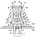
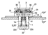
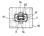
なお、ここで図1は、仮留め状態にあるクリップを、図2は、本留め状態にあるクリップを、それぞれ示している。 Here, FIG. 1 shows a clip in a temporarily fastened state, and FIG. 2 shows a clip in a fully fastened state.
この実施の形態にかかるクリップは、パネルPなどに形成された取り付け穴Hに入れ込まれてこのパネルPなどに仮留めされる雌パーツ1と、このように仮留めされた雌パーツ1内に押し込まれてこの雌パーツ1の留め付け状態を強固な本留めに移行させる雄パーツ2とを備えてなるものである。
The clip according to this embodiment is inserted into a mounting hole H formed in the panel P or the like and temporarily fixed to the panel P or the like, and the
かかるクリップは、典型的には、二以上のパネルPなどにそれぞれ形成された取り付け穴Hを連通させるようにしてこれらを重ね合わせた状態においてこの連通された取り付け穴Hに入れ込み留め付けられることで、これら二以上のパネルPなどをクリップを介して留め付け合わせるように用いられる。 Typically, such a clip is inserted into and fastened to the connected mounting hole H in a state in which the mounting holes H formed in two or more panels P or the like are connected to each other so as to communicate with each other. These two or more panels P are used so as to be fastened together via a clip.
また、この実施の形態にかかるエアバッグ本体(通常時は畳み込まれて収納されており、自動車の衝突時に生じる衝撃をトリガとしてガス放出装置から放出されるガスによって展張される袋体/一般にバッグと称される。)の取り付け構造は、
エアバッグ装置を構成するエアバッグ本体(図示は省略する。)に取り付けられたこのエアバッグ本体の取り付け用プレートP’に貫通状態に設けられた取り付け穴Hを、
自動車のボディパネルP”に貫通状態に設けられた取り付け穴Hに連通させるようにして、
両取り付け穴H、Hに前記クリップを構成する雌パーツ1を入れ込ませた後、この雌パーツ1内に雄パーツ2の脚軸を押し込ませてエアバッグ本体をボディパネルP”に取り付けさせてなるものである。
In addition, the airbag main body according to this embodiment (a bag body that is normally folded and stored and is stretched by gas discharged from the gas discharge device triggered by an impact generated at the time of automobile collision) The mounting structure is called
A mounting hole H provided in a penetrating state on a mounting plate P ′ of the airbag body attached to an airbag body (not shown) constituting the airbag device,
In order to communicate with the mounting hole H provided in the through state in the body panel P ″ of the automobile,
After the
このようにした場合、ボディパネルP”にエアバッグ本体を容易かつ安定的に取り付けることができる。すなわち、エアバッグ装置の作動時、つまり、衝突時に、エアバッグ本体の展張動作に伴ってボデイパネルPからエアバッグ本体が脱落してしまうことがない強固な取り付け状態を確保しつつ、ボデイパネルPにエアバッグ本体を容易に取り付けさせることができる。また、後述するように、雌パーツ1と雄パーツ2とを一体化させる連結片3は雌パーツ1内への雄パーツ2の脚軸20の押し込みによってこの雌パーツ1の外鍔10と雄パーツ2の頭部21との間にこの頭部21の外側にはみ出すことなく折り畳み状態で挟み込まれることから、エアバッグ本体の取り付け用プレートP’の取り付け穴H近傍にはクリップを構成する雄パーツ2の頭部21分のスペースさえ確保されていればクリップの留め付けに何らの支障も生じさせることがない特長を有する。
In this case, the airbag main body can be easily and stably attached to the body panel P ″. That is, when the airbag apparatus is operated, that is, at the time of collision, the body panel is accompanied with the expansion operation of the airbag main body. The airbag body can be easily attached to the body panel P while ensuring a strong attachment state in which the airbag body does not fall off from the P. Further, as will be described later, the
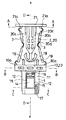
かかるクリップは、雌パーツ1と、雄パーツ2と、連結片3とを備えている。
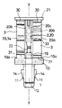
雌パーツ1は、筒両端を解放させた筒状をなすと共に、筒上端部に外鍔10を有している。
The clip includes a
The
図示の例では、かかる雌パーツ1は、幅広の一対の側板部11、11を有すると共に、この幅広の一対の側板部11、11間に幅狭の側板部12を備え、筒上端と筒下端とに共にほぼ長方形状をなす穴口を持った角筒状体の筒上端部を、板状体13の一面に一体に接合させるようにして構成されている。そして、このように接合された板状体13によって、前記外鍔10を形成させるようにしている。また、図示の例では、板状体13の他面において開放されている雌パーツ1の筒上端部の穴口18における向き合った穴縁部には、この穴縁部に沿って延びる雄パーツ2の脚軸20の押し込みをガイドする案内片19が設けられている。
In the illustrated example, the
また、かかる雌パーツ1は、筒側部に形成された割溝によって区分された筒側部の一部を外鍔10に掛合面14dを向けた弾性掛合片14としており、取り付け穴Hへの入れ込みによって弾性掛合片14を一旦内向きに撓み込ませた後の入れ込み終了位置での弾性掛合片14の弾発によって前記掛合面14dをこの取り付け穴Hの入れ込み先側の穴縁部に掛合させるように構成されている。
In addition, the
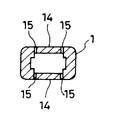
図示の例では、前記角筒状体における一対の幅広の側板部11、11にそれぞれ、前記弾性掛合片14が形成されている。具体的には、かかる幅広の側板部11には、角筒状体の筒軸に沿って延びる一対の縦向きの割溝15、15と、この一対の縦向きの割溝15、15における外鍔10側にある溝端間に亘る横向きの割溝16とが形成されており、これらの割溝15、16によって角筒状体の筒下端側を変形中心となる基部とした前記弾性掛合片14が形成されている。この弾性掛合片14の外面は、かかる基部からこの弾性掛合片14の自由端に向けて次第に高まる傾斜面14aとなっており、この傾斜面14aの最上端の先に前記掛合面14dが形成されている。すなわち、弾性掛合片14の外面部には、前記傾斜面14aの最上端を頂部14cとした掛合突部14bが形成されている。そして、図示の例にあっては、前記角筒状体の横断面外郭形状に倣った穴内郭形状を持った取り付け穴Hであって、向き合った穴内面間の間隔を一対の前記弾性掛合片14における掛合突部14bの頂部14c間の間隔よりやや小さくし、かつ、前記外鍔10の外径よりも穴径を小さくした取り付け穴Hに対し、角筒状体の筒下端を先にして外鍔10が引っかかる位置(つまり、前記入れ込み終了位置)まで雌パーツ1を入れ込ませることにより、前記傾斜面14aによって一旦角筒状体の内方に弾性掛合片14を撓み込ませた後、この弾性掛合片14に形成された前記掛合突部14bの頂部14cが取り付け穴Hの入れ込み先側の穴縁部より先に入り込んだ位置でのこの弾性掛合片14の弾発によってこの穴縁部に掛合面14dを掛合させ、これにより雌パーツ1を取り付け穴Hにワンタッチで仮留めさせるようにしてある。
In the illustrated example, the
一方、雄パーツ2は、脚軸20とこの脚軸20の上端に設けられた押し込み操作用の頭部21とを有している。
On the other hand, the
図示の例にあっては、かかる脚軸20は、板状をなす頭部21の一面のほぼ中央部に上端を一体に接合させると共に、雌パーツ1の角筒状体内に、その筒上端から押し込み入れられる太さを持つように構成されている。すなわち、図示の例にあっては、雄パーツ2の脚軸20は、雌パーツ1の角筒状体の横断面内郭形状に倣った横断面外郭形状を持った主体部20aを有しており、雌パーツ1内に押し込まれることにより雌パーツ1の幅広の側板部11の内面に接する幅広の側面20bと、雌パーツ1の幅狭の側板部12の内面に接する幅狭の側面20cとを持つように構成されている。これにより、雌パーツ1の筒上端から脚軸20をこの雌パーツ1内に押し込ませることによりこの雌パーツ1の前記弾性掛合片14の内向きへの撓み込みが阻止され、取り付け穴Hに対する雌パーツ1の留め付け状態が強固に維持される。(つまり、本留め状態が作り出される。)
In the illustrated example, the
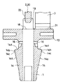
また、図示の例では、脚軸20の下端には、脚軸20の軸線に沿って延び上端を主体部20aの下端に一体に接合させたアンカー基体22aと、このアンカー基体22aの下端に下端を一体に接合させると共に自由端に向かうに連れて次第にこのアンカー基体22aから離れる向きに傾斜状に突き出し且つ自由端に頭部21に向いた掛合面22cを備えた一対のアンカーアーム22bとからなるアンカー状掛合部22が形成されている。そして図示の例にあっては、雌パーツ1内に雄パーツ2を押し込み切った位置で、雌パーツ1の幅狭の側板部12におけるこの雌パーツ1の筒下端側の内面に形成されたこの筒下端に向いた段差面17に、この押し込みによって一旦内向きに弾性変形させられたアンカーアーム22bが弾発によってその掛合面22cを下方から引っかけるようになっている。これにより図示の例にあっては、雌パーツ1内に入れ込み切られた雄パーツ2は再びこの雌パーツ1内から抜け出されることがないようにしてある。
In the illustrated example, the lower end of the
また、連結片3は、雄パーツ2の頭部21と雌パーツ1の外鍔10とを雄パーツ2の脚軸20の下端が雌パーツ1の筒上端の直上に位置されるように連接させると共に、雄パーツ2の前記押し込みにより屈曲されるように構成されている。
The connecting
図示の例にあっては、かかる連結片3によって、雄パーツ2の脚軸20の下端と雌パーツ1の筒上端の穴口18との間に間隔を開けた状態で、雌パーツ1の外鍔10の上方に雄パーツ2が支持されるようになっている。
In the illustrated example, the outer periphery of the
また、この連結片3は、雄パーツ2の脚軸20の軸線xを挟んだ一方側において、片上端30をこの雄パーツ2の頭部21に接合(図示の例では一体的につなぎ合わされている。)させ、かつ、片下端31を雌パーツ1の外鍔10に接合(図示の例では一体的につなぎ合わされている。)させていると共に、
この連結片3は、雄パーツ2の前記押し込みにより片中間部を屈曲中心32として雄パーツ2の脚軸20の軸線xを挟んだ他方側に向けられた側を屈曲外側として屈曲されるようになっている。
In addition, the connecting
The connecting
雄パーツ2と雌パーツ1とはかかる連結片3によって一体化されていることから、製造ラインなどにおけるクリップの管理は容易なものとされる。
Since the
また、かかる連結片3によって雄パーツ2は、雌パーツ1の筒上端の直上に脚軸20の下端を位置させた状態で雌パーツ1に支持されることから、取り付け穴Hに雌パーツ1を入れ込みこの取り付け穴Hに前記のように雌パーツ1を掛合・仮留めさせた状態から雄パーツ2の頭部21を利用して雄パーツ2を真っ直ぐに押し込むだけで雌パーツ1内に雄パーツ2を位置あわせすることなく適切に押し込ませることができ、これによりワンタッチで雌パーツ1を取り付け穴Hに本留めさせることができる。
Moreover, since the
この雄パーツ2の押し込みによって連結片3は屈曲されて雄パーツ2の頭部21と雌パーツ1の外鍔10との間に折り畳み状に挟み込みこまれるが、かかる連結片3は雄パーツ2のこの押し込みにより片中間部を屈曲中心32として雄パーツ2の脚軸20の軸線xを挟んだ他方側に向けられた側を屈曲外側として屈曲されるようになっていることから、雄パーツ2の頭部21の外縁よりも外方に屈曲された連結片3がはみ出ないようにすることができる。すなわち、クリップの本留め状態においては、クリップの取り付け箇所には雄パーツ2の頭部21の大きさ以上のスペースを必要としない。この結果、連結片3を長く構成させることにも支障がなく、よって、この連結片3によって前記のように支持される雄パーツ2の脚軸20も支障なく長く構成させることができる。
By pushing the
図示の例では、かかる連結片3が雄パーツ2の脚軸20を挟んだ両側にそれぞれ設けられている。
In the illustrated example, such connecting
具体的には、雄パーツ2の脚軸20の軸線xを含んだ仮想の平面yを挟んだ一方側と他方側とにそれぞれ、連結片3が設けられている。
Specifically, the connecting
これにより図示の例にあっては、雌パーツ1の外鍔10の上方に雄パーツ2を安定的に支持できるようになっている。
Thus, in the illustrated example, the
より具体的には、図示の例にあっては、雄パーツ2の脚軸20の軸線xを含んだ仮想の平面yを挟んだ一方側にある連結片3は、雄パーツ2の脚軸20の軸線xを挟んだ一方側において、片上端30をこの雄パーツ2の頭部21に接合させ、かつ、片下端31を雌パーツ1の外鍔10に接合させており、
前記仮想の平面yを挟んだ他方側にある連結片3は、雄パーツ2の脚軸20の軸線xを挟んだ他方側において、片上端30をこの雄パーツ2の頭部21に接合させ、かつ、片下端31を雌パーツ1の外鍔10に接合させている。
More specifically, in the illustrated example, the connecting
The connecting
図示の例にあっては、雄パーツ2の頭部21と雌パーツ1の外鍔10とがそれぞれ、外縁形状を略四角形状とするように構成されていると共に、
一対の連結片3の一方が、片上端30を雄パーツ2の頭部21における一つの隅部21aに接合させ、かつ、片下端31をこの頭部21の一つの隅部21aの直下にある雌パーツ1の外鍔10における一つの隅部10aに接合させており、
かつ、一対の連結片3の他方が、片上端30を雄パーツ2の頭部21における前記一つの隅部21aの対角位置にある隅部21aに接合させ、かつ、片下端31を雌パーツ1の外鍔10における前記一つの隅部10aの対角位置にある隅部10aに接合させている。
In the illustrated example, the
One of the pair of connecting
In addition, the other of the pair of connecting
これにより、図示の例にあっては、雌パーツ1の外鍔10の上方に雄パーツ2をより安定的に支持できるようになっている。
Thus, in the illustrated example, the
また、図示の例にあっては、連結片3の長さ方向ほぼ中程の位置に薄肉部33が形成されており、かつ、この連結片3の長さの2分の1となる長さが雄パーツ2の頭部21の幅内に納まる長さとなっている。
Further, in the illustrated example, the
具体的には、図示の例にあっては、連結片3は帯板状をなすように構成されていると共に、その長さ方向ほぼ中程の位置に連結片3の幅方向に亘る溝状部34を備えており、この溝状部34によって前記薄肉部33が形成されている。この溝状部34は雄パーツ2の脚軸20の軸線xを挟んだ一方側に溝口を向けており、また、この溝状部34によって形成された薄肉部33は雄パーツ2の脚軸20の軸線xを挟んだ他方側を湾曲外側とした湾曲片状をなすように構成されている。これにより、雄パーツ2を押し込み操作すると、連結片3はこの薄肉部33を屈曲中心32として雄パーツ2の脚軸20の軸線xを挟んだ他方側に向けられた側を屈曲外側として屈曲される。また、図示の例では、連結片3の片上端30と片下端31とにもそれぞれ連結片3の幅方向に亘る溝状部34が形成されており、これにより、この連結片3の片上端30と片下端31とにもそれぞれ薄肉部33が形成されている。これにより、雄パーツ2の押し込み操作によって連結片3の片中間部を前記のように円滑に屈曲できるようになっている。また、連結片3の長さの2分の1となる長さが雄パーツ2の頭部21の幅、図示の例では、外縁形状をほぼ四角形状とする雄パーツ2の頭部21の一辺の長さ内に納まる長さとなっている。
Specifically, in the illustrated example, the connecting
図示の例にあっては、連結片3の長さ方向ほぼ中程の位置にかかる薄肉部33が形成されていると共に、この連結片3の長さの2分の1となる長さが雄パーツ2の頭部21の幅内に納まる長さとなっていることから、雄パーツ2の押し込み操作によって雄パーツ2の脚軸20が雌パーツ1の筒上端から雌パーツ1内に真っ直ぐに入り込むようにすることができると共に、雌パーツ1内に雄パーツ2を押し込み切った本留め状態において、屈曲されて雄パーツ2の頭部21と雌パーツ1の外鍔10との間に折り畳み状に挟み込まれた連結片3がこの頭部21の外縁の外方にはみ出すことがないようにすることができる。
In the illustrated example, the
図示の例では、帯板状をなす連結片3は、その肉厚方向にある面を雄パーツ2の脚軸20の幅広の側面側に向けた状態で、雄パーツ2と雌パーツ1とを連結させるように構成されている。
In the example shown in the figure, the connecting
以上に説明したクリップにおける弾性変形特性を備えるべき箇所へのこの特性の付与は、典型的には、かかるクリップを射出成形などのプラスチック成型によって形成させることで容易に確保させることができる。 The imparting of this characteristic to the portion to be provided with the elastic deformation characteristic in the clip described above can be easily ensured typically by forming the clip by plastic molding such as injection molding.
1 雌パーツ
10 外鍔
14 弾性掛合片
15、16 割溝
2 雄パーツ
20 脚軸
21 頭部
3 連結片
30 片上端
31 片下端
x 軸線
P パネル
H 取り付け穴
DESCRIPTION OF
Claims (5)
脚軸とこの脚軸の上端に設けられた押し込み操作用の頭部とを有し、雌パーツの筒上端から脚軸をこの雌パーツ内に押し込ませることによりこの雌パーツの弾性掛合片の内向きへの撓み込みを阻止するように構成された雄パーツと、
雄パーツの頭部と雌パーツの外鍔とを雄パーツの脚軸の下端が雌パーツの筒上端の直上に位置されるように連接させると共に、雄パーツの前記押し込みにより屈曲される連結片とを有しており、
この連結片が、雄パーツの脚軸の軸線を挟んだ一方側において、片上端をこの雄パーツの頭部に接合させ、かつ、片下端を雌パーツの外鍔に接合させていると共に、
この連結片が、雄パーツの前記押し込みにより片中間部を屈曲中心として雄パーツの脚軸の軸線を挟んだ他方側に向けられた側を屈曲外側として屈曲されるようになっていることを特徴とするクリップ。 It has a cylindrical shape with both ends of the cylinder open, and has an outer casing at the upper end of the cylinder, and a part of the cylindrical side section divided by the split groove formed in the cylindrical side section is hooked to the outer casing. The elastic engagement piece is directed toward the mounting hole, and the elastic engagement piece is bent inward by insertion into the attachment hole, and then the engagement surface is inserted into the attachment hole by the elastic engagement piece at the insertion end position. A female part configured to hang on the side hole edge;
It has a leg shaft and a head for pushing operation provided at the upper end of the leg shaft. By pushing the leg shaft into the female part from the upper end of the cylinder of the female part, A male part configured to prevent deflection in the direction; and
The male part head and the female part outer shell are connected so that the lower end of the leg shaft of the male part is positioned directly above the upper end of the cylinder of the female part, and the connecting piece is bent by the pushing of the male part; Have
While this connecting piece is on one side across the axis of the leg shaft of the male part, the upper end of the one is joined to the head of the male part, and the lower end of the male part is joined to the outer casing of the female part,
The connecting piece is bent with the side facing toward the other side sandwiching the axis of the leg shaft of the male part with the middle part of the male part as the bending center by the pushing of the male part. And clip.
一対の連結片の一方が、片上端を雄パーツの頭部における一つの隅部に接合させ、かつ、片下端をこの頭部の一つの隅部の直下にある雌パーツの外鍔における一つの隅部に接合させており、
かつ、一対の連結片の他方が、片上端を雄パーツの頭部における前記一つの隅部の対角位置にある隅部に接合させ、かつ、片下端を雌パーツの外鍔における前記一つの隅部の対角位置にある隅部に接合させていることを特徴とする請求項2記載のクリップ。 The head of the male part and the outer casing of the female part are each configured to have a substantially rectangular outer edge shape,
One of the pair of connecting pieces has one upper end joined to one corner of the head of the male part, and one lower end is connected to one corner of the female part immediately below one corner of the head. It is joined to the corner,
And the other of the pair of connecting pieces is joined to the corner at the diagonal position of the one corner of the head of the male part, and the lower end of the one of the connecting pieces is the one of the outer part of the female part. The clip according to claim 2, wherein the clip is joined to a corner at a diagonal position of the corner.
自動車のボディパネルに貫通状態に設けられた取り付け穴に連通させるようにして、
両取り付け穴に請求項1から請求項4のいずれか1項に記載のクリップを構成する雌パーツを入れ込ませた後、この雌パーツ内に雄パーツの脚軸を押し込ませてエアバッグ本体をボディパネルに取り付けさせていることを特徴とするエアバッグ本体の取り付け構造。 A mounting hole provided in a penetrating state on a mounting plate of the airbag body attached to the airbag body constituting the airbag device,
In order to communicate with the mounting hole provided in the through state in the body panel of the car,
After inserting the female part which comprises the clip of any one of Claims 1-4 in both attachment holes, the leg axis | shaft of a male part is pushed in in this female part, and an airbag main body is inserted. A structure for attaching an air bag body characterized by being attached to a body panel.
Priority Applications (3)
| Application Number | Priority Date | Filing Date | Title |
|---|---|---|---|
| JP2004109833A JP4376680B2 (en) | 2004-04-02 | 2004-04-02 | Clip and airbag body mounting structure |
| US11/094,316 US7219400B2 (en) | 2004-04-02 | 2005-03-31 | Clip and airbag body installation structure |
| KR1020050027637A KR100680490B1 (en) | 2004-04-02 | 2005-04-01 | Attachment structure of clip and airbag body |
Applications Claiming Priority (1)
| Application Number | Priority Date | Filing Date | Title |
|---|---|---|---|
| JP2004109833A JP4376680B2 (en) | 2004-04-02 | 2004-04-02 | Clip and airbag body mounting structure |
Publications (2)
| Publication Number | Publication Date |
|---|---|
| JP2005291432A true JP2005291432A (en) | 2005-10-20 |
| JP4376680B2 JP4376680B2 (en) | 2009-12-02 |
Family
ID=35052614
Family Applications (1)
| Application Number | Title | Priority Date | Filing Date |
|---|---|---|---|
| JP2004109833A Expired - Fee Related JP4376680B2 (en) | 2004-04-02 | 2004-04-02 | Clip and airbag body mounting structure |
Country Status (3)
| Country | Link |
|---|---|
| US (1) | US7219400B2 (en) |
| JP (1) | JP4376680B2 (en) |
| KR (1) | KR100680490B1 (en) |
Cited By (3)
| Publication number | Priority date | Publication date | Assignee | Title |
|---|---|---|---|---|
| JP2010539420A (en) * | 2007-09-21 | 2010-12-16 | アー ライモント エ カンパニュイ | Device for attaching two attachment members to one support member |
| CN101522478B (en) * | 2006-10-09 | 2011-05-04 | 关键安全体系股份有限公司 | Airbag Module Mounting System |
| KR20210112033A (en) * | 2020-03-04 | 2021-09-14 | 주식회사 니프코코리아 | Under cover fastening clip |
Families Citing this family (12)
| Publication number | Priority date | Publication date | Assignee | Title |
|---|---|---|---|---|
| DE102005062242B3 (en) * | 2005-12-24 | 2007-08-30 | A. Raymond Et Cie | Device for attaching an attachment to a support part |
| JP2009051272A (en) * | 2007-08-24 | 2009-03-12 | Nippon Pop Rivets & Fasteners Ltd | Trim clip of trim for curtain side airbag |
| CN101861259B (en) * | 2007-11-16 | 2012-06-13 | 百乐仕株式会社 | Clip for air bag |
| WO2011001943A1 (en) * | 2009-06-29 | 2011-01-06 | 株式会社ニフコ | Clip and clip device |
| CN101959386A (en) * | 2009-07-17 | 2011-01-26 | 鸿富锦精密工业(深圳)有限公司 | Fastener |
| WO2012096103A1 (en) * | 2011-01-11 | 2012-07-19 | オートリブ ディベロップメント エービー | Cover for airbag device, and airbag device |
| TWI548548B (en) | 2014-01-16 | 2016-09-11 | 提愛思科技股份有限公司 | Mounting member and seat equipped with airbag module |
| US11692571B2 (en) | 2019-04-08 | 2023-07-04 | Volvo Car Corporation | Clip assembly for holding a component during a vehicle assembly/disassembly process |
| DE102020110407A1 (en) * | 2020-04-16 | 2021-10-21 | Illinois Tool Works Inc. | Fastening device for fastening a component to a carrier component |
| CN113623302B (en) * | 2021-07-01 | 2022-12-27 | 济宁兴发弹簧有限公司 | Multi-section damping air spring fastener |
| CN113482234B (en) * | 2021-07-22 | 2022-08-19 | 江苏宝鹏建筑工业化材料有限公司 | Fireproof autoclaved aerated concrete slab |
| US11686332B1 (en) * | 2022-07-27 | 2023-06-27 | NIFCO America Corporation | Accordion clip |
Family Cites Families (8)
| Publication number | Priority date | Publication date | Assignee | Title |
|---|---|---|---|---|
| US3074134A (en) * | 1961-04-14 | 1963-01-22 | Thompson Ind Inc | Fastening means |
| JPS5218564A (en) | 1975-08-01 | 1977-02-12 | Kojima Press Co Ltd | Stud |
| JP2532721B2 (en) | 1990-05-25 | 1996-09-11 | 日本電信電話株式会社 | Optical amplifier |
| JPH07233807A (en) * | 1994-02-22 | 1995-09-05 | Nifco Inc | Clip |
| JP2001317515A (en) * | 2000-05-11 | 2001-11-16 | Nippon Pop Rivets & Fasteners Ltd | Holding apparatus |
| US6431585B1 (en) * | 2000-10-05 | 2002-08-13 | Lear Corporation | Dual stage fastener |
| US6851710B2 (en) * | 2001-03-06 | 2005-02-08 | Autoliv Asp, Inc. | Apparatus and method for rapid airbag component installation |
| US6659701B1 (en) * | 2002-10-17 | 2003-12-09 | Illinois Tool Works Inc. | Rocker panel fastener |
-
2004
- 2004-04-02 JP JP2004109833A patent/JP4376680B2/en not_active Expired - Fee Related
-
2005
- 2005-03-31 US US11/094,316 patent/US7219400B2/en not_active Expired - Fee Related
- 2005-04-01 KR KR1020050027637A patent/KR100680490B1/en not_active Expired - Fee Related
Cited By (4)
| Publication number | Priority date | Publication date | Assignee | Title |
|---|---|---|---|---|
| CN101522478B (en) * | 2006-10-09 | 2011-05-04 | 关键安全体系股份有限公司 | Airbag Module Mounting System |
| JP2010539420A (en) * | 2007-09-21 | 2010-12-16 | アー ライモント エ カンパニュイ | Device for attaching two attachment members to one support member |
| KR20210112033A (en) * | 2020-03-04 | 2021-09-14 | 주식회사 니프코코리아 | Under cover fastening clip |
| KR102361302B1 (en) * | 2020-03-04 | 2022-02-11 | 주식회사 니프코코리아 | Under cover fastening clip |
Also Published As
| Publication number | Publication date |
|---|---|
| KR20060045435A (en) | 2006-05-17 |
| US20050217083A1 (en) | 2005-10-06 |
| JP4376680B2 (en) | 2009-12-02 |
| KR100680490B1 (en) | 2007-02-08 |
| US7219400B2 (en) | 2007-05-22 |
Similar Documents
| Publication | Publication Date | Title |
|---|---|---|
| JP4376680B2 (en) | Clip and airbag body mounting structure | |
| JP5243749B2 (en) | Clip and support member | |
| CN104136277B (en) | Tether clip and trim attachment device including same | |
| US20090191025A1 (en) | Fastener | |
| JP4213381B2 (en) | clip | |
| JP6466310B2 (en) | clip | |
| US20170294768A1 (en) | Electrical box support | |
| JP2013064492A (en) | Clip | |
| JP2010090991A (en) | Hole plug | |
| CN102405354A (en) | Fastener with ribbed flange | |
| KR20100045994A (en) | An integral clip of plastic material | |
| CN104806615A (en) | Tether clip and pillar garnish mounting structure | |
| JP4950674B2 (en) | clip | |
| JP2010229637A (en) | Exterior material end mounting bracket and exterior material mounting bracket with exterior material end mounting bracket | |
| JP2006044529A (en) | Door inner panel for vehicle | |
| JP2007110806A (en) | Fitting | |
| WO2015080153A1 (en) | Retainer | |
| JP3115378U (en) | Hang and display | |
| JPH1162921A (en) | Screw grommet for wall hole | |
| JPH0842536A (en) | clip | |
| JP2009257508A (en) | Two piece clip | |
| JP2006214479A (en) | Resin material mating structure | |
| JP2006125571A (en) | clip | |
| JP2017009098A (en) | Fastener | |
| JP2004270874A (en) | Fastener |
Legal Events
| Date | Code | Title | Description |
|---|---|---|---|
| A621 | Written request for application examination |
Free format text: JAPANESE INTERMEDIATE CODE: A621 Effective date: 20061225 |
|
| A977 | Report on retrieval |
Free format text: JAPANESE INTERMEDIATE CODE: A971007 Effective date: 20090220 |
|
| TRDD | Decision of grant or rejection written | ||
| A01 | Written decision to grant a patent or to grant a registration (utility model) |
Free format text: JAPANESE INTERMEDIATE CODE: A01 Effective date: 20090901 |
|
| A01 | Written decision to grant a patent or to grant a registration (utility model) |
Free format text: JAPANESE INTERMEDIATE CODE: A01 |
|
| A61 | First payment of annual fees (during grant procedure) |
Free format text: JAPANESE INTERMEDIATE CODE: A61 Effective date: 20090909 |
|
| R150 | Certificate of patent or registration of utility model |
Free format text: JAPANESE INTERMEDIATE CODE: R150 |
|
| FPAY | Renewal fee payment (event date is renewal date of database) |
Free format text: PAYMENT UNTIL: 20120918 Year of fee payment: 3 |
|
| FPAY | Renewal fee payment (event date is renewal date of database) |
Free format text: PAYMENT UNTIL: 20120918 Year of fee payment: 3 |
|
| FPAY | Renewal fee payment (event date is renewal date of database) |
Free format text: PAYMENT UNTIL: 20120918 Year of fee payment: 3 |
|
| FPAY | Renewal fee payment (event date is renewal date of database) |
Free format text: PAYMENT UNTIL: 20120918 Year of fee payment: 3 |
|
| FPAY | Renewal fee payment (event date is renewal date of database) |
Free format text: PAYMENT UNTIL: 20130918 Year of fee payment: 4 |
|
| R250 | Receipt of annual fees |
Free format text: JAPANESE INTERMEDIATE CODE: R250 |
|
| LAPS | Cancellation because of no payment of annual fees |