JP2005291423A - Synchronizing device for transmission - Google Patents
Synchronizing device for transmission Download PDFInfo
- Publication number
- JP2005291423A JP2005291423A JP2004109562A JP2004109562A JP2005291423A JP 2005291423 A JP2005291423 A JP 2005291423A JP 2004109562 A JP2004109562 A JP 2004109562A JP 2004109562 A JP2004109562 A JP 2004109562A JP 2005291423 A JP2005291423 A JP 2005291423A
- Authority
- JP
- Japan
- Prior art keywords
- hub
- sleeve
- synchronization
- spline
- ring
- Prior art date
- Legal status (The legal status is an assumption and is not a legal conclusion. Google has not performed a legal analysis and makes no representation as to the accuracy of the status listed.)
- Pending
Links
- 230000005540 biological transmission Effects 0.000 title claims abstract description 37
- 238000003825 pressing Methods 0.000 claims abstract description 14
- 238000000034 method Methods 0.000 claims abstract description 5
- 230000001105 regulatory effect Effects 0.000 claims abstract 5
- 230000001360 synchronised effect Effects 0.000 claims description 9
- 210000000078 claw Anatomy 0.000 claims description 7
- 230000006866 deterioration Effects 0.000 abstract description 13
- 230000007935 neutral effect Effects 0.000 description 6
- 230000018109 developmental process Effects 0.000 description 2
- 230000004323 axial length Effects 0.000 description 1
- 230000000694 effects Effects 0.000 description 1
- 239000000446 fuel Substances 0.000 description 1
- 238000009434 installation Methods 0.000 description 1
- 238000004519 manufacturing process Methods 0.000 description 1
- 239000000463 material Substances 0.000 description 1
- 239000013585 weight reducing agent Substances 0.000 description 1
Images

Classifications
-
- F—MECHANICAL ENGINEERING; LIGHTING; HEATING; WEAPONS; BLASTING
- F16—ENGINEERING ELEMENTS AND UNITS; GENERAL MEASURES FOR PRODUCING AND MAINTAINING EFFECTIVE FUNCTIONING OF MACHINES OR INSTALLATIONS; THERMAL INSULATION IN GENERAL
- F16D—COUPLINGS FOR TRANSMITTING ROTATION; CLUTCHES; BRAKES
- F16D11/00—Clutches in which the members have interengaging parts
- F16D11/02—Clutches in which the members have interengaging parts disengaged by a contact of a part mounted on the clutch with a stationarily-mounted member
- F16D11/06—Clutches in which the members have interengaging parts disengaged by a contact of a part mounted on the clutch with a stationarily-mounted member with clutching members movable otherwise than only axially, e.g. rotatable keys
-
- F—MECHANICAL ENGINEERING; LIGHTING; HEATING; WEAPONS; BLASTING
- F16—ENGINEERING ELEMENTS AND UNITS; GENERAL MEASURES FOR PRODUCING AND MAINTAINING EFFECTIVE FUNCTIONING OF MACHINES OR INSTALLATIONS; THERMAL INSULATION IN GENERAL
- F16D—COUPLINGS FOR TRANSMITTING ROTATION; CLUTCHES; BRAKES
- F16D23/00—Details of mechanically-actuated clutches not specific for one distinct type
- F16D23/02—Arrangements for synchronisation, also for power-operated clutches
- F16D23/04—Arrangements for synchronisation, also for power-operated clutches with an additional friction clutch
- F16D23/06—Arrangements for synchronisation, also for power-operated clutches with an additional friction clutch and a blocking mechanism preventing the engagement of the main clutch prior to synchronisation
Landscapes
- Engineering & Computer Science (AREA)
- General Engineering & Computer Science (AREA)
- Mechanical Engineering (AREA)
- Mechanical Operated Clutches (AREA)
Abstract
Description
本発明は、車両用手動変速機の変速操作(ギヤ切り替え)時に、スリーブから同期リングへの押圧力を、同期リングで発生する摩擦トルクによって増大させ、同期能力を高めることが可能な変速機用同期装置に関するものである。 The present invention is for a transmission that can increase the synchronization capability by increasing the pressing force from the sleeve to the synchronization ring during the gear shifting operation (gear switching) of the vehicle manual transmission by the friction torque generated in the synchronization ring. The present invention relates to a synchronization device.
従来、この種の変速機用同期装置としては、同期リングで発生する摩擦トルクをスリーブまたは推力板の斜面を介してハブに伝達する過程で、ハブとスリーブまたは推力板との間で生ずるスラスト、すなわち自己サーボ作用によって同期能力を高める作用を得るようにしたものが知られている(たとえば、特許文献1参照)。 Conventionally, this type of transmission synchronizer includes a thrust generated between the hub and the sleeve or thrust plate in the process of transmitting the friction torque generated in the synchronization ring to the hub via the slope of the sleeve or thrust plate. That is, there is known one that obtains an action of increasing the synchronization capability by a self-servo action (see, for example, Patent Document 1).
しかしながら、ハブとスリーブとの間でスラストを発生させる方式(特許文献1の第1図乃至第12図)にあっては、同期作用終了後にスリーブおよび同期リングをハブ(特許文献1のスリーブ受け4に相当)に対して若干回転させて、スリーブとハブとが特許文献1の第11図のように相対回転できない状態にしてから、スリーブとギヤ側のスプライン(特許文献1のスプライン21、31に相当)とを噛み合わせるようにしている。
However, in the method of generating thrust between the hub and the sleeve (FIGS. 1 to 12 of Patent Document 1), the sleeve and the synchronization ring are connected to the hub (the sleeve receiver 4 of Patent Document 1) after the synchronization action is completed. The sleeve and the hub are not allowed to rotate relative to each other as shown in FIG. 11 of
このため、スリーブ受けには傾斜面45が形成され、この傾斜面45に沿ってスリーブ6の傾斜面66が移動するようになっており、この間、スリーブ6が軸方向に無駄な移動をしなければならない。すなわち、同期作用とは関係ない軸方向の移動を余計にすることになり、結果としてスリーブ6を動かす操作ストロークまたは操作力が大きくなるので、操作フィーリングを悪化させる。 For this reason, an inclined surface 45 is formed on the sleeve receiver, and the inclined surface 66 of the sleeve 6 moves along the inclined surface 45. During this time, the sleeve 6 must move unnecessarily in the axial direction. I must. That is, the movement in the axial direction that is not related to the synchronization action becomes unnecessary, and as a result, the operation stroke or the operation force for moving the sleeve 6 is increased, so that the operation feeling is deteriorated.
一方、ハブと推力板との間でスラストを発生させる方式(特許文献1の第13図乃至第20図)にあっては、第20図の(ハ)乃至(ニ)間のように同期が終了してからスリーブ6がギヤ側のスプライン21と噛み合うまでの間、同期リング5がスラスト板10とともにハブ(同公報におけるスリーブ受け4)に対して相対回転可能であるため、この間において同期したハブおよびスリーブと変速ギヤとの間に再び回転差が生じ、スリーブとギヤ側のスプライン61、21同士が噛み合う際に両者の衝突が起き、操作フィーリングを悪化させる。
解決しようとする問題点は、自己サーボ作用による同期性能の向上と操作フィーリングが両立できない点である。
本発明の目的は、簡単な構造で同期能力を向上させながら、操作フィーリングの悪化を防止することが可能な同期装置を提供することにある。
The problem to be solved is that the improvement of the synchronization performance by the self-servo action and the operation feeling cannot be achieved at the same time.
An object of the present invention is to provide a synchronizer capable of preventing deterioration in operation feeling while improving synchronization capability with a simple structure.
本発明は、ハブとスラストピースとの間、またはスリーブと同期リングとの間に、同期終了からスリーブが変速ギヤのスプラインと噛み合うまでの間に、両者の相対回転が起きないように規制手段を設けることを最も主要な特徴とする。
すなわち、同期リング、ハブおよびスリーブと変速ギヤとの間の同期作用が終了した段階において、同期リングは変速ギヤと一体になっているとともにスラストピースと係合しているので、ハブとスラストピースとの間、またはスリーブと同期リングとの間に、両者を係合する規制手段を設け、これを係合することによってスリーブと変速ギヤとの間において相対回転を規制してから、スリーブと変速ギヤのスプライン同士を噛み合わせるように構成した。
The present invention provides a restricting means between the hub and the thrust piece or between the sleeve and the synchronization ring so that relative rotation of the two does not occur from the end of the synchronization until the sleeve engages with the spline of the transmission gear. The most important feature is the installation.
That is, at the stage where the synchronization operation between the synchronization ring, hub and sleeve and the transmission gear is completed, the synchronization ring is integrated with the transmission gear and engaged with the thrust piece. Or between the sleeve and the synchronization ring, a restricting means for engaging both is provided, and by engaging this, the relative rotation is restricted between the sleeve and the transmission gear, and then the sleeve and the transmission gear. The splines are configured to mesh with each other.
本発明の変速機用同期装置は、簡単な構造で、同期リングに生ずる摩擦トルクを軸方向のスラストに変換して、これを同期リングを押圧する力の一部にすることで、スリーブからの押圧力に対して同期能力(摩擦トルク)を向上することを実現しながら、同期作用が終了してからスリーブと変速ギヤのスプライン同士が噛み合うまでの間において、同期リングのハブに対する相対回転が起きないので、スリーブと変速ギヤのスプライン同士が衝突することによる操作フィーリングの悪化を防止することができる。
また、同期リングのハブに対する相対回転を規制するための、スリーブの余計な軸方向の移動がないので、スリーブのストロークが増えることに起因する操作フィーリングの悪化を防止することができる。
The transmission synchronizer of the present invention has a simple structure, converts the friction torque generated in the synchronization ring into axial thrust, and uses this as part of the force that presses the synchronization ring. While realizing improved synchronization capability (friction torque) against the pressing force, the relative rotation of the synchronization ring with respect to the hub occurs between the end of the synchronization operation and the engagement between the sleeve and the spline of the transmission gear. Therefore, it is possible to prevent deterioration in operation feeling due to collision between the sleeve and the spline of the transmission gear.
Further, since there is no extra axial movement of the sleeve for restricting the relative rotation of the synchronizing ring with respect to the hub, it is possible to prevent the deterioration of the operation feeling due to an increase in the stroke of the sleeve.
以下、本発明の実施の形態に係る変速機用同期装置を、各実施例に基づき図とともに説明する。 Hereinafter, a transmission synchronization apparatus according to an embodiment of the present invention will be described with reference to the drawings based on each example.
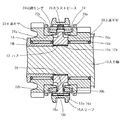
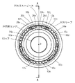
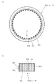
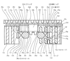
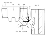
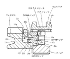
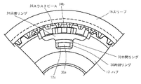
図1は、本発明装置の1実施例の主要部の断面図であって、図2におけるA−A線の断面である。図2は、図1における入力軸10と3速ギヤ20と4速ギヤ22を取り去って右側(3速ギヤ20側)から見た外観図である。
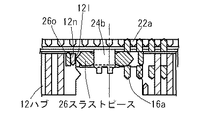
また、図3は図1の上側の要部を拡大したものである。
FIG. 1 is a cross-sectional view of the main part of one embodiment of the device of the present invention, and is a cross-section taken along line AA in FIG. FIG. 2 is an external view of the input shaft 10, the third speed gear 20, and the fourth speed gear 22 in FIG. 1 as viewed from the right side (third speed gear 20 side).
FIG. 3 is an enlarged view of the main part on the upper side of FIG.
入力軸10は、図示しないクラッチディスクを介してエンジンと連結可能になっている。
入力軸10には、ハブ12がこれらに形成したスプライン10a、12a同士で回転方向に一体に結合されており、ブッシュ14も同図中左側から圧入されて入力軸10と一体になっている。
ハブ12は、ボス部12bから外側へ延びるフランジ部12cと、このフランジ部12cの外周の環状部12dにスプライン12eが形成され、ハブ12にはスリーブ16が、これらに形成されたスプライン12e、16a同士で軸方向に相対移動可能に係合している。
The input shaft 10 can be connected to the engine via a clutch disk (not shown).
A
The
そして、入力軸10には、ベアリング18aを介して3速ギヤ20が、ブッシュ14の外側にベアリング18bを介して4速ギヤ22が、それぞれハブ12を挟むように配置され、回転自在に支持されている。
なお、3速ギヤ20および4速ギヤ22は本発明の変速ギヤを構成し、それぞれ図示しない出力軸側の相手ギヤと噛み合っており、それらを通じて車両の車輪と連結されている。
3速ギヤ20および4速ギヤ22のハブ12側には、スリーブ16のスプライン16aと噛み合うスプライン20aおよび22aと、円錐状の摩擦面20b、22bが形成してある。
A third speed gear 20 is disposed on the input shaft 10 via a
The 3rd speed gear 20 and the 4th speed gear 22 constitute a transmission gear of the present invention, which meshes with a not-shown counterpart gear on the output shaft side, and is connected to the vehicle wheel through them.
On the
スリーブ16にはこの外周にフォーク溝16bが形成され、ここに図示しないシフトフォークが摺動可能に嵌め合わされて、図示しないシフトレバーにより、これに連動してシフトフォークがスリーブ16を軸方向に移動可能になっている。
The
スリーブ16は、図1の状態のようにハブ12のスプライン12eのみに噛み合いスプライン20a、22aとは噛み合わない中立位置、図1の状態から右方へ所定量移動したときは、スリーブ16の左方部分がハブ12のスプライン12eに噛み合ったまま右方部分が3速ギヤ20のスプライン20aに噛み合う3速位置、図1の状態から左方へ所定量移動したときは、スリーブ16の右方部分がハブ12のスプライン12eに噛み合ったまま左方部分が4速ギヤ22のスプライン22aに噛み合う4速位置となるように、スリーブ16の長さおよび位置関係を設定する。
The
3速ギヤ20および4速ギヤ22とハブ12との間には、互いに同じ形状の同期リング24、24がそれぞれ配置されている。
これらの同期リング24には、摩擦面20b、22bに対応した摩擦面24a、24aが形成されており、後述するように摩擦面20bおよび24a同士と、摩擦面22bおよび24a同士が、圧接されたとき同期作用を行う。
These
両同期リング24とハブ12およびスリーブ16との間には、スラストピース26が周上の3カ所にそれぞれ配置されている。
また、両同期リング24と3個のスラストピース26との間にはスプリング28が配置されている。
A
以上のように各構成部品が配置されているが、これらの形状と各構成部品間の関係を詳述する。
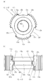
ハブ12は図4に示してあり、同図(a)が図2に対応したハブ12の外観図であり、同図(b)が(a)の上方から見たハブ12の部分拡大外観図である。
フランジ部12cから環状部12dにかけて、周上3カ所の切り欠き12fが形成してあり、該切り欠き12fの回転方向両側には斜面12g、12h、12i、12jが形成してある。
Each component is arranged as described above. The relationship between these shapes and each component will be described in detail.
The
Three
この斜面12g、12h、12i、12jは、後述するようにスラストピース26が当接してここに回転方向の力が作用すると、これを軸方向の力に変換してスラストピース26を押圧するようになっている。
環状部12dの切り欠き12fに近い部分にガイドスプライン12m、12nが形成してあり、それぞれにガイドチャンファ12o、12p、12q、12rを有する。
The
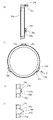
スリーブ16は図5に示してあり、同図(c)が図2に対応したスリーブ16の外観図であり、同図(d)が(c)における矢視Bを部分展開したスリーブ16の外観図である。
各スプライン16aの軸方向両端にはチャンファ16c、16dが形成されており、内周には溝16eが形成される。この溝16eの両側面は押圧面16f、16gを構成する。
The
Chamfers 16c and 16d are formed at both axial ends of each
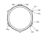
同期リング24は図6に示してあり、同図(e)が図1に対応した同期リング24の断面図であり、同図(f)が(e)を右側から見た同期リング24の外観図である。
前述のように同期リング24の内側は円錐状の摩擦面24aになっており、3速ギヤ20および4速ギヤ22の摩擦面20b、22bに対面するようにしている。
外周の3カ所に突起24bが設けられ、その回転方向両側には側面24c、24dが形成され、ハブ12に向かって軸方向に突き出されるとともに斜面24e、24fが形成され、ハブ12側の端部には3カ所中2カ所に窪み24gが、残りの1カ所に連結突起24hが形成されている。
The
As described above, the inner side of the
図6(g)は、同図(f)において窪み24gが形成された矢視Cの、同図(h)は連結突起24hが形成された同図(e)の上方からの、それぞれ部分外観を表す。
この窪み24gと連結突起24hとは、図1に示すようにハブ12を挟んで2個の同期リング24を互い違いに組み合わせることで、2カ所において一方の連結突起24hが他方の窪み24gに係合して、回転方向において連結するようになっている。
FIG. 6 (g) shows a partial appearance from the upper side of FIG. 6 (e) in which arrow 24C is formed in FIG. 6 (f), and FIG. Represents.
As shown in FIG. 1, the
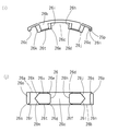
スラストピース26は図7に示してあり、同図(i)が図2に対応したスラストピース26の外観図であり、同図(j)が(i)の下方から見て展開したスラストピース26の外観図であり、それぞれ拡大図である。
スラストピース26は、(i)に示すように正面から見た全体形状は円弧状になっており、(j)に示す側面26a、26bがスリーブ16の押圧面16f、16gに対応するように挿入され、溝16eに沿って回転方向に移動可能になっている。
The
The
スラストピース26の中央部には溝26cが形成され、この溝26cは同期リング24の突起24bに対応させるとともに、チャンファ26d、26e、26f、26gと側面26j、26kが形成されている。
すなわち、側面26k、26jは同期リング24の側面24c、24dに対応して両者は摺動可能であり、チャンファ26d、26e、26f、26gは同様に同期リング24のチャンファ24e、24fに対応しており、後述の同期作用において両者は当接して押圧力の伝達をするとともに互いに摺動可能である。
A
That is, the side surfaces 26k and 26j are slidable corresponding to the side surfaces 24c and 24d of the
また、スラストピース26の両側にはスラストチャンファ26j、26k、26l、26mが形成されており、このスラストチャンファ26j、26k、26l、26mはハブ12の斜面12g、12h、12i、12jにそれぞれ対応している。
すなわち、スラストピース26は、同期リング24とハブ12とスリーブ16の間に配置されており、スリーブ16と一緒に軸方向に移動可能であるとともに同期リング24の突起24bと係合して、同期リング24とともに回転方向に移動するとスラストチャンファ26j、26k、26l、26mがハブ12の斜面12g、12h、12i、12jに当接可能である。
That is, the
そして、スラストピース26の両端部にはガイド爪26n、26oが形成され、両ガイド爪26n、26oは互いに点対称にガイドチャンファ26p、26q、26r、26sが形成されている。
さらに、スラストピース26の径方向内側には内面チャンファ26t、26uが形成され、スプリング28と当接可能になっている。
Furthermore,
スプリング28は断面が円形であって環状になっており、図1および図3に示すようにスラストピース26の内面チャンファ26t、26uと同期リング24との間に配置されている。
このため、スラストピース26が軸方向に移動する場合は、内面チャンファ26t、26uによって環状のスプリング28を三角形状に近づけるようにやや変形させながら、スプリング28の外側を通過することができる。
The
For this reason, when the
次に、図1に示した同期装置の作動を説明する。
分かり易くするため、図8に示す拡大展開図を基に説明する。
すなわち、図8は、中立状態の図1の上方から見た部分展開図であり、ハブ12から4速ギヤ22のスプライン22aまでを描いてあり、ハブ12はスプライン12eおよびガイドスプライン12m、12nの外観を、スリーブ16はスプライン22aを4本のみ描いた部分断面を、同期リングは突起24bを中心とした部分外観を、スラストピース26の断面を、スプリング28の部分外観を、それぞれ要点のみを表している。
Next, the operation of the synchronization device shown in FIG. 1 will be described.
For ease of understanding, description will be made based on the enlarged development view shown in FIG.
That is, FIG. 8 is a partial development view seen from above in FIG. 1 in a neutral state, and depicts from the
なお、図1に見るようにハブ12に面した側は、3速ギヤ20側も4速ギヤ22側と実質的に対称の形状および構造になっており、作動も基本的に同じであるので、中立状態から4速ギヤ22側への変速における作動を中心に説明する。
図8において、スラストピース26は、ハブ12の切り欠き12fの内部にあって、中立状態においては図示のように切り欠き12fに当接しているので、回転方向(図8の左右方向)には移動できない。
同期リング24は、突起24bがスラストピース26の溝26cに係合しているが、中立状態においては図に見るように回転方向に若干の隙間をもっているので、スラストピース26に対して相対回転可能である。
As shown in FIG. 1, the side facing the
In FIG. 8, the
The
以下、図9を基にスリーブ16が4速ギヤ22側へ順次移動するステップごとに説明する。なお、図9の(l)は図8を縮小して図1と同じ尺度で描いた中立状態であり、以下、スリーブ16はハブ12に対して(m)(n)(o)(p)と順次軸方向(図中の上下方向)に4速ギヤ22側へ移動する。
なお、分かり易くするため(k)から(o)にかけて、一点鎖線でハブ12の切り欠き12fの中心を描いてある。
Hereinafter, each step in which the
For the sake of clarity, the center of the
図9の(k)(l)の左側に描いた矢印は、4速ギヤ22がハブ12などに対して相対回転していることを示す。
始めに、図示しないシフトフォークによってスリーブ16が4速ギヤ22側へ押されて移動を始めると、最初にスラストピース26の内面チャンファ26uがスプリング28に当接し(図3を参照)、これを介して同期リング24を軸方向に押し始める。
すなわち、スプリング28を三角形状に変形させるのに要する力に見合った、軸方向の荷重が押圧力として同期リング24に作用する。
The arrows drawn on the left side of (k) and (l) in FIG. 9 indicate that the fourth speed gear 22 rotates relative to the
First, when the
That is, an axial load corresponding to the force required to deform the
スプリング28の張力にうち勝ってスリーブ16が4速ギヤ22側へやや進んだ状態が(n)であり、この際にスプリング28は3カ所のスラストピース26によって径方向内側へ押され、前述のようにおむすび状に変形して、スラストピース26はスプリング28の外側に乗り上げている。
The state in which the tension of the
それとともに、スプリング28から軸方向に押圧された同期リング24は、摩擦面24aが4速ギヤ22の摩擦面22bに押しつけられ、相対回転差がある両者の間に摩擦が生じる。
この摩擦トルクにより同期作用が始まり、同期リング24は4速ギヤ22につられて、スラストピース26やハブ12に対してやや相対回転する。
At the same time, the synchronizing
Synchronous action is started by this friction torque, and the
一方、このときにスラストピース26はスリーブ16とともに4速ギヤ22側へ若干移動しているので、同期リング24に作用する摩擦トルクによって同期リング24と一緒に右側方向に回転して、スラストチャンファ26jがハブ12の斜面12iに当接し、同期リング24で生じた摩擦トルクは斜面12iに作用する。
このとき、図10に示す拡大図のように、摩擦トルクTfによって軸方向の力Ftが生じ、これがスラストピース26を4速ギヤ22側へ押すスラストになる。
On the other hand, at this time, the
At this time, as shown in the enlarged view of FIG. 10, an axial force Ft is generated by the friction torque Tf, which becomes a thrust that pushes the
したがって、スリーブ16が図示しないシフトフォークから押圧される力をFmとした場合、スラストピース26が同期リング24を4速ギヤ22側へ押圧する力は、FmとFtの和になる。
すなわち、摩擦トルクTfを発生させるために同期リング24を軸方向へ押す押圧力のうち、Ftは摩擦トルクによって発生する自己サーボ力であり、Fmに付加されて同期リング24を押圧するので、自己サーボ力がない同期装置に比べて同じ摩擦トルク(同期力)を得るのに要するスリーブ16からの押圧力はFtだけ小さくて済むことになる。これが、自己サーボ力による倍力作用で同期性能が向上する原理である。
Therefore, when the force with which the
That is, of the pressing force that pushes the
図9の(l)は、同期リング24がFm+Ftで押圧されて同期作用を行って、ハブ12に対する4速ギヤ22の相対回転差がやや縮小した状態を表している。
図10および図9の(l)で分かるように、スラストピース26はチャンファ26fが同期リング24のチャンファ24eと当接し、これを軸方向に押圧している。
したがって、チャンファ26fとチャンファ24eの傾斜角を適切に設定しておくことにより、同期リング24と4速ギヤ22との間に相対回転差があって前述の摩擦トルクが生じている限り、スラストピース26は同期リング24に軸方向の進行を阻止されて4速ギヤ側へ移動することができず、同期リング24を押圧し続け、自己サーボ力Ftもそれに加勢し続ける。
FIG. 9L shows a state in which the relative rotation difference of the fourth speed gear 22 with respect to the
As can be seen from FIG. 10 and FIG. 9L, in the
Therefore, by appropriately setting the inclination angles of the
この同期作用によって、やがて、4速ギヤ22と同期リング24との回転差がなくなると、摩擦トルクが消滅するので、スラストピース26はチャンファ26fによって同期リング24を左側へ相対回転させながら4速ギヤ22側へ進行し、図9の(m)になる。(m)は、チャンファ26fがチャンファ24eを通過し終わった状態である。
Due to this synchronization action, when there is no longer a difference in rotation between the 4-speed gear 22 and the
このとき、スラストピース26のガイド爪26oのガイドチャンファ26sが、ハブ12のガイドスプライン12nのガイドチャンファ12qに当接しかかっていることが分かる。
すなわち、(m)の状態に至ると同期リング24はハブ12に対して相対回転が制約されるようになる。つまり、(m)において、ハブ12に対して同期リング24が右側方向へ相対回転しようとするとスラストピース26のスラストチャンファ26lがハブ12のチャンファ12iと当接して制約を受け、左側方向へ相対回転しようとするとスラストピース26のガイドチャンファ26sがハブ12のガイドチャンファ12qに当接して制約を受ける。
At this time, it can be seen that the
That is, when the state (m) is reached, the relative rotation of the
ここからさらにスリーブ16が4速ギヤ22側へ進行すると図9の(n)に至る。
すなわち、スリーブ16の進行とともにスラストピース26はハブ12の斜面12iに沿って移動して、これに伴いハブ12に対して右側方向へ相対回転するが、同時にスラストピース26のガイドチャンファ26sがハブ12のガイドチャンファ12qに沿って移動するので同期リング24およびスラストピース26がハブ12に対して相対回転する上で制約を受け続ける。
From this point, when the
That is, as the
さらにスリーブ16が4速ギヤ22側へ進行して、スプライン16aが4速ギヤ22のスプライン22aと噛み合った状態が図9の(o)である。
このように、スプライン16aとスプライン22aとが噛み合う直前において、同期リング24およびこれと一体になった4速ギヤと、ハブ12およびスリーブ16との間で相対回転が規制されるので、スリーブ16と4速ギヤ22の間で相対回転が起きず、スプライン16aとスプライン22aとはスムーズに噛み合いため、互いに衝突して操作フィーリングを悪化させることがない。
FIG. 9 (o) shows a state in which the
Thus, immediately before the
また、(m)から(n)にかけてスリーブ16が4速ギヤ22側へ軸方向に移動する量は通常の同期装置における移動量と同じであり、無駄な移動がないので、この間における移動量が増えて操作フィーリングが悪化することもない。
すなわち、(m)から(n)にかけてのスリーブ16の移動長さは、同期リング24および4速ギヤ22の摩擦面24a、14bの摩耗を見込んだ分を含んでおり、元々あったスリーブ16の所定移動距離の範囲内であって、このためにスリーブ16の移動距離が増えることはない。
Further, the amount of movement of the
That is, the moving length of the
図9の(k)乃至(o)は、ハブ12に対して4速ギヤ22が右側方向へ相対回転している例を示したが、逆の左側方向へ相対回転がある場合の作動について、図11で説明する。ここでも一点鎖線でハブ12の切り欠き12fの中心を描いてある。
図11は図9の(o)に対応した状態を描いてあり、(l)乃至(n)に相当する図は省略するが、これらは切り欠き12fの中心に対して対称になる。
図11は、ガイド爪26oとガイドスプライン12nとの係合が、図9の(o)とやや異なっているものの、この場合も、同期リング24はスラストピース26およびハブ12によって相対回転を規制されている。
9 (k) to (o) show an example in which the fourth speed gear 22 is relatively rotated in the right direction with respect to the
FIG. 11 illustrates a state corresponding to (o) of FIG. 9, and the drawings corresponding to (l) to (n) are omitted, but these are symmetric with respect to the center of the
11, the engagement between the guide claw 26 o and the
一方、スリーブ16を図9の(o)から(k)に戻して、さらに3速ギヤ20側へ変速操作する際に、3速ギヤ20側と4速ギヤ22側の同期リング24同士が回転方向において連結されているため、スムーズにスリーブ16を3速ギヤ20側へ移動することができる。
On the other hand, when the
以上の説明でわかるように、同じ同期容量(摩擦トルク)を得るためにスリーブ16がスラストピース26を介して同期リング24を押圧する荷重は、Ftだけ小さく済むので、Fmの値を同じで比較すると同期性能が高くなり、その倍率は以下になる。
(Fm+Ft)/Fm
As can be seen from the above description, the load with which the
(Fm + Ft) / Fm
また、同期作用が終了した後において、ハブ12に対する同期リング24の相対回転が規制されるため、スリーブ16のスプライン16aが4速ギヤ22のスプライン22aと噛み合うまでに両スプライン16a、22a間で回転差が生じないので、スムーズに噛み合うことができる。
In addition, since the relative rotation of the
さらに、ハブ12に対する同期リング24の相対回転を規制するために、スリーブ16の軸方向の移動量が増えることがないので、移動量増大に伴う操作フィーリングの悪化を回避することができる。
実施例1に示した本発明の変速機用同期装置によれば、自己サーボ作用による同期性能の向上を果たしながら、操作フィーリングの悪化を避けることができる。
Furthermore, since the amount of movement of the
According to the transmission synchronization device of the present invention shown in the first embodiment, it is possible to avoid the deterioration of the operation feeling while improving the synchronization performance by the self-servo action.
図12、13は、本発明の変速機用同期装置における第2の実施例を表す。
ここでは、実施例1と異なる部分を中心に説明し、実施例1と実質的に同じ部分については同一の符号を付し、それらの説明を省略する。
図12は同期リング24の外観を示す図で、実施例1における図6(f)に対応している。また、図13は実施例1における図11に対応した拡大図である。
12 and 13 show a second embodiment of the transmission synchronizer of the present invention.
Here, the description will focus on parts that are different from the first embodiment, the same reference numerals are given to parts that are substantially the same as those of the first embodiment, and descriptions thereof are omitted.
FIG. 12 is a view showing the appearance of the
実施例1との相違点は、同期リング24の外周上の3カ所にスプライン24hを有し、ガイドチャンファ24i、24jが形成されていることである。
また、このスプライン24hに対応してスリーブ16にガイドスプライン16fが形成されている。
The difference from the first embodiment is that there are
A
すなわち、図13はスリーブ16のスプライン16aと4速ギヤ22のスプライン22aとが噛み合った状態を表しており、ガイドスプライン16fは他のスプライン16aと軸方向長さと歯厚がやや異なっていることがわかる。
また、実施例1にあった、ハブ12のガイドスプライン12m、12nおよびスラストピース26にあったガイド爪26n、26oがない。
That is, FIG. 13 shows a state in which the
Further, the guide splines 12m and 12n of the
詳細の説明は省略するが、実施例1の図9において、(m)から(o)で説明したのと同様に、同期作用が終了してスリーブ16が進行するとともに、ガイドスプライン16fがスプライン24hの片面と係合することで、同期リング24のハブ12に対する相対回転を規制することができる。
この場合も、同期リング24のハブ12に対する相対回転を規制するために、スリーブ16の移動量が増えることはない。
Although detailed description is omitted, in FIG. 9 of the first embodiment, as described in (m) to (o), the synchronization action is completed and the
Also in this case, the movement amount of the
詳細の説明は省略したが、実施例2に示した本発明の変速機用同期装置においても、自己サーボ作用による同期性能の向上を果たしながら、操作フィーリングの悪化を避けることができる。 Although detailed description is omitted, the transmission synchronizer of the present invention shown in the second embodiment can also avoid the deterioration of the operation feeling while improving the synchronization performance by the self-servo action.
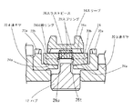
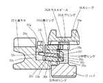
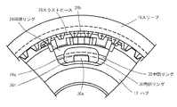
図14、15は、本発明の変速機用同期装置における第3の実施例を表す。
ここでは、実施例1と異なる部分を中心に説明し、実施例1と実質的に同じ部分については同一の符号を付し、それらの説明を省略する。
図14は実施例1の図3に対応する部分拡大断面図であり、図15は同じく図2に対応する部分拡大外観図であって、スプリング28と3速ギヤ20側の同期リング24を取り去って描いてある。
14 and 15 show a third embodiment of the transmission synchronizer of the present invention.
Here, the description will focus on parts that are different from the first embodiment, the same reference numerals are given to parts that are substantially the same as those of the first embodiment, and descriptions thereof are omitted.
14 is a partially enlarged cross-sectional view corresponding to FIG. 3 of the first embodiment, and FIG. 15 is a partially enlarged external view corresponding to FIG. 2 in which the
実施例1と異なるのは、同期リング24の他に内側リング30と中間リング32を有していることである。
すなわち、内側リング30はハブ12側に突起30aを形成して、ハブ12に形成した内側切り欠き12sと回転方向に若干の隙間を有して係合しており、4速ギヤ22の摩擦面22bに対応した内側摩擦面30bと外周に外側摩擦面30cを形成している。
また、中間リング32は突起32aが形成されて4速ギヤ22に形成した窪み22eと回転方向に係合しており、内側リング30の外側摩擦面30cに対応する内側摩擦面32bと、同期リング24の摩擦面24aに対応する外側摩擦面32cとを形成している。
The difference from the first embodiment is that an inner ring 30 and an intermediate ring 32 are provided in addition to the
That is, the inner ring 30 is formed with a
Further, the intermediate ring 32 is engaged with a
したがって、実施例2はいわゆるマルチコーン式の同期装置であり、同期リング24が4速ギヤ22側への押圧力を受けると、摩擦面24aと外側摩擦面32c同士、内側摩擦面32bと外側摩擦面30c同士、内側摩擦面30bと摩擦面22b同士の、3カ所で同時に圧接されて摩擦トルクを生じることになる。
そのため、同期リング24を押圧する力を同じとしても、実施例1より大幅に大きな摩擦トルクを得ることができて、同期能力が大きくなる。
Accordingly, the second embodiment is a so-called multi-cone synchronizer, and when the synchronizing
Therefore, even if the force that presses the
その他の構造および作動は実施例1と同様であり、同期作用終了からスリーブ16が4速ギヤ22と噛み合うまでの間における、両者の相対回転を規制するので、スプライン16aと22a同士の衝突が起きず、操作フィーリングを悪化させることがない。
また、スリーブ16と4速ギヤ22の相対回転を規制するために、余計なスリーブ16の移動がないので、移動距離が大きくなることに起因する操作フィーリングの悪化もない。
Other structures and operations are the same as those in the first embodiment, and the relative rotation of the
Further, since there is no extra movement of the
なお、図示と詳細な説明は省略するが、実施例3に示したマルチコーン式の構成にあっても、実施例2で説明した手段で、スリーブ16と4速ギヤ22の相対回転を規制することができる。
詳細の説明は省略したが、実施例3に示した本発明の変速機用同期装置においても、自己サーボ作用による同期性能の向上を果たしながら、操作フィーリングの悪化を避けることができる。
Although illustration and detailed description are omitted, even in the multi-cone configuration shown in the third embodiment, the relative rotation between the
Although detailed description is omitted, the transmission synchronizer of the present invention shown in the third embodiment can avoid the deterioration of the operation feeling while improving the synchronization performance by the self-servo action.
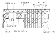
図16、17は、本発明の変速機用同期装置における第4の実施例を表す。
ここでは、実施例1および実施例3と異なる部分を中心に説明し、それらと実質的に同じ部分については同一の符号を付し、それらの説明を省略する。
図16は実施例1の図3に対応する部分拡大断面図であり図14にも対応しており、図17は同じく図2に対応する部分拡大外観図であって図15にも対応しており、図15と同様に、スプリング28と3速ギヤ20側の同期リング24を取り去って描いてある。
16 and 17 show a fourth embodiment of the transmission synchronizer of the present invention.
Here, the description will focus on the parts that are different from the first and third embodiments, the same reference numerals are given to the substantially same parts, and the description thereof is omitted.
16 is a partially enlarged cross-sectional view corresponding to FIG. 3 of the first embodiment, and also corresponds to FIG. 14. FIG. 17 is a partially enlarged external view corresponding to FIG. 2 and also corresponds to FIG. Similarly to FIG. 15, the
実施例4も実施例3と同様にマルチコーン式の同期装置であるが、実施例3と異なるのは、同期リング24と内側リング30とが回転方向に連結されていることである。
すなわち、同期リング24には連結突起24fが設けてあり、これの切り欠き24gが内側リング30の突起30aと係合している。
The fourth embodiment is also a multi-cone synchronizer as in the third embodiment, but differs from the third embodiment in that the
That is, the
このため、同期リング24が4速ギヤ22側への押圧力を受けると、摩擦面24aと外側摩擦面32c同士、内側摩擦面32bと外側摩擦面30c同士、内側摩擦面30bと摩擦面22b同士の、3カ所で同時に圧接されて摩擦トルクを生じることは実施例3と同様である。
For this reason, when the synchronizing
実施例3と異なるのは、これら3カ所の摩擦トルクが全て同期リング24に伝わり、実施例1で説明したように、ハブ12の斜面12g、12h、12i、12jのいずれかに作用して、自己サーボ作用による同期容量の増大を得ることである。
したがって、ハブ12の斜面12g、12h、12i、12jおよび同期リング24のチャンファ24e、24fの傾斜角を適切に設定する必要はあるが、実施例1と同様の作動を行う。
The difference from the third embodiment is that all these three frictional torques are transmitted to the
Therefore, although it is necessary to appropriately set the inclination angles of the
また、同期作用終了からスリーブ16が4速ギヤ22と噛み合うまでの間における、両者の相対回転を規制できるので、スプライン16aと22a同士の衝突が起きず、操作フィーリングを悪化させることがない。
さらに、スリーブ16と4速ギヤ22の相対回転を規制するための、余計なスリーブ16の移動がないので、移動距離が大きくなることに起因する操作フィーリングの悪化もない。
Further, since the relative rotation of the
Further, since there is no extra movement of the
なお、図示と詳細な説明は省略するが、実施例4に示したマルチコーン式の構成にあっても、実施例2で説明した手段で、スリーブ16と4速ギヤ22の相対回転を規制することができる。
詳細の説明は省略したが、実施例4に示した本発明の変速機用同期装置においても、自己サーボ作用による同期性能の向上を果たしながら、操作フィーリングの悪化を避けることができる。
Although illustration and detailed description are omitted, even in the multi-cone configuration shown in the fourth embodiment, the relative rotation between the
Although detailed description is omitted, the transmission synchronizer of the present invention shown in the fourth embodiment can avoid the deterioration of the operation feeling while improving the synchronization performance by the self-servo action.
以上説明したように、本発明の変速機用同期装置は、同期時の摩擦トルクを活用した自己サーボ作用によって同期性能の向上を得ながら、同期作用終了からスリーブ16が4速ギヤ22と噛み合うまでの間における、両者の相対回転を規制するとともに、相対回転を規制するのにスリーブ16の余計な移動がないので、これらに起因する操作フィーリングの悪化を避けることができる。
As described above, the transmission synchronizer according to the present invention obtains the improvement of the synchronization performance by the self-servo action utilizing the friction torque at the time of synchronization, and from the end of the synchronization action until the
このため、手動変速機にあっては操作力の軽減をはかることができて操作性の向上に貢献するとともに、電気モーター等のアクチュエーターによる変速操作を行う変速機にあってはアクチュエーターの容量を小さくすることが可能になり、軽量化や車両の燃費向上に貢献する。 For this reason, the manual transmission can reduce the operating force and contribute to the improvement of the operability. In the transmission that performs a shift operation by an actuator such as an electric motor, the capacity of the actuator is reduced. This contributes to weight reduction and improved vehicle fuel efficiency.
なお、実施例1乃至実施例4は、入力軸10上に同期装置を配置した場合であるが、出力軸側に配置しても同様の作用をすることは言うまでもない。
また、ハブ12の斜面12g、12h、12i、12jと同期リング24のチャンファ24e、24f、およびこれらに対応するスラストピース26のチャンファ26d、26e、26f、26g、スラストチャンファ26j、26k、26l、26mは、傾斜面として説明したが、螺旋面であってもよい。
In addition, although Example 1 thru | or Example 4 is a case where a synchronizer is arrange | positioned on the input shaft 10, it cannot be overemphasized that even if it arrange | positions on the output shaft side, the same effect | action will be carried out.
Further, the
本発明の変速機用同期装置は、当業者の一般的な知識に基づいて、摩擦面における摩擦係数を高めるために同期リングの摩擦面にネジや油溝を形成するなどの変更を加えた態様で実施することができるとともに、摩擦面に適切な材料を用いることによって安定した同期性能の向上を得ることができる。 The transmission synchronization device of the present invention is a mode in which a screw or an oil groove is formed on the friction surface of the synchronization ring to increase the friction coefficient on the friction surface based on general knowledge of those skilled in the art. In addition, it is possible to obtain a stable improvement in synchronization performance by using an appropriate material for the friction surface.
操作フィーリングの悪化を回避しながら同期性能の向上を得ることができるので、特に小型化や製造コストの低減を要求される乗用車用変速機に適用してメリットを得ることができるとともに、アクチュエーターで変速操作を行う変速機などに適用することができる。 Since it is possible to improve synchronization performance while avoiding deterioration in operation feeling, it can be used particularly for passenger car transmissions that are required to be downsized and reduced in manufacturing cost. The present invention can be applied to a transmission that performs a shift operation.
10 入力軸
12 ハブ
14 ブッシュ
16 スリーブ
18 ベアリング
20 3速ギヤ
22 4速ギヤ
24 同期リング
26 スラストピース
28 スプリング
30 内側リング
32 中間リング
DESCRIPTION OF SYMBOLS 10
Claims (5)
該軸に固定されるボス部から径方向外側に延ばしたフランジ部の外周に複数の切り欠きとスプラインとを形成するとともに、前記切り欠きに回転方向の力を軸方向の力に転換可能な斜面を形成したハブと、
内周にスプラインと該スプラインの内側に溝とが形成され、前記ハブの前記スプラインに軸方向摺動可能に支持されたスリーブと、
該スリーブが嵌合可能なスプラインおよび摩擦面が前記ハブ側に一体的に設けられた変速ギヤと、
該変速ギヤの前記摩擦面に圧接可能な摩擦面が形成され、外周にチャンファを有する突起が設けられた同期リングと、
前記スリーブの溝に挿入され、該スリーブから軸方向に押圧されて、前記同期リングの前記チャンファを押圧する過程で該同期リングに生ずる摩擦トルクを前記ハブの前記斜面に伝えるスラストピースと、
前記スラストピースが前記同期リングを軸方向に押圧して行う同期作用が終了した後に、前記同期リングと前記ハブの間における相対回転を規制する規制手段とを備えたことを特徴とする変速機用同期装置。 A shaft that transmits power,
A slope having a plurality of notches and splines formed on the outer periphery of a flange portion extending radially outward from a boss portion fixed to the shaft and capable of converting rotational force into axial force in the notches With the hub formed,
A sleeve formed with a spline on the inner periphery and a groove inside the spline, and supported by the spline of the hub so as to be axially slidable;
A transmission gear in which a spline and a friction surface to which the sleeve can be fitted are integrally provided on the hub side;
A synchronous ring in which a friction surface capable of being pressed against the friction surface of the transmission gear is formed, and a protrusion having a chamfer is provided on the outer periphery;
A thrust piece that is inserted into the groove of the sleeve, is axially pressed from the sleeve, and transmits a friction torque generated in the synchronization ring to the inclined surface of the hub in a process of pressing the chamfer of the synchronization ring;
For a transmission, comprising: a regulating means for regulating relative rotation between the synchronizing ring and the hub after the synchronizing action performed by the thrust piece pressing the synchronizing ring in the axial direction is completed. Synchronizer.
前記スラストピースに形成したガイド爪とを有し、該ガイド爪が、前記ハブの前記ガイドスプラインと当接または係合することにより、前記同期リングと前記ハブとの相対回転を規制するようにしたことを特徴とする請求項1に記載の変速機用同期装置。 The restricting means includes a guide spline formed on the hub;
A guide claw formed on the thrust piece, and the guide claw abuts or engages with the guide spline of the hub, thereby restricting relative rotation between the synchronization ring and the hub. The transmission synchronizer according to claim 1.
前記スリーブに形成したガイドスプラインとを有し、該ガイドスプラインが、前記同期リングの前記スプラインと係合することにより、前記同期リングと前記ハブとの相対回転を規制するようにしたことを特徴とする請求項1に記載の変速機用同期装置。 The regulating means includes a spline formed on the synchronization ring,
A guide spline formed on the sleeve, and the guide spline engages with the spline of the synchronization ring to restrict relative rotation between the synchronization ring and the hub. The transmission synchronizer according to claim 1.
5. The transmission for a transmission according to claim 1, wherein an inner surface chamfer is formed on a radially inner side of the thrust piece, and an annular spring is disposed between the inner surface chamfer and the synchronization ring. Synchronizer.
Priority Applications (2)
| Application Number | Priority Date | Filing Date | Title |
|---|---|---|---|
| JP2004109562A JP2005291423A (en) | 2004-04-02 | 2004-04-02 | Synchronizing device for transmission |
| PCT/JP2005/006889 WO2005095814A1 (en) | 2004-04-02 | 2005-04-01 | Synchronization device for transmission |
Applications Claiming Priority (1)
| Application Number | Priority Date | Filing Date | Title |
|---|---|---|---|
| JP2004109562A JP2005291423A (en) | 2004-04-02 | 2004-04-02 | Synchronizing device for transmission |
Publications (1)
| Publication Number | Publication Date |
|---|---|
| JP2005291423A true JP2005291423A (en) | 2005-10-20 |
Family
ID=35063850
Family Applications (1)
| Application Number | Title | Priority Date | Filing Date |
|---|---|---|---|
| JP2004109562A Pending JP2005291423A (en) | 2004-04-02 | 2004-04-02 | Synchronizing device for transmission |
Country Status (2)
| Country | Link |
|---|---|
| JP (1) | JP2005291423A (en) |
| WO (1) | WO2005095814A1 (en) |
Cited By (2)
| Publication number | Priority date | Publication date | Assignee | Title |
|---|---|---|---|---|
| AT506205B1 (en) * | 2007-12-18 | 2011-11-15 | Miba Sinter Austria Gmbh | POWER GAIN ELEMENT |
| JP2013040652A (en) * | 2011-08-17 | 2013-02-28 | O-Oka Corp | Synchronous clutch gear for double-cone synchronization |
Families Citing this family (3)
| Publication number | Priority date | Publication date | Assignee | Title |
|---|---|---|---|---|
| JP4609796B2 (en) * | 2005-08-05 | 2011-01-12 | 協和合金株式会社 | Synchronizer for transmission |
| KR101341384B1 (en) * | 2009-09-14 | 2013-12-13 | 호르비거 안트립스테크닉 홀딩 게엠베하 | Assembly unit comprising two synchroniser rings |
| DE102016223002B3 (en) | 2016-11-22 | 2018-03-01 | GETRAG B.V. & Co. KG | Servo-synchronization device for a transmission of a motor vehicle |
Family Cites Families (4)
| Publication number | Priority date | Publication date | Assignee | Title |
|---|---|---|---|---|
| US2555961A (en) * | 1946-11-27 | 1951-06-05 | Chrysler Corp | Transmission synchromesh mechanism |
| DE3622464C1 (en) * | 1986-07-04 | 1987-12-17 | Getrag Getriebe- Und Zahnradfabrik Gmbh, 7140 Ludwigsburg, De | |
| DE4324814A1 (en) * | 1993-07-23 | 1995-01-26 | Zahnradfabrik Friedrichshafen | Gear shift with lock synchronization |
| US5588516A (en) * | 1993-12-27 | 1996-12-31 | Eaton Corporation | Synchronizer with self-energizing |
-
2004
- 2004-04-02 JP JP2004109562A patent/JP2005291423A/en active Pending
-
2005
- 2005-04-01 WO PCT/JP2005/006889 patent/WO2005095814A1/en not_active Ceased
Cited By (3)
| Publication number | Priority date | Publication date | Assignee | Title |
|---|---|---|---|---|
| AT506205B1 (en) * | 2007-12-18 | 2011-11-15 | Miba Sinter Austria Gmbh | POWER GAIN ELEMENT |
| US8733523B2 (en) | 2007-12-18 | 2014-05-27 | Miba Sinter Austria Gmbh | Power assist element |
| JP2013040652A (en) * | 2011-08-17 | 2013-02-28 | O-Oka Corp | Synchronous clutch gear for double-cone synchronization |
Also Published As
| Publication number | Publication date |
|---|---|
| WO2005095814A1 (en) | 2005-10-13 |
Similar Documents
| Publication | Publication Date | Title |
|---|---|---|
| JP4716114B2 (en) | Synchronizer for transmission | |
| JP4609796B2 (en) | Synchronizer for transmission | |
| JP6218356B2 (en) | Synchronizer for transmission | |
| US20050061095A1 (en) | Automotive power transmission with synchromesh mechanism | |
| WO2002046633A1 (en) | Synchronizer for speed reducer | |
| JP6183999B2 (en) | Synchronizer for transmission | |
| JP5020903B2 (en) | Power transmission device | |
| JP2005291423A (en) | Synchronizing device for transmission | |
| JP2012057786A (en) | Synchronous joining mechanism of transmission | |
| JP2008215600A (en) | Synchromesh device of manual transmission | |
| EP2677189A1 (en) | Gearbox for a vehicle and a vehicle including such a gearbox | |
| JP4246606B2 (en) | Transmission synchronization mechanism | |
| JP2006226515A (en) | Synchronizing device for transmission | |
| JP2009236202A (en) | Synchronizing device for transmission | |
| JP2007285400A (en) | Synchronizing device for transmission | |
| JP2005113975A (en) | Synchronizing device for transmission | |
| JP2006226516A (en) | Synchronizing device for transmission | |
| JP2008032072A (en) | Gearbox synchronizer | |
| JP6204156B2 (en) | Synchronizer for transmission | |
| JP2009036217A (en) | Gearbox synchronizer | |
| JP2008215450A (en) | Gearbox synchronizer | |
| JP2907645B2 (en) | Transmission structure | |
| WO2019151261A1 (en) | Clutch unit | |
| JP2011190899A (en) | Synchronizing device for transmission | |
| JPH10246246A (en) | Synchronizer for transmission |