JP2005291404A - Multi-purpose fastener - Google Patents
Multi-purpose fastener Download PDFInfo
- Publication number
- JP2005291404A JP2005291404A JP2004108463A JP2004108463A JP2005291404A JP 2005291404 A JP2005291404 A JP 2005291404A JP 2004108463 A JP2004108463 A JP 2004108463A JP 2004108463 A JP2004108463 A JP 2004108463A JP 2005291404 A JP2005291404 A JP 2005291404A
- Authority
- JP
- Japan
- Prior art keywords
- hole
- base
- insertion hole
- suction cup
- center
- Prior art date
- Legal status (The legal status is an assumption and is not a legal conclusion. Google has not performed a legal analysis and makes no representation as to the accuracy of the status listed.)
- Ceased
Links
- 238000003780 insertion Methods 0.000 claims abstract description 39
- 230000037431 insertion Effects 0.000 claims abstract description 39
- 238000000034 method Methods 0.000 description 8
- 230000006835 compression Effects 0.000 description 4
- 238000007906 compression Methods 0.000 description 4
- 230000005484 gravity Effects 0.000 description 3
- CWYNVVGOOAEACU-UHFFFAOYSA-N Fe2+ Chemical compound [Fe+2] CWYNVVGOOAEACU-UHFFFAOYSA-N 0.000 description 2
- 230000008878 coupling Effects 0.000 description 2
- 238000010168 coupling process Methods 0.000 description 2
- 238000005859 coupling reaction Methods 0.000 description 2
- 230000000694 effects Effects 0.000 description 1
- 239000011521 glass Substances 0.000 description 1
- 239000002184 metal Substances 0.000 description 1
- 238000012986 modification Methods 0.000 description 1
- 230000004048 modification Effects 0.000 description 1
- 238000001179 sorption measurement Methods 0.000 description 1
Images


Landscapes
- Clamps And Clips (AREA)
- Hooks, Suction Cups, And Attachment By Adhesive Means (AREA)
Abstract
Description
この発明は、物品を机などに可動な状態で支持する固定具に関する。 The present invention relates to a fixture that supports an article in a movable state on a desk or the like.
事務用の机に設けられ、一般に照明用の電気スタンド、テープホルダ、パーソナル・ディジタルアシストの支持具、小型の扇風機、マイクロフォン、センサ装置、メモ挟み、ネットワーク用カメラなどを支持する従来の可動式固定具は、重力式、挟持式、もしくはマグネット式などが主に挙げられる。重力式は、固定具自体の重量を利用して支持する物体を固定し安定させる。しかし、かかる固定方式は、強制的固定力に欠けるため重心が容易に不安定となるか、不注意でぶつかるなど外部からの力を受けると容易に転倒する。挟持式は、挟持部が付設されていて、該挟持具によって机の天板の端縁部か、もしくはその他挟持できる場所を挟持して物体を固定させる目的を達成する。かかる固定方式は、机の天板の端縁部か、もしくはその他挟持できる場所にしか用いることができない。よって、場所を選ばす用いることができず不便である、マグネット式は、固定具に磁石を設けてなり、鉄質の物体に吸着させて物体を固定する目的を達成する。かかる固定方式は、非鉄製の机には用いることができず、コストも高くなることが欠点として挙げられる。 Conventional movable fixed fixtures that are installed on office desks and generally support desk lamps for lighting, tape holders, personal digital assist supports, small fans, microphones, sensor devices, note clamps, network cameras, etc. Examples of the tool mainly include a gravity type, a clamping type, and a magnet type. The gravity type uses the weight of the fixture itself to fix and stabilize the object to be supported. However, such a fixing method lacks a compulsory fixing force, so that the center of gravity easily becomes unstable or falls easily when it receives an external force such as inadvertent collision. The sandwiching type is provided with a sandwiching portion, and achieves the object of fixing an object by sandwiching the edge of the top plate of the desk or other place where it can be sandwiched by the sandwiching tool. Such a fixing method can be used only at the edge of the top of the desk or at other places where it can be sandwiched. Therefore, the magnet type, which is inconvenient because it cannot be used by selecting a place, is provided with a magnet in a fixing tool, and achieves the object of fixing the object by attracting it to a ferrous object. Such a fixing method cannot be used for a non-ferrous desk, and the cost is high.
この発明の課題は、安定した固定が得られ、ぶつかったり、振動を受けたりして外部からの力を受けても緩んだり、転倒したりすることのない多目的固定具を提供することにある。 An object of the present invention is to provide a multipurpose fixing tool that can be stably fixed and does not loosen or fall over even if it is bumped or vibrated and receives external force.
また、この発明の課題は、固定する箇所を傷つけることなく、かつ使用する場所に応じて適宜な固定方式を選択できる多目的固定具を提供することにある。 Moreover, the subject of this invention is providing the multipurpose fixing tool which can select an appropriate fixing system according to the place to be used, without damaging the location to fix.
請求項1に記載する多目的固定具は、ベースと、吸盤と、制動グリップと、弾性部材と、挟持部と、締結部材とを含んでなり、
該吸盤は該ベースを構成する円盤体の底面側に位置し、かつ該吸盤の上面中央には該ベースを貫通して該制動グリップを上端に回動自在に設ける軸桿を形成し、該制動グリップの作用で上下に移動するように構成し、
該ベースは円盤体の円周上の一側面から延伸して形成される連結具を具え、該円盤体上面の中央の位置に平面部を形成し、該平面部の中央に貫通孔を穿設してなり、別途、該連結具の上面に円形の連結孔と矩形の挿入孔を穿設し、かつ側面から水平方向の固定孔を形成し、
該弾性部材は該ベースの平面部と該制動グリップとの間に設けられ、中心部にプレス加工で突起した弾性体を形成し、該弾性体内には挿通孔を穿設してなり、
該挟持部は、L字状の支持フレームの垂直部上端に挿入部を一体に形成し、該挿入部を該ベースの挿入孔に挿入し、該締結部材を螺合させてベースを固定し、
該連結具の連結孔に支持する物品の支持桿を挿入して固定し、該吸盤で所定の位置に吸着させて固定するか、もしく該挟持部で所定の位置を挟持して固定できるように構成してなるものである。
The multipurpose fixture according to
The suction cup is positioned on the bottom surface side of the disc body constituting the base, and a shaft rod is formed in the center of the upper surface of the suction cup so as to pass through the base and rotate the braking grip at the upper end. Configure to move up and down by the action of the grip,
The base includes a connecting member formed by extending from one side of the circumference of the disc body, and forms a flat portion at the center position of the upper surface of the disc body, and a through hole is formed in the center of the flat portion. In addition, a circular connecting hole and a rectangular insertion hole are drilled on the upper surface of the connecting tool, and a horizontal fixing hole is formed from the side surface.
The elastic member is provided between the flat portion of the base and the braking grip, and forms an elastic body protruding by pressing at the center, and an insertion hole is formed in the elastic body.
The sandwiching portion integrally forms an insertion portion at the upper end of the vertical portion of the L-shaped support frame, inserts the insertion portion into the insertion hole of the base, and screws the fastening member to fix the base,
The support rod of the article to be supported is inserted and fixed in the connection hole of the connector, and can be fixed by being sucked and fixed at a predetermined position by the suction cup, or can be fixed by holding the predetermined position by the holding portion. It is constituted by.
請求項2に記載する多目的固定具は、請求項1における挟持部のL字状支持フレームの水平部に、上端に当接円盤を設け、下端縁に貫通孔を形成した圧迫ボルトを設けたものである。
The multipurpose fixture according to claim 2 is provided with a compression bolt having a contact disk at the upper end and a through hole formed at the lower end edge in the horizontal portion of the L-shaped support frame of the clamping portion in
請求項3に記載する多目的固定具は、請求項1におけるベースの連結具に形成する挿入孔に、該挿入孔の形状に対応して形成され、ほぼ中央に位置にネジ孔を形成してなる挿入部材を挿入して構成したものである。
The multipurpose fixing tool described in claim 3 is formed in the insertion hole formed in the base coupling tool in
本発明に係る多目的固定具は、着脱が便利で、使用する机の天板などを傷つけることがない。また、安定した固定が得られ、ぶつかったり、振動を受けたりして外部の力を受けても、緩んだり、転倒したりすることがなく、さらに取りつける場所によって挟持する方式か、吸盤で吸着させる方式か、もしくはその他の方法を選択することができるという利点がある。 The multipurpose fixture according to the present invention is convenient to attach and detach, and does not damage the top plate of the desk to be used. In addition, stable fixation is obtained, and even if it is bumped or subjected to external force due to vibration, it does not loosen or fall over, and it is further clamped by the place where it is attached or sucked with a suction cup There is an advantage that a method or other methods can be selected.
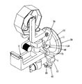
図1から4に、この発明に係る多目的固定具を開示する。図面によれば、この発明の多目的固定具は、ベース(10)と、制動グリップ(30)と、弾性部材(40)と、挟持部(50)と、締結部材(60)とを含んでなる。ベース(10)は、円盤体(11)の円周上の一側面から延伸して形成される連結座(12)を具え、該円盤体(11)上面の中央の位置に平面部(111)を形成し、該平面部(111)の中央に貫通孔(112)を穿設する。別途、連結座(12)の上面に円形の連結孔(121)と矩形の挿入孔(122)を穿設し、かつ側面から水平方向の固定孔(123)を形成する。該固定孔(123)は連結孔(121)と挿入孔(122)とに連通する。また、吸盤(20)を円盤体(11)に設ける。吸盤(20)は上面に断面が矩形を呈する軸桿(21)を具え、かつ該軸桿(21)の上端に支持孔(211)を形成する。 1 to 4 disclose a multipurpose fixture according to the present invention. According to the drawings, the multipurpose fixture of the present invention comprises a base (10), a braking grip (30), an elastic member (40), a clamping part (50), and a fastening member (60). . The base (10) includes a coupling seat (12) formed by extending from one side of the circumference of the disc body (11), and the flat surface portion (111) at the center position of the upper surface of the disc body (11). And a through hole (112) is formed in the center of the flat portion (111). Separately, a circular connection hole (121) and a rectangular insertion hole (122) are formed on the upper surface of the connection seat (12), and a horizontal fixing hole (123) is formed from the side surface. The fixing hole (123) communicates with the connection hole (121) and the insertion hole (122). Moreover, a suction cup (20) is provided in a disk body (11). The suction cup (20) has a shaft rod (21) having a rectangular cross section on the upper surface, and a support hole (211) is formed at the upper end of the shaft rod (21).
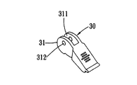
制動グリップ部(30)は、一端に押圧部(31)を形成し、該押圧部(31)内に溝(311)を形成する。別途、押圧部(31)の側面の偏心した位置には、水平方向に該溝(311)を貫通する軸支孔(312)
を形成する(図3、4参照)。
The brake grip part (30) forms a pressing part (31) at one end, and forms a groove (311) in the pressing part (31). Separately, a shaft support hole (312) that penetrates the groove (311) in the horizontal direction is provided at an eccentric position on the side surface of the pressing portion (31).
(See FIGS. 3 and 4).
弾性部材(40)は中心部にプレス加工で突起した弾性体(41)を形成する。弾性体(41)内には、吸盤(20)の軸桿(21)の断面の形状に対応する挿通孔(411)を穿設する。 The elastic member (40) forms an elastic body (41) protruding at the center by press working. An insertion hole (411) corresponding to the cross-sectional shape of the shaft rod (21) of the suction cup (20) is formed in the elastic body (41).
挟持部(50)は、L字状の支持フレーム(51)の水平部には、上端に当接円盤(521)を設け、下端縁に貫通孔(522)を形成した圧迫ボルト(52)を設ける。また、垂直部には上端にベース(10)の挿入孔(122)に形状が対応する挿入部(511)を一体に形成し、該挿入部(511)の略中間の位置にネジ孔(512)を穿設する。 The clamping part (50) is provided with a compression bolt (52) provided with a contact disk (521) at the upper end and a through hole (522) at the lower edge at the horizontal part of the L-shaped support frame (51). Provide. In addition, an insertion portion (511) whose shape corresponds to the insertion hole (122) of the base (10) is integrally formed at the upper end of the vertical portion, and a screw hole (512) is formed at a substantially middle position of the insertion portion (511). ).
以上の部材を組み立てる場合、弾性部材(40)を円盤体(11)上面の貫通孔(112)上に設置し、下方から吸盤(20)の軸桿(21)を円盤体(11)の貫通孔(112)と弾性部材(40)の挿通孔(312)に挿通させ、吸盤(20)を円盤体(11)の底面に位置させる。次いで、制動グリップ(30)の溝(311)に吸盤(20)の軸桿(21)の上端縁部を嵌挿し、支軸ピン(70)を制動グリップ(30)の軸支孔(312)と軸桿(21)の支持孔(211)に挿入し、軸桿(21)を制動グリップ(30)に回動自在に支持する(図6参照)。 When assembling the above members, the elastic member (40) is installed on the through hole (112) on the upper surface of the disc body (11), and the shaft rod (21) of the suction cup (20) is penetrated through the disc body (11) from below. The suction hole (112) is inserted into the insertion hole (312) of the elastic member (40), and the suction cup (20) is positioned on the bottom surface of the disk body (11). Next, the upper end edge of the shaft rod (21) of the suction cup (20) is fitted into the groove (311) of the brake grip (30), and the support pin (70) is inserted into the shaft support hole (312) of the brake grip (30). And the shaft rod (21) is inserted into the support hole (211), and the shaft rod (21) is rotatably supported by the brake grip (30) (see FIG. 6).
また、挟持部(50)の挿入部(511)を下方からベース(10)の連結座(12)に形成した挿入孔(121)に挿入し、締結部材(60)を連結座(12)の固定孔(123)と該挿入孔(121)に螺合させて固定することによって組立てが完成する。 Moreover, the insertion part (511) of the clamping part (50) is inserted into the insertion hole (121) formed in the connection seat (12) of the base (10) from below, and the fastening member (60) is inserted into the connection seat (12). The assembly is completed by screwing and fixing the fixing hole (123) and the insertion hole (121).
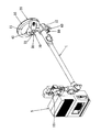
図5に、この発明による多目的固定具の使用態様を開示する。この発明の多目的固定具を使用する場合は、締結部材(60)を緩め、折り畳み自在に構成された支持桿(1)を連結座(12)の連結孔(121)内に挿入する。該支持桿(1)の上端には照明具である電気スタンド(2)、テープホルダ、PDA支持具、小型の扇風機、マイクロフォン、センサ装置、メモ挟み、もしくはネットワーク用カメラなどの物品を直接固定するか、もしくは着脱自在に設けることができる。次いで、締結部材(60)を締めて、その一端を該支持桿(1)の下方に形成された環状の溝に当接させて圧迫し、安定した固定を得る。さらに、吸盤(20)を机の天板に吸着させ、制動グリップ(30)を操作し、押圧部(30)で弾性部材(40)の弾性体(41)を押し圧し、弾性部材(40)の付勢力で吸盤(20)を圧迫し、かつ吸盤(20)の軸桿(21)を上方に引き上げて吸盤(20)を変形させ、その中央を突起させて強力な吸着力を発生させて、机の天板の所定の位置に吸着させる。この場合、挟持部(50)の圧迫ボルト(52)を回転させて上方に向かって移動させ、上端の当接円盤(521)を圧迫して机の天板の底面側に当接させる。以上の操作によってこの発明の多目的固定具の取り付けが完了する。 FIG. 5 discloses a mode of use of the multipurpose fixture according to the present invention. When using the multipurpose fixture of the present invention, the fastening member (60) is loosened, and the support rod (1) configured to be foldable is inserted into the connection hole (121) of the connection seat (12). An article such as a table lamp (2), a tape holder, a PDA support, a small electric fan, a microphone, a sensor device, a nip clip, or a network camera is directly fixed to the upper end of the support rod (1). Or it can be detachably provided. Next, the fastening member (60) is tightened, and one end of the fastening member (60) is brought into contact with an annular groove formed below the support rod (1) and pressed to obtain stable fixation. Further, the suction cup (20) is adsorbed to the top plate of the desk, the brake grip (30) is operated, and the elastic body (41) of the elastic member (40) is pressed and pressed by the pressing portion (30), and the elastic member (40). The suction cup (20) is squeezed by the urging force and the shaft rod (21) of the suction cup (20) is pulled upward to deform the suction cup (20), and the center is projected to generate a strong suction force. Then, it is adsorbed to a predetermined position on the top plate of the desk. In this case, the compression bolt (52) of the clamping part (50) is rotated and moved upward, and the contact disk (521) at the upper end is compressed and brought into contact with the bottom surface side of the top plate of the desk. With the above operation, the attachment of the multipurpose fixture of the present invention is completed.
また、机の上面、もしくは壁面が適宜な平坦性を有する場合(例えばガラス面、金属面など)、挟持部(50)を取り外し、別途図6に開示するように挿入部材(80)をベース(10)の挿入孔(122)に挿入してもよい。該挿入部材(80)は、該挿入孔(122)の形状に対応して形成され、ほぼ中央の位置にネジ孔(811)を形成する。この場合、図7に開示するテープホルダ(3)、図8に開示するPDAなどの支持具(4)、もしくは図9に開示するように支持具(101)で支持したセンサ装置(5)などの支持桿(1)をベース(10)の連結座(12)に形成した連結孔(121)に挿入し、締結部材(60)を連結座(12)の固定孔(123)と該挿入部材(80)の挿入孔(122)に螺合させ、支持桿(1)の環状溝に当止させて固定する。また、吸盤(20)は直接の強力な吸着力で机の天板、もしくは壁面に吸着させる。 Further, when the upper surface or wall surface of the desk has appropriate flatness (for example, a glass surface, a metal surface, etc.), the clamping portion (50) is removed, and the insertion member (80) is used as a base (as disclosed in FIG. 6). You may insert in the insertion hole (122) of 10). The insertion member (80) is formed corresponding to the shape of the insertion hole (122), and forms a screw hole (811) at a substantially central position. In this case, a tape holder (3) disclosed in FIG. 7, a support tool (4) such as a PDA disclosed in FIG. 8, or a sensor device (5) supported by the support tool (101) as disclosed in FIG. The support rod (1) is inserted into the connection hole (121) formed in the connection seat (12) of the base (10), and the fastening member (60) is inserted into the fixing hole (123) of the connection seat (12) and the insertion member. It is screwed into the insertion hole (122) of (80) and is fixed to the annular groove of the support rod (1). Further, the suction cup (20) is adsorbed on the top plate or wall surface of the desk with a direct strong adsorption force.
さらに、該挿入部材(80)には、例えばフック部を一体に形成してなる掛止部材(図示しない)を設けるように構成してもよい。この場合、この発明の多目的固定具を取りつける方法の選択肢がさらに広がる。 Further, the insertion member (80) may be configured to be provided with a hooking member (not shown) formed by integrally forming a hook portion, for example. In this case, the options of the method for attaching the multipurpose fixture of the present invention are further expanded.
この発明による多目的固定具は、着脱が便利であり、かつ使用する机の天板などを傷つけることがない。また、安定した固定が得られ、ぶつかったり、振動を受けたりして外部の力を受けても、緩んだり、転倒したりすることがない。 The multipurpose fixture according to the present invention is convenient to attach and detach, and does not damage the top plate of the desk to be used. In addition, stable fixation is obtained, and even if it is bumped or subjected to external force due to vibration, it does not loosen or fall over.
また、図7に開示するようなテープの台の固定、図8に開示するようなPDFの支持具など多目的に利用できるのみならず、取りつける場所によって挟持する方式か、吸盤で吸着させる方式か選択することができる。 In addition to fixing the tape base as disclosed in FIG. 7 and the PDF support as disclosed in FIG. 8, it can be used for various purposes, as well as the method of holding by the place of attachment or the method of adsorbing with a suction cup can do.
以上はこの発明の好ましい実施例であって、この発明の実施の範囲を限定するものではない。よって、当業者のなし得る修正、もしくは変更であって、この発明の精神の下においてなされ、この発明に対して均等の効果を有するものは、いずれも本発明の特許請求の範囲に属するものとする。 The above are preferred embodiments of the present invention, and do not limit the scope of the present invention. Therefore, any modifications or changes that can be made by those skilled in the art, which are made within the spirit of the present invention and have an equivalent effect on the present invention, shall belong to the scope of the claims of the present invention. To do.
1 支持桿
10 ベース
101 支持具
11 円盤体
111 平面部
112 貫通孔
12 連結座
121 連結孔
122 挿入孔
123 固定孔
2 電気スタンド
20 吸盤
21 軸桿
211 支持孔
3 テープホルダ
30 制動グリップ
31 押圧部
311 溝
312 軸支孔
4 支持具
40 弾性部材
41 弾性体
411 挿通孔
412 ネジ孔
5 センサ装置
50 挟持部
51 支持フレーム
511 挿入部
52 圧迫ボルト
521 当接円盤
522 貫通孔
60 締結部材
70 支軸ピン
80 挿入部材
DESCRIPTION OF
Claims (3)
該吸盤は該ベースを構成する円盤体の底面側に位置し、かつ該吸盤の上面中央には該ベースを貫通して該制動グリップを上端に回動自在に設ける軸桿を形成し、該制動グリップの作用で上下に移動するように構成し、
該ベースは円盤体の円周上の一側面から延伸して形成される連結座を具え、該円盤体上面の中央の位置に平面部を形成し、該平面部の中央に貫通孔を穿設してなり、別途、該連結座の上面に円形の連結孔と矩形の挿入孔を穿設し、かつ側面から水平方向の固定孔を形成し、
該弾性部材は該ベースの平面部と該制動グリップとの間に設けられ、中心部にプレス加工で突起した弾性体を形成し、該弾性体内には挿通孔を穿設してなり、
該挟持部は、L字状の支持フレームの垂直部上端に挿入部を一体に形成し、該挿入部を該ベースの挿入孔に挿入し、該締結部材を螺合させてベースを固定し、
該連結座の連結孔に支持する物品の支持桿を挿入して固定し、該吸盤で所定の位置に吸着させて固定するか、もしく該挟持部で所定の位置を挟持して固定できるように構成することを特徴とする多目的固定具。 A base, a suction cup, a braking grip, an elastic member, a clamping part, and a fastening member;
The suction cup is positioned on the bottom surface side of the disc body constituting the base, and a shaft rod is formed in the center of the upper surface of the suction cup so as to pass through the base and rotate the braking grip at the upper end. Configure to move up and down by the action of the grip,
The base includes a connecting seat formed by extending from one side of the circumference of the disk body, and forms a flat portion at the center position of the upper surface of the disk body, and a through hole is formed in the center of the flat portion. Separately, a circular connecting hole and a rectangular insertion hole are drilled on the upper surface of the connecting seat, and a horizontal fixing hole is formed from the side surface,
The elastic member is provided between the flat portion of the base and the braking grip, and forms an elastic body protruding by pressing at the center, and an insertion hole is formed in the elastic body.
The sandwiching portion integrally forms an insertion portion at the upper end of the vertical portion of the L-shaped support frame, inserts the insertion portion into the insertion hole of the base, and screws the fastening member to fix the base,
The support rod of the article to be supported is inserted and fixed in the connection hole of the connection seat, and is fixed by being sucked to the predetermined position by the suction cup, or by holding the predetermined position by the holding portion. A multi-purpose fixing device characterized by comprising:
Priority Applications (1)
| Application Number | Priority Date | Filing Date | Title |
|---|---|---|---|
| JP2004108463A JP2005291404A (en) | 2004-03-31 | 2004-03-31 | Multi-purpose fastener |
Applications Claiming Priority (1)
| Application Number | Priority Date | Filing Date | Title |
|---|---|---|---|
| JP2004108463A JP2005291404A (en) | 2004-03-31 | 2004-03-31 | Multi-purpose fastener |
Publications (1)
| Publication Number | Publication Date |
|---|---|
| JP2005291404A true JP2005291404A (en) | 2005-10-20 |
Family
ID=35324556
Family Applications (1)
| Application Number | Title | Priority Date | Filing Date |
|---|---|---|---|
| JP2004108463A Ceased JP2005291404A (en) | 2004-03-31 | 2004-03-31 | Multi-purpose fastener |
Country Status (1)
| Country | Link |
|---|---|
| JP (1) | JP2005291404A (en) |
Cited By (10)
| Publication number | Priority date | Publication date | Assignee | Title |
|---|---|---|---|---|
| WO2008064531A1 (en) * | 2006-11-28 | 2008-06-05 | Quan Zhou | A signal receiver bracket of gps |
| CN102261550A (en) * | 2011-07-08 | 2011-11-30 | 迈柯唯医疗设备(苏州)有限公司 | Multi-purpose connector |
| CN103775474A (en) * | 2012-10-19 | 2014-05-07 | 纬创资通股份有限公司 | Electronic device and fixing module thereof |
| CN103836054A (en) * | 2012-11-20 | 2014-06-04 | 昆山研达电脑科技有限公司 | Sucker prevented from falling off |
| CN105715923A (en) * | 2016-03-23 | 2016-06-29 | 赵静 | Installation frame for box-type sensor |
| CN106224717A (en) * | 2016-09-23 | 2016-12-14 | 苏州盛开信息科技有限公司 | A kind of Novel rotary fixing camera fixes seat |
| CN107842548A (en) * | 2017-11-17 | 2018-03-27 | 宁波凯波智能熨烫电器制造有限公司 | A hanger hook with multiple fixing methods |
| CN108332015A (en) * | 2018-01-24 | 2018-07-27 | 康佳集团股份有限公司 | A kind of television set hanging set and television set wall hanging monitoring method |
| CN111550662A (en) * | 2020-05-12 | 2020-08-18 | 杜明亮 | Smart city security monitoring equipment based on big data |
| CN117346046A (en) * | 2023-12-06 | 2024-01-05 | 滨州泽郦精密金属科技有限公司 | A quick-installed flame detector for offshore platforms |
-
2004
- 2004-03-31 JP JP2004108463A patent/JP2005291404A/en not_active Ceased
Cited By (11)
| Publication number | Priority date | Publication date | Assignee | Title |
|---|---|---|---|---|
| WO2008064531A1 (en) * | 2006-11-28 | 2008-06-05 | Quan Zhou | A signal receiver bracket of gps |
| CN102261550A (en) * | 2011-07-08 | 2011-11-30 | 迈柯唯医疗设备(苏州)有限公司 | Multi-purpose connector |
| CN103775474A (en) * | 2012-10-19 | 2014-05-07 | 纬创资通股份有限公司 | Electronic device and fixing module thereof |
| CN103836054A (en) * | 2012-11-20 | 2014-06-04 | 昆山研达电脑科技有限公司 | Sucker prevented from falling off |
| CN105715923A (en) * | 2016-03-23 | 2016-06-29 | 赵静 | Installation frame for box-type sensor |
| CN106224717A (en) * | 2016-09-23 | 2016-12-14 | 苏州盛开信息科技有限公司 | A kind of Novel rotary fixing camera fixes seat |
| CN107842548A (en) * | 2017-11-17 | 2018-03-27 | 宁波凯波智能熨烫电器制造有限公司 | A hanger hook with multiple fixing methods |
| CN108332015A (en) * | 2018-01-24 | 2018-07-27 | 康佳集团股份有限公司 | A kind of television set hanging set and television set wall hanging monitoring method |
| CN111550662A (en) * | 2020-05-12 | 2020-08-18 | 杜明亮 | Smart city security monitoring equipment based on big data |
| CN117346046A (en) * | 2023-12-06 | 2024-01-05 | 滨州泽郦精密金属科技有限公司 | A quick-installed flame detector for offshore platforms |
| CN117346046B (en) * | 2023-12-06 | 2024-03-26 | 滨州泽郦精密金属科技有限公司 | A fast-assembling formula flame detector for platform |
Similar Documents
| Publication | Publication Date | Title |
|---|---|---|
| US6962314B2 (en) | Multifunctional holder | |
| US20050236540A1 (en) | Loudspeaker wall bracket | |
| JP2005291404A (en) | Multi-purpose fastener | |
| CN204187219U (en) | Quick-release assembly of mobile device bracket | |
| CN215489311U (en) | Fixing frame and auxiliary device applying same | |
| US9109746B1 (en) | Mounting apparatus for a portable electronic device | |
| TWI489872B (en) | monitor | |
| CN2660284Y (en) | Multi-function holder | |
| US6299117B1 (en) | Clamping device | |
| US4984135A (en) | Interchangeable camera light mount | |
| JPH0747023Y2 (en) | Wireless switch mounting structure | |
| CN204114865U (en) | A seating clip double-purpose desk lamp | |
| CN221402874U (en) | Removable lamps | |
| JP2006209043A (en) | Thin type television device | |
| CN222634184U (en) | A quick-install camera base | |
| CN223537287U (en) | tripod and gimbal | |
| CN206530970U (en) | A conveniently installed car lamp bracket | |
| CN212657483U (en) | Network camera fixing piece | |
| JP2532062Y2 (en) | Battery mounting device | |
| CN223194746U (en) | Electronic equipment bracket with waterproof box | |
| JP2006055487A (en) | Holding device for bar-shaped article | |
| JP2541021Y2 (en) | Clamp hanger | |
| CN207059924U (en) | A suction cup bracket | |
| CN210609308U (en) | Miniature cell-phone projecting apparatus support | |
| JP2002250309A (en) | Fixture |
Legal Events
| Date | Code | Title | Description |
|---|---|---|---|
| A131 | Notification of reasons for refusal |
Effective date: 20060725 Free format text: JAPANESE INTERMEDIATE CODE: A131 |
|
| A601 | Written request for extension of time |
Free format text: JAPANESE INTERMEDIATE CODE: A601 Effective date: 20061025 |
|
| A602 | Written permission of extension of time |
Effective date: 20061030 Free format text: JAPANESE INTERMEDIATE CODE: A602 |
|
| A521 | Written amendment |
Free format text: JAPANESE INTERMEDIATE CODE: A523 Effective date: 20070125 |
|
| A131 | Notification of reasons for refusal |
Free format text: JAPANESE INTERMEDIATE CODE: A131 Effective date: 20070821 |
|
| A601 | Written request for extension of time |
Effective date: 20071120 Free format text: JAPANESE INTERMEDIATE CODE: A601 |
|
| A602 | Written permission of extension of time |
Effective date: 20071129 Free format text: JAPANESE INTERMEDIATE CODE: A602 |
|
| A521 | Written amendment |
Free format text: JAPANESE INTERMEDIATE CODE: A523 Effective date: 20071221 |
|
| A01 | Written decision to grant a patent or to grant a registration (utility model) |
Effective date: 20080122 Free format text: JAPANESE INTERMEDIATE CODE: A01 |
|
| A045 | Written measure of dismissal of application |
Free format text: JAPANESE INTERMEDIATE CODE: A045 Effective date: 20080527 |