JP2005291379A - Synthetic resin bent pipe fittings - Google Patents
Synthetic resin bent pipe fittings Download PDFInfo
- Publication number
- JP2005291379A JP2005291379A JP2004107574A JP2004107574A JP2005291379A JP 2005291379 A JP2005291379 A JP 2005291379A JP 2004107574 A JP2004107574 A JP 2004107574A JP 2004107574 A JP2004107574 A JP 2004107574A JP 2005291379 A JP2005291379 A JP 2005291379A
- Authority
- JP
- Japan
- Prior art keywords
- bent
- bent pipe
- pipe joint
- synthetic resin
- central axis
- Prior art date
- Legal status (The legal status is an assumption and is not a legal conclusion. Google has not performed a legal analysis and makes no representation as to the accuracy of the status listed.)
- Withdrawn
Links
Images
Landscapes
- Branch Pipes, Bends, And The Like (AREA)
Abstract
【課題】集中応力や疲労による破壊を防止し、増肉効率が良好で、応力に対する有効な増肉を行うことにより、継手全体の重量の増大を抑制することができる合成樹脂製曲管継手を提供することを目的とする。
【解決手段】曲管継手の曲り部の外径の中心軸線が、内径の中心軸線に対して曲管の曲り部の内側寄りにずれていて、内側の厚肉部から外側の薄肉部に向けて徐々に肉厚が変化していることを特徴とする。
【選択図】 図1A synthetic resin bent pipe joint that prevents fracture due to concentrated stress and fatigue, has a good wall-thickening efficiency, and can effectively suppress the increase in weight of the joint by effectively increasing the thickness against stress. The purpose is to provide.
The central axis of the outer diameter of the bent portion of the bent pipe joint is shifted toward the inner side of the bent portion of the bent pipe with respect to the central axis of the inner diameter, and is directed from the inner thick portion to the outer thin portion. The wall thickness is gradually changing.
[Selection] Figure 1
Description
この発明は、射出成形法で製造される硬質塩化ビニル製90度大曲エルボ等の合成樹脂製曲管継手に関するものである。 The present invention relates to a curved pipe joint made of synthetic resin such as a hard vinyl chloride 90-degree large elbow manufactured by an injection molding method.
従来、硬質塩化ビニル製の90度大曲エルボ等の合成樹脂製曲管継手を使用した内圧のかかる配管ラインにおいては、内圧が異常に高くなったり、急激な管路の閉鎖等によるウォーターハンマー等の衝撃力が作用することにより、曲管継手の曲り部の内側に集中応力によるクラックが発生し、異常内圧や衝撃力が繰り返し作用すると、このクラックが成長して破損につながる。 Conventionally, in piping lines where internal pressure is applied using synthetic resin curved pipe joints such as 90-degree large elbows made of hard vinyl chloride, the internal pressure is abnormally high, water hammer, etc. due to sudden closure of pipes, etc. When the impact force acts, a crack due to concentrated stress occurs inside the bent portion of the bent pipe joint, and when an abnormal internal pressure or impact force repeatedly acts, this crack grows and leads to breakage.
そこで、異常内圧や衝撃力の発生が予想される配管に使用される曲管継手においては、肉厚の厚い曲管継手を使用することで対応していることが多いが、肉厚を厚くすると継手の重量が増加するためコストアップとなる。また、重量が増加すると、継手を成形するための射出成形機として、それだけ大容量射出可能な射出成形機が必要になる。
特に、呼び径250〜300mmの大口径の曲管継手においては、少しの肉厚の増加でも全体重量が大幅に増加するため、大容量射出可能な新たな射出成形機の導入が必要になる等の問題があった。
また、大口径の曲管継手では重量が増加すると、人力による配管施工が困難となるため、施工性が悪くなる。
Therefore, bent pipe joints used for pipes that are expected to generate abnormal internal pressure and impact force are often dealt with by using thick pipe joints. Cost increases due to increased joint weight. Further, when the weight increases, an injection molding machine capable of injecting a large volume is required as an injection molding machine for molding a joint.
In particular, in a large-diameter bent pipe joint having a nominal diameter of 250 to 300 mm, even if a slight increase in wall thickness increases the overall weight, it is necessary to introduce a new injection molding machine capable of large-capacity injection, etc. There was a problem.
In addition, when the weight of a large-diameter bent pipe joint is increased, it is difficult to perform piping work by human power, so that workability is deteriorated.
一方、略直交する受口を持つエルボや三方継手(チーズ)の塩化ビニル製継手の場合、管内流体の脈動等による疲労によって双方の受口が交差するコーナー部に亀裂が生じ破損することがある。これを防止するため、「略直交する二つのテーパー受口の奥側に被接続管の挿入量を規定するストッパー段部を設け、各ストッパー段部の長さをそれぞれのストッパー段部の高さ寸法の3倍以上の長さとしたことを特徴とした合成樹脂製継手の受口構造。」が提案されている。そして、このような受口構造とすることで、ストッパー段部の強度を向上でき、ストッパー段部が交差するコーナー部に引張り力が作用しても発生する応力を低減でき、疲労破壊を未然に防止できることが知られている(例えば、特許文献1参照。)。 On the other hand, in the case of an elbow having a substantially orthogonal receiving port or a three-way joint (cheese) made of vinyl chloride, a crack may occur at the corner where both receiving ports intersect due to fatigue due to pulsation of the fluid in the pipe. . In order to prevent this, a stopper step that regulates the insertion amount of the pipe to be connected is provided on the back side of the two taper receptacles that are substantially orthogonal, and the length of each stopper step is set to the height of each stopper step. A synthetic resin joint receiving structure characterized in that the length is three times or more the size. " And by adopting such a receiving structure, the strength of the stopper step can be improved, the stress generated even when a tensile force acts on the corner where the stopper step intersects can be reduced, and fatigue failure can be prevented It is known that it can be prevented (for example, refer to Patent Document 1).
しかしながら、特許文献1に記載の上記合成樹脂製継手の受口構造においては、特許文献1の図1に示すように、管内面側の前記ストッパー段部1a、2aの長さ方向寸法L1、L2を大きく設定することが必要となり、流体の流通に必要とされる一定の管路径を確保するため、エルボの場合には全体の長さをそれだけ長くしなければならなくなるし、チーズの場合には、直線方向の長さおよび分岐方向の長さを長くしなければならない。
このため、合成樹脂製継手の重量が増大してしまい、特に、呼び径が250〜300mmと大口径の継手では、原材料費が増大すると共に、より大型の射出成形機を用いる必要も生じて、製造コストが増大してしまうといった問題があった。また、重量が増加すると施工性が劣るという問題もあった。
However, in the joint structure for the synthetic resin joint described in Patent Document 1, as shown in FIG. 1 of Patent Document 1, lengthwise dimensions L1 and L2 of the stopper step portions 1a and 2a on the inner surface side of the pipe are shown. In order to secure a certain pipe diameter required for fluid flow, the length of the elbow must be increased by that much, and in the case of cheese The length in the linear direction and the length in the branch direction must be increased.
For this reason, the weight of the synthetic resin joint increases, and in particular, in a joint having a large nominal diameter of 250 to 300 mm, the raw material cost increases and the need to use a larger injection molding machine arises. There was a problem that the manufacturing cost would increase. There is also a problem that workability is inferior when the weight increases.
そこで、この発明は、増肉効率が良好で、応力に対する有効な増肉を行うことにより、継手全体の重量の増大を抑制することができる合成樹脂製曲管継手を提供することを目的とする。 Accordingly, an object of the present invention is to provide a synthetic resin curved pipe joint that has a good thickness increase efficiency and can suppress an increase in the weight of the entire joint by performing an effective thickness increase against stress. .
請求項1に記載のこの発明の合成樹脂製曲管継手は、曲管継手の曲り部の外径の中心軸線が、内径の中心軸線に対して曲管の曲り部の内側寄りにずれていて、内側の厚肉部から外側の薄肉部に向けて徐々に肉厚が変化していることを特徴とする。
また、請求項2に記載のこの発明の合成樹脂製曲管継手は、請求項1記載の合成樹脂製曲管継手において、外径の中心軸線が、内径の中心軸線に対して曲管の曲り部の内側寄りに、少なくとも3.5mmずれている呼び径250〜300mmであるものである。
In the synthetic resin bent pipe joint according to the first aspect of the present invention, the central axis of the outer diameter of the bent portion of the bent pipe joint is shifted toward the inner side of the bent portion of the bent pipe with respect to the central axis of the inner diameter. The wall thickness gradually changes from the inner thick part toward the outer thin part.
According to a second aspect of the present invention, there is provided a synthetic resin curved pipe joint according to the first aspect, wherein the central axis of the outer diameter is a curve of the curved pipe with respect to the central axis of the inner diameter. The nominal diameter is 250 to 300 mm which is shifted by at least 3.5 mm toward the inside of the part.
この請求項1記載の発明の合成樹脂製曲管継手においては、曲管継手の曲り部の外径の中心軸線が、内径の中心軸線に対して曲管の曲り部の内側寄りにずれていて、内側の厚肉部から外側の薄肉部に向けて徐々に肉厚が変化しているので、曲管継手の曲り部の内側の最も応力が集中し、疲労破壊の発生し易い部分を重点的に補強し、応力の集中がなく、疲労破壊の心配が少ない外側の部分に向けて徐々に薄肉にしており、厚肉化に伴う重量の増加を少なくして、集中応力および疲労による破壊を効率よく補強することができ、増肉効率が良好で、製造コストの増大を最小限とすることができる。 In the synthetic resin bent pipe joint according to the first aspect of the invention, the central axis of the outer diameter of the bent portion of the bent pipe joint is shifted toward the inner side of the bent portion of the bent pipe with respect to the central axis of the inner diameter. Since the wall thickness gradually changes from the inner thick wall part to the outer thin wall part, stress is concentrated most on the inner side of the bent part of the bent pipe joint, and the part where fatigue fracture is likely to occur is emphasized. In order to reduce the increase in weight due to thickening, the failure due to concentrated stress and fatigue is efficient. It can be reinforced well, has a good thickness increase efficiency, and can minimize an increase in manufacturing cost.
また、請求項2記載の発明の合成樹脂製曲管継手においては、呼び径が250〜300mmの大口径の合成樹脂製曲管継手においては、外径の中心軸線が、内径の中心軸線に対して曲管の曲り部の内側寄りに、少なくとも3.5mmずれているものであり、肉厚の増加割合を低くするかまたは増加させることなく、効率よく補強することができ、継手の製造コストの増大を最小限とすることができる。
また、重量の増加が小さいことから、施工性の現状維持が計れる。
Further, in the synthetic resin curved pipe joint of the invention according to
Moreover, since the increase in weight is small, the current state of workability can be maintained.
次に、この発明を実施するための最良の形態を図面に示す実施例に基づいて説明する。
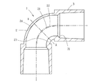
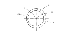
図1はこの発明の合成樹脂製曲管継手の一例を示す断面図、図2は図1のA−A線における断面図である。
図で、1は90度大曲エルボである合成樹脂製曲管継手で、硬質塩化ビニル樹脂を射出成形して製造されている。この曲管継手1は90度曲り部2の両端に接着用テーパー受口部3、3が一体に形成されている。受口部3、3は曲り部2の内径の中心軸線21に、受口部3、3の中心軸線を一致させて形成され、この受口部3、3の奥側に被接続管の挿入量を規定するストッパー段部31が形成されている。
Next, the best mode for carrying out the present invention will be described based on an embodiment shown in the drawings.
FIG. 1 is a cross-sectional view showing an example of a synthetic resin bent pipe joint of the present invention, and FIG. 2 is a cross-sectional view taken along the line AA of FIG.
In the figure, reference numeral 1 denotes a synthetic resin bent pipe joint which is a 90-degree large elbow, which is manufactured by injection molding a hard vinyl chloride resin. The bent pipe joint 1 is integrally formed with adhesive
90度曲り部2の外径の中心軸線22は、内径の中心軸線21より曲りの内側にずれている。このように曲り部2の外径の中心軸線22が内径の中心軸線21より曲りの内側にずれていることにより、図2に示すように、曲り部2の内側の厚肉部23は外側の薄肉部24より、中心軸線のずれた寸法分だけ肉厚となり、内側の厚肉部23から外側の薄肉部24に向けて徐々に肉厚が薄くなるよう変化している。
The
この例において、薄肉部24は従来の曲管継手の曲り部の肉厚と同一肉厚または多少薄肉であってもよい。そして、曲り部2の内側の厚肉部23の肉厚は、集中応力および疲労による破壊を防止可能な厚さとなされていればよい。
例えば、呼び径200mm以下の曲管継手であれば、薄肉部24の肉厚を従来の曲管継手の曲り部の肉厚と同一とし、厚肉部23の肉厚を薄肉部24の肉厚の1.5倍の肉厚にすればよい。
また、呼び径が250〜300と大口径の曲管継手であれば、従来から強度的に安全率を高く設計されているので、厚肉部23の肉厚を薄肉部24の肉厚の1.3〜1.5倍の肉厚に設定し、薄肉部24の肉厚を従来の曲管継手の曲り部よりも薄くして、継手の重量が従来の継手と略同重量となるよう薄肉部24の肉厚を決めてもよい。
In this example, the
For example, in the case of a bent pipe joint having a nominal diameter of 200 mm or less, the thickness of the
In addition, if the bent pipe joint has a nominal diameter of 250 to 300 and a large diameter, it has been conventionally designed to have a high safety factor in terms of strength. Therefore, the thickness of the
このような肉厚とすると、曲り部2の内側が補強され、集中応力や繰り返し応力がかかっても発生する応力が低減され、破壊されることはない。しかも、曲り部2の内側が補強されることにより曲り部2の外側への応力の影響も低減されるので、薄肉部24の肉厚を従来の曲管継手の曲り部の肉厚より薄くすることも可能である。薄肉部24の占める面積は曲り部2の外側に位置するため、厚肉部23の占める面積よりはるかに広いので、薄肉部24の肉厚を僅か減少させることでも曲管継手1の重量を大きく減少させることができる。
従って、継手重量の増加を少なくするか増加することがなくても、集中応力や繰り返し応力に対する十分な強度補強が達成される。
With such a wall thickness, the inside of the
Therefore, sufficient strength reinforcement against concentrated stress and repetitive stress can be achieved without reducing or increasing the joint weight.
尚、この発明において、曲管継手としては、90度大曲エルボからなる曲管継手に限られるものではなく、曲り部を有する曲管継手であればよく、例えば、60度大曲エルボ、45度大曲エルボ、30度大曲エルボであってもよい。また、曲管継手がエルボ継手であってもよい。 In the present invention, the curved pipe joint is not limited to a curved pipe joint made of a 90-degree large elbow, and may be a curved pipe joint having a bent portion, for example, a 60-degree large elbow, a 45-degree large bend. An elbow or a 30 degree large elbow may be used. Further, the curved pipe joint may be an elbow joint.
1 合成樹脂製曲管継手(90度大曲エルボ)
2 曲り部
21 曲り部2の内径の中心軸線
22 曲り部2の外径の中心軸線
23 曲り部2の内側の厚肉部
24 曲り部2の外側の薄肉部
3 接着用テーパー受口部
31 ストッパー段部
1 Synthetic resin curved pipe fittings (90-degree large elbow)
2
Claims (2)
Priority Applications (1)
| Application Number | Priority Date | Filing Date | Title |
|---|---|---|---|
| JP2004107574A JP2005291379A (en) | 2004-03-31 | 2004-03-31 | Synthetic resin bent pipe fittings |
Applications Claiming Priority (1)
| Application Number | Priority Date | Filing Date | Title |
|---|---|---|---|
| JP2004107574A JP2005291379A (en) | 2004-03-31 | 2004-03-31 | Synthetic resin bent pipe fittings |
Publications (1)
| Publication Number | Publication Date |
|---|---|
| JP2005291379A true JP2005291379A (en) | 2005-10-20 |
Family
ID=35324534
Family Applications (1)
| Application Number | Title | Priority Date | Filing Date |
|---|---|---|---|
| JP2004107574A Withdrawn JP2005291379A (en) | 2004-03-31 | 2004-03-31 | Synthetic resin bent pipe fittings |
Country Status (1)
| Country | Link |
|---|---|
| JP (1) | JP2005291379A (en) |
Cited By (6)
| Publication number | Priority date | Publication date | Assignee | Title |
|---|---|---|---|---|
| JP2007198534A (en) * | 2006-01-27 | 2007-08-09 | Sekisui Chem Co Ltd | Pipe fitting |
| JP2009241645A (en) * | 2008-03-28 | 2009-10-22 | Panasonic Electric Works Co Ltd | Non-contact type power supply system |
| JP2020029882A (en) * | 2018-08-21 | 2020-02-27 | 積水化学工業株式会社 | Bent pipe structure and fittings |
| JP2022064978A (en) * | 2018-05-28 | 2022-04-26 | 株式会社オンダ製作所 | Resin fittings |
| JP2023126826A (en) * | 2017-07-27 | 2023-09-12 | 株式会社オンダ製作所 | Resin elbow joint |
| JP2024041170A (en) * | 2022-09-14 | 2024-03-27 | クラレプラスチックス株式会社 | Elbow for air conditioning piping |
-
2004
- 2004-03-31 JP JP2004107574A patent/JP2005291379A/en not_active Withdrawn
Cited By (12)
| Publication number | Priority date | Publication date | Assignee | Title |
|---|---|---|---|---|
| JP2007198534A (en) * | 2006-01-27 | 2007-08-09 | Sekisui Chem Co Ltd | Pipe fitting |
| JP2009241645A (en) * | 2008-03-28 | 2009-10-22 | Panasonic Electric Works Co Ltd | Non-contact type power supply system |
| JP2023126826A (en) * | 2017-07-27 | 2023-09-12 | 株式会社オンダ製作所 | Resin elbow joint |
| JP7536228B2 (en) | 2017-07-27 | 2024-08-20 | 株式会社オンダ製作所 | Plastic elbow fitting |
| JP2022064978A (en) * | 2018-05-28 | 2022-04-26 | 株式会社オンダ製作所 | Resin fittings |
| JP7303991B2 (en) | 2018-05-28 | 2023-07-06 | 株式会社オンダ製作所 | Resin joint |
| JP2023126827A (en) * | 2018-05-28 | 2023-09-12 | 株式会社オンダ製作所 | Resin joint |
| JP7536229B2 (en) | 2018-05-28 | 2024-08-20 | 株式会社オンダ製作所 | Plastic joints |
| JP2024144693A (en) * | 2018-05-28 | 2024-10-11 | 株式会社オンダ製作所 | Plastic joints |
| JP7677517B2 (en) | 2018-05-28 | 2025-05-15 | 株式会社オンダ製作所 | Plastic joints |
| JP2020029882A (en) * | 2018-08-21 | 2020-02-27 | 積水化学工業株式会社 | Bent pipe structure and fittings |
| JP2024041170A (en) * | 2022-09-14 | 2024-03-27 | クラレプラスチックス株式会社 | Elbow for air conditioning piping |
Similar Documents
| Publication | Publication Date | Title |
|---|---|---|
| JP5758640B2 (en) | Tube fitting | |
| US7857357B2 (en) | Reinforced pipe fitting with eccentric flow path | |
| CN109424807B (en) | Tongue-and-groove joint | |
| JP2005291379A (en) | Synthetic resin bent pipe fittings | |
| KR101452357B1 (en) | A Conduit Connecting Device | |
| EP3489561A1 (en) | Plastic valve capable of preventing distortion | |
| AU2020223900A1 (en) | Fitting for connecting pipes, in particular flexible pipes | |
| CZ2003312A3 (en) | Improved casing joints | |
| JP4516339B2 (en) | Synthetic resin joint portion structure and synthetic resin joint using the synthetic resin joint portion structure | |
| JPH11287378A (en) | Branch pipe | |
| JPH10148281A (en) | Steel pipe screw fittings | |
| JP2012237351A (en) | Synthetic resin pipe fitting | |
| JP2006189080A (en) | Branch fitting | |
| JP2003156186A (en) | Pressure line | |
| JP6372038B2 (en) | Pipe fitting | |
| JP3830482B2 (en) | Curved pipe joint structure of FRPM pipe | |
| UA128748C2 (en) | Threaded connection including and intermediate shoulder | |
| JP4288082B2 (en) | Pipe fitting | |
| EP3754241B1 (en) | Central insertion connector | |
| CN116964365B (en) | Pipe joint | |
| JP2007198534A (en) | Pipe fitting | |
| JP4667992B2 (en) | Joint body | |
| JP4861053B2 (en) | Connection method of joint body | |
| JP2021085428A (en) | Hose connection structure | |
| JP4659558B2 (en) | Curved pipe and pipe branching structure using the same |
Legal Events
| Date | Code | Title | Description |
|---|---|---|---|
| A621 | Written request for application examination |
Free format text: JAPANESE INTERMEDIATE CODE: A621 Effective date: 20061117 |
|
| A977 | Report on retrieval |
Effective date: 20091015 Free format text: JAPANESE INTERMEDIATE CODE: A971007 |
|
| A131 | Notification of reasons for refusal |
Free format text: JAPANESE INTERMEDIATE CODE: A131 Effective date: 20091111 |
|
| A761 | Written withdrawal of application |
Free format text: JAPANESE INTERMEDIATE CODE: A761 Effective date: 20091225 |