JP2005291354A - Detachable cold insulation cover - Google Patents
Detachable cold insulation cover Download PDFInfo
- Publication number
- JP2005291354A JP2005291354A JP2004106800A JP2004106800A JP2005291354A JP 2005291354 A JP2005291354 A JP 2005291354A JP 2004106800 A JP2004106800 A JP 2004106800A JP 2004106800 A JP2004106800 A JP 2004106800A JP 2005291354 A JP2005291354 A JP 2005291354A
- Authority
- JP
- Japan
- Prior art keywords
- cold insulation
- insulation cover
- pipe connection
- cover
- detachable
- Prior art date
- Legal status (The legal status is an assumption and is not a legal conclusion. Google has not performed a legal analysis and makes no representation as to the accuracy of the status listed.)
- Pending
Links
- 238000009413 insulation Methods 0.000 title claims abstract description 40
- 239000003949 liquefied natural gas Substances 0.000 claims description 29
- 239000012774 insulation material Substances 0.000 claims description 17
- 238000012546 transfer Methods 0.000 claims description 7
- VNWKTOKETHGBQD-UHFFFAOYSA-N methane Chemical compound C VNWKTOKETHGBQD-UHFFFAOYSA-N 0.000 abstract description 4
- 239000012212 insulator Substances 0.000 abstract description 2
- 238000007710 freezing Methods 0.000 description 7
- 230000008014 freezing Effects 0.000 description 7
- 238000007689 inspection Methods 0.000 description 6
- JOYRKODLDBILNP-UHFFFAOYSA-N Ethyl urethane Chemical compound CCOC(N)=O JOYRKODLDBILNP-UHFFFAOYSA-N 0.000 description 4
- 229920005830 Polyurethane Foam Polymers 0.000 description 4
- 238000012423 maintenance Methods 0.000 description 4
- 239000011496 polyurethane foam Substances 0.000 description 4
- 229910001220 stainless steel Inorganic materials 0.000 description 4
- 239000010935 stainless steel Substances 0.000 description 4
- 238000005187 foaming Methods 0.000 description 3
- XLYOFNOQVPJJNP-UHFFFAOYSA-N water Substances O XLYOFNOQVPJJNP-UHFFFAOYSA-N 0.000 description 3
- 230000000694 effects Effects 0.000 description 2
- 230000007613 environmental effect Effects 0.000 description 2
- 239000011491 glass wool Substances 0.000 description 2
- 238000002347 injection Methods 0.000 description 2
- 239000007924 injection Substances 0.000 description 2
- 239000011810 insulating material Substances 0.000 description 2
- 239000000463 material Substances 0.000 description 2
- 238000003466 welding Methods 0.000 description 2
- 239000004698 Polyethylene Substances 0.000 description 1
- XUIMIQQOPSSXEZ-UHFFFAOYSA-N Silicon Chemical compound [Si] XUIMIQQOPSSXEZ-UHFFFAOYSA-N 0.000 description 1
- 229910000831 Steel Inorganic materials 0.000 description 1
- XAGFODPZIPBFFR-UHFFFAOYSA-N aluminium Chemical compound [Al] XAGFODPZIPBFFR-UHFFFAOYSA-N 0.000 description 1
- 229910052782 aluminium Inorganic materials 0.000 description 1
- 239000003795 chemical substances by application Substances 0.000 description 1
- 230000008602 contraction Effects 0.000 description 1
- 238000001816 cooling Methods 0.000 description 1
- 239000010779 crude oil Substances 0.000 description 1
- 239000011888 foil Substances 0.000 description 1
- 239000007789 gas Substances 0.000 description 1
- 238000000034 method Methods 0.000 description 1
- 239000003345 natural gas Substances 0.000 description 1
- 238000012856 packing Methods 0.000 description 1
- -1 polyethylene Polymers 0.000 description 1
- 229920000573 polyethylene Polymers 0.000 description 1
- 238000012545 processing Methods 0.000 description 1
- 238000011084 recovery Methods 0.000 description 1
- 229910052710 silicon Inorganic materials 0.000 description 1
- 239000010703 silicon Substances 0.000 description 1
- 239000007921 spray Substances 0.000 description 1
- 239000010959 steel Substances 0.000 description 1
- 125000000391 vinyl group Chemical group [H]C([*])=C([H])[H] 0.000 description 1
- 229920002554 vinyl polymer Polymers 0.000 description 1
Images

Landscapes
- Thermal Insulation (AREA)
Abstract
Description
本発明は、液化天然ガスの移送(受入・払出)ラインにおける配管接続部を覆う着脱自在な保冷カバーの技術分野に関する。 The present invention relates to a technical field of a detachable cold insulation cover that covers a pipe connection portion in a liquefied natural gas transfer (acceptance / dispensing) line.
接岸したLNG船から液化天然ガスを荷揚げする際には、LNG船に設けた接続フランジに、陸側のローディングアームに設けた接続フランジが接続され、荷揚げ作業が終了すると分離される。しかし、液化天然ガスの荷揚げ作業中はローディングアームは極低温になるため作業が完了する頃には、通常、接続フランジが凍結している。そこで、従来では、凍結した接続フランジに水をかけて凍結を解除してから接続フランジを分離するようにしていた。なお、ローディングアームを用いたLNG受入基地についての提案が開示されている(例えば、特許文献1参照)。 When unloading liquefied natural gas from a LNG ship that has berthed, the connection flange provided on the loading arm on the land side is connected to the connection flange provided on the LNG ship, and separated when the unloading operation is completed. However, during the liquefied natural gas unloading operation, the loading arm is at a very low temperature, so that the connection flange is usually frozen when the operation is completed. Therefore, conventionally, the connection flange is separated after the frozen connection flange is poured with water to release the freezing. In addition, the proposal about the LNG receiving base using a loading arm is disclosed (for example, refer patent document 1).
また、陸側に設けられる液化天然ガスの受入配管には保冷カバーが巻装されている。その保冷カバーは、例えば、グラスウールやポリエチレンシート、(注入発泡による)ポリウレタンフォーム、ポリウレタンフォームカバー、防湿剤等からなる保冷材を配管の外周に積層状態に取り付け、さらにその外側を(例えば、着色ステンレス鋼板等からなる)外装板で覆うようにしていた。
ローディングアームによりLNG船から荷揚げ作業を行う場合、特に、雨天時や湿度の高い時、冬期等では、凍結が甚だしくなるため、従来のように、凍結した接続フランジに水をかけて凍結を解除する方法では、長時間を要することがあった。 When unloading work from an LNG ship using a loading arm, especially during rainy weather or when the humidity is high, the freezing will be severe in winter, etc., so as to release the freezing by applying water to the frozen connection flange as before. The method may take a long time.
また、陸側に設けられる液化天然ガスの受入配管は、受け入れ時と通常時とでは、温度差が大きくなるため、配管の度重なる伸縮により、配管接続部からガスが漏洩することがあった。そのような場合には、外装板を取り除いた後、内部に積層してある保冷材をも取り除いて、漏洩の原因を究明して補修を行い、新しい保冷材を充填し直し外装板も新しいものに取り替えるようにしていた。 In addition, the liquefied natural gas receiving pipe provided on the land side has a large temperature difference between the receiving time and the normal time, and therefore gas may leak from the pipe connecting portion due to repeated expansion and contraction of the piping. In such a case, after removing the exterior plate, remove the cold insulation material stacked inside, investigate the cause of the leak, repair it, refill with new cold insulation material, and the exterior plate is also new. I was trying to replace it.
しかし、このような点検と取り替えの作業は、多大の手間と時間を要し、復旧には、最低3日が必要とされ、環境条件が不良な場合には、さらに長い作業日数が必要とされていた。即ち、保冷カバーを取り外す時には、保冷材が周囲に飛散するのを防止するために、フランジ接続部の周囲に囲いを設ける必要があり、その作業が煩瑣であった。また、ポリウレタンフォームカバーの加工やポリウレタンフォームの注入発泡は現場で行われるため段取りが大変面倒であった。 However, such inspection and replacement work requires a great deal of labor and time, and at least 3 days are required for recovery, and even longer work days are required if environmental conditions are poor. It was. That is, when removing the cold insulation cover, it is necessary to provide an enclosure around the flange connection portion in order to prevent the cold insulation material from being scattered around, and this work is troublesome. In addition, the processing of the polyurethane foam cover and the injection foaming of the polyurethane foam are performed in the field, so the setup is very troublesome.
本発明は、このような実情に鑑みてなされ、ローディングアームを用いた液化天然ガスの荷役終了後に直ちに配管接続部を分離できる着脱自在な保冷カバーを提供することを目的とし、また、配管接続部の保守点検が容易で再度の使用が可能となる着脱自在な保冷カバーを提供することをも目的とする。 The present invention has been made in view of such circumstances, and an object of the present invention is to provide a detachable cold insulation cover capable of separating a pipe connection portion immediately after the end of cargo handling of liquefied natural gas using a loading arm. Another object of the present invention is to provide a detachable cooling cover that is easy to maintain and can be used again.
本発明に係る着脱自在な保冷カバーは、上述の課題を解決するための手段を、以下のように構成している。
(1)液化天然ガスの移送ラインにおける配管接続部を覆う着脱自在な保冷カバーにあって、
円弧状となるように接続可能な複数の外装板の内側には、前記配管接続部を覆う保冷材が設けられ、かつ、前記外装板の対向し合う接続部には、掛脱自在な掛止部材が設けられている。
The detachable cold insulation cover according to the present invention has the following means for solving the above-described problems.
(1) In a detachable cold insulation cover covering the pipe connection part in the liquefied natural gas transfer line,
Inside the plurality of exterior plates that can be connected in a circular arc shape, a cold insulation material is provided to cover the pipe connection portion, and the opposing connection portions of the exterior plate are detachably latched. A member is provided.
このような構成によれば、保冷カバーを配管接続部に装着することで、配管接続部を保冷し、かつ凍結を防止できると共に、掛止部材の掛止状態を解除して保冷カバーを取り除けば、(凍結していない)配管接続部を容易に分離することができる。また、その配管接続部を保守点検することもできる。そして、保守点検が終了した後には、元通りに保冷カバーを配管接続部に被せて掛止部材を掛止すれば、その保冷カバーを再度使用することができる。なお、移送ラインには、受入ライン及び払出ラインが含まれる。 According to such a configuration, by attaching the cold insulation cover to the pipe connection portion, the pipe connection portion can be kept cold and freezing can be prevented, and the latching state of the hooking member can be released to remove the cold insulation cover. , The pipe connection (not frozen) can be easily separated. In addition, the pipe connection part can be inspected and maintained. Then, after the maintenance inspection is completed, the cold insulation cover can be used again by covering the pipe connection portion with the cold insulation cover and hooking the hooking member. The transfer line includes a receiving line and a payout line.
(2)このような着脱自在な保冷カバーは、LNG船に接続されるローディングアームに設けられた配管接続部を覆うよう使用してもよい。このようにすれば、ローディングアームによりLNG船から荷揚げ作業を行う際に、荷揚げ作業中に配管接続部を保冷することができ、かつ、その凍結を防止することができる。従って、荷揚げ作業が終了した後、直ちに保冷カバーを分離して取り除けば、配管接続部は凍結していないため、容易に分離することができる。 (2) Such a detachable cold insulation cover may be used so as to cover a pipe connection portion provided in a loading arm connected to the LNG ship. If it does in this way, when unloading work from an LNG ship by a loading arm, a piping connection part can be kept cold during unloading work, and the freezing can be prevented. Therefore, if the cold insulation cover is separated and removed immediately after the unloading operation is completed, the pipe connection portion is not frozen and can be easily separated.
本発明に係る着脱自在な保冷カバーは、円弧状となるように接続可能な複数の外装板の内側に配管接続部を覆う保冷材を設け、かつ、外装板の対向し合う接続部に掛脱自在な掛止部材を設けたので、保冷カバーによって配管接続部を保冷し、かつ凍結を防止できると共に、掛止部材の掛止状態を解除して保冷カバーを取り除けば、(凍結していない)配管接続部を容易に分離することができ、また、配管接続部の保守点検も可能となる。そして、保守点検後には、保冷カバーを取り付けて掛止部材を掛止すれば、その保冷カバーを再度使用することができる。 The detachable cold insulation cover according to the present invention is provided with a cold insulation material covering a pipe connection portion inside a plurality of exterior plates connectable so as to form an arc shape, and is attached to and detached from opposing connection portions of the exterior plate. Since the free hooking member is provided, the pipe connection can be kept cold by the cold cover and freezing can be prevented, and if the cold cover is removed by releasing the hooked state of the hook member (not frozen) The pipe connection portion can be easily separated, and maintenance and inspection of the pipe connection portion is also possible. And after maintenance inspection, if a cold insulation cover is attached and a latching member is latched, the cold insulation cover can be used again.
以下に、本発明の最良の実施の形態に係る着脱自在な保冷カバーについて図面を参照しつつ詳細に説明する。
〔実施の形態1〕
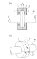
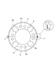
図1は、着脱自在な保冷カバー(以下、保冷カバーという)を配管接続部に取り付けた状態を示し、(a)はその断面図、(b)は斜視図、図2は保冷カバーを内側から見た正面図であり、これらの図に示される保冷カバーC1は、例えば、図5に示すように、接岸したLNG船1に接続されるローディングアーム(本発明でいう液化天然ガスの移送ライン)3の配管接続部4に着脱自在に装着して使用される。なお、図5は荷揚げ中のLNG船1と発電所の液化天然ガスの受入配管(本発明でいう液化天然ガスの移送ライン)2の一部を示し、11は水噴霧設備、12は低発泡設備、13は防液堤、14,15は原油タンク、16はLNGタンクである。
Hereinafter, a detachable cold insulation cover according to the best embodiment of the present invention will be described in detail with reference to the drawings.
[Embodiment 1]
FIG. 1 shows a state in which a detachable cold insulation cover (hereinafter referred to as a cold insulation cover) is attached to a pipe connection part, (a) is a cross-sectional view thereof, (b) is a perspective view, and FIG. FIG. 5 is a front view of the cold insulation cover C1 shown in FIG. 5. For example, as shown in FIG. 5, a loading arm (liquefied natural gas transfer line referred to in the present invention) connected to the LNG ship 1 berthing is shown in FIG. 3 is used by being detachably attached to the
その配管接続部4は、LNG船1に設けられる接続フランジ4aと、ローディングアーム3に設けられる接続フランジ4bと、からなり、LNG船1から荷揚げ作業を行うときにのみボルト,ナット等の締結部材(図示省略)によって接続固定され、荷揚げ作業が終了すると、直ちに、分離されるものである。
The
この保冷カバーC1は、半割れ状に形成されて互いに円弧状となるように接続可能な一対の外装板(ステンレス鋼板等からなる)5,5と、配管接続部4を覆うために外装板5,5の内面に設けられる保冷材6,6と、からなり、その一対の外装板5,5の対向し合う接続部には掛脱自在な掛止部材7,7が設けられ、配管接続部4に対して着脱自在に装着できるように構成されている。
The cold insulation cover C1 is formed in a half-cracked shape and can be connected to form a circular arc shape with each other, and a pair of exterior plates (made of stainless steel plate or the like) 5, 5 and an
その外装板5の内面に設けられる保冷材6には、図2に示すように、配管接続部4の締結部材(ボルト,ナット等)を嵌め込むための逃げ穴6a,6bが形成されている。その保冷材6は、例えば、外装板5の内面にウレタンカバーを接着することにより形成することができる。また、掛止部材7は、掛止部71と、掛止部71に掛止される被掛止部72とからなり、ワンタッチで掛脱操作可能なものが好適である。
As shown in FIG. 2,
このような保冷カバーC1は、円弧状に接合した一対の外装板5,5の内側同士を対向させて2枚合せで一つの配管接続部4を覆うようにして使用する。従って、配管接続部4に装着された状態では、図1(a)(b)に示すように、配管接続部4の周囲を覆う保冷材6は外装板5によって完全に覆い隠されている。
Such a cold insulation cover C1 is used in such a manner that two
このような構成によれば、ローディングアーム3を介してLNG船1から荷揚げ作業を行う場合に、荷揚げ作業中に配管接続部4の凍結を効果的に防止することができる。従って、荷揚げ作業が終了した後、掛止部材7を外して直ちに保冷カバーC1を4つの部分に分離して取り除けば、凍結していない配管接続部4を容易に分離することができる。なお、雨天時や降雪時等には、荷揚げ作業中に保冷カバーC1をビニールシートで覆っておくと、凍結防止効果が向上する。
According to such a configuration, when the unloading operation is performed from the LNG ship 1 via the
〔実施の形態2〕
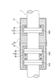
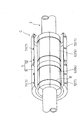
図3は、着脱自在な保冷カバー(以下、保冷カバーという)C2を配管接続部4に取り付けた状態の断面図、図4はその分解斜視図である。これらの図に示される保冷カバーC2は、例えば、図5に示すように、発電所の液化天然ガスの受入配管2における配管接続部(図示省略)に着脱自在に装着して使用される。なお、前実施の形態と同一部材または同等部材には同一符号を付し、その説明を省略する。
[Embodiment 2]
FIG. 3 is a cross-sectional view of a state in which a detachable cold insulation cover (hereinafter referred to as a cold insulation cover) C2 is attached to the
この場合、3つの配管接続部41,42,43を、保冷カバーC2で覆っており、まず、配管接続部41,42,43の凹凸部にアルミ箔付きのグラスウール(1層目)61を巻き付けてポリエステルシート62で覆い、さらに、その外側を管軸方向に6分割したウレタンカバー(2層目)63で覆うことで保冷材6を構成し、その保冷材6の外側をステンレスバンド8で締結して配管接続部41,42,43に固定した後、その外側を半割り状の外装板5で覆うようにしている。そのウレタンカバーの内面は、FRPでコーティングされ、含水を防止している。
In this case, the three
従って、配管接続部41,42,43に装着された状態では、図3に示すように、保冷材6は外装板5によって完全に覆い隠されている。図示の例では、保冷材6は、2セットに分離し、外装板5は、それぞれ半割れ状に形成される円弧状の板部材51,52を中央部で重ね継ぎ(ラップ接続)により接合して、その接合部をシリコンパッキンにより密封している。このような重ね継ぎにより、縦方向(管軸に沿う方向)及び横方向(管軸に垂直な方向)に板部材51,52を分割することができるため、着脱時の取り扱いが容易となる。なお、図示は省略するが、半割れ状に形成される円弧状の板部材51,52同士は中央部で溶接してもよく、その場合には、例えば、接合部をフランジ状に形成して、そのフランジ同士をスポット溶接により接合してもよい。
Therefore, in a state where the
このような構成によれば、板部材51,52(外装板5)を分離して、ステンレスバンド8を取り外して保冷材6を取り除けば、直ちに、配管接続部41,42,43を点検することができる。そして、点検終了後には、配管接続部41,42,43に保冷材6,6を取り付けて板部材51,52(外装板5)で覆えば、各部材の再度の使用が可能となる。また、このような作業は、保冷材6が飛散することもなく、従って、従来のように、囲いを設ける必要もなく、きわめて高能率に行うことができ、コスト安に配管接続部4の保守点検が可能となる。
According to such a structure, if the
なお、本発明は、以上の実施の形態に限定されることなく、発明の趣旨を逸脱しない限度において、使用箇所や使用条件、環境条件等に応じて、適宜、改良、変更等は自由である。例えば、実施の形態1における保冷カバーC1の外装板5は、半割れ状ではなく、互いに円弧状となるように接続可能であれば、3分割又はそれ以上に分割されてもよく、左右の外装板5,5を一体化してもよい。また、その保冷カバーC1は、比較的に頻繁に着脱される配管接続部であれば、タンクローリ(車両)へのローディング時や、タンクローリからのローディング時に使用される配管接続部等にも適用可能であるのは言うまでもない。
It should be noted that the present invention is not limited to the above-described embodiment, and can be freely improved, modified, etc. as appropriate according to the location of use, use conditions, environmental conditions, etc., without departing from the spirit of the invention. . For example, the
また、実施の形態2における保冷材6を構成するウレタンカバー63は、6分割ではなく、2分割や3分割、4分割等であってもよく、その素材は、保冷効果のあるその他の素材により形成されてもよい。あるいは、保冷材6の一部または全てを外装板5の内面に一体化させてもよい。また、外装板5は、半割れ状ではなく、互いに円弧状となるように接続可能であれば、3分割又はそれ以上の板部材に分割されてもよい。さらに、板部材51,52同士を重ね継ぎや溶接により接合して外装板5を形成するのではなく、単一の板部材で外装板5を形成してもよい。また、複数に分割された板部材を3つ以上組み合わせて外装板5を形成してもよい。あるいは、その保冷カバーC2は、地上に設けられた液化天然ガスの受入ラインの配管接続部に限られることなく、例えば、LNG船上の払出ライン(又は受入ライン)の配管接続部にも適用できるのは言うまでもない。
In addition, the
1…LNG船、2…移送(受入)ライン、3…ローディングアーム、4…配管接続部、C1,C2…保冷カバー、5…外装板、6…保冷材、7…掛止部材 DESCRIPTION OF SYMBOLS 1 ... LNG ship, 2 ... Transfer (acceptance) line, 3 ... Loading arm, 4 ... Pipe connection part, C1, C2 ... Cold insulation cover, 5 ... Exterior board, 6 ... Cold insulation material, 7 ... Hanging member
Claims (2)
円弧状となるように接続可能な複数の外装板の内側には、前記配管接続部を覆う保冷材が設けられ、かつ、前記外装板の対向し合う接続部には、掛脱自在な掛止部材が設けられていることを特徴とする着脱自在な保冷カバー。 A detachable cold insulation cover covering a pipe connection part in a liquefied natural gas transfer line,
Inside the plurality of exterior plates that can be connected in a circular arc shape, a cold insulation material is provided to cover the pipe connection portion, and the opposing connection portions of the exterior plate are detachably latched. A detachable cold insulation cover characterized in that a member is provided.
Priority Applications (1)
| Application Number | Priority Date | Filing Date | Title |
|---|---|---|---|
| JP2004106800A JP2005291354A (en) | 2004-03-31 | 2004-03-31 | Detachable cold insulation cover |
Applications Claiming Priority (1)
| Application Number | Priority Date | Filing Date | Title |
|---|---|---|---|
| JP2004106800A JP2005291354A (en) | 2004-03-31 | 2004-03-31 | Detachable cold insulation cover |
Publications (1)
| Publication Number | Publication Date |
|---|---|
| JP2005291354A true JP2005291354A (en) | 2005-10-20 |
Family
ID=35324513
Family Applications (1)
| Application Number | Title | Priority Date | Filing Date |
|---|---|---|---|
| JP2004106800A Pending JP2005291354A (en) | 2004-03-31 | 2004-03-31 | Detachable cold insulation cover |
Country Status (1)
| Country | Link |
|---|---|
| JP (1) | JP2005291354A (en) |
Cited By (1)
| Publication number | Priority date | Publication date | Assignee | Title |
|---|---|---|---|---|
| WO2024145093A1 (en) * | 2022-12-29 | 2024-07-04 | Ge Infrastructure Technology Llc | Radiation shield for a gaseous fuel circuit |
-
2004
- 2004-03-31 JP JP2004106800A patent/JP2005291354A/en active Pending
Cited By (2)
| Publication number | Priority date | Publication date | Assignee | Title |
|---|---|---|---|---|
| WO2024145093A1 (en) * | 2022-12-29 | 2024-07-04 | Ge Infrastructure Technology Llc | Radiation shield for a gaseous fuel circuit |
| US12305576B2 (en) | 2022-12-29 | 2025-05-20 | Ge Vernova Infrastructure Technology Llc | Radiation shield for a gaseous fuel circuit |
Similar Documents
| Publication | Publication Date | Title |
|---|---|---|
| US5722463A (en) | External pipe reinforcing sleeve | |
| CN103635737B (en) | A Coupler for relative fixed structure fixed element | |
| CN105026819B (en) | The method for producing the sealing thermal insulation layer for storage container | |
| KR102096514B1 (en) | Thermally-insulating sealed tank built into a load-bearing structure | |
| US9676456B2 (en) | Arrangement for containment of liquid natural gas (LNG) | |
| CN107270115B (en) | Heat-insulating edge block for manufacturing tank wall | |
| CN204176159U (en) | Boats and ships and upper pipeline crossing cabin part thereof | |
| CN109073158B (en) | Thermally isolated sealed tank | |
| US9470367B2 (en) | Systems and methods for fluid containment | |
| RU2755830C2 (en) | Sealed and heat-insulated tank | |
| US3998350A (en) | Semi-membrane like container, heat-insulated fluid-tight tank embodying same and methods of making same | |
| US3008735A (en) | Pipe coupling and method for interconnecting pipes | |
| SK2542003A3 (en) | Method of reinforcing an existing metal structure, method of reinforcing pipes and method of addition of spur lines to pipelines | |
| JP2005291354A (en) | Detachable cold insulation cover | |
| US10737748B2 (en) | Device for loading of bulk carriers and loading method | |
| CN105711756B (en) | The installation method of the vertical bearing insulation of A type independent liquid cargo tank inside bottom surfaces | |
| US20160001972A1 (en) | Inspection port for insulated tank car | |
| CN105711752B (en) | The installation method of the vertical bearing insulation of A type independent liquid cargo tank outer side bottom surfaces | |
| JP2020090971A (en) | Pipe repair method for methanol delivery | |
| KR20100010368U (en) | Foothold structure for maintaining lower slope area of LNG storage tank | |
| KR101623100B1 (en) | Lng carrier having a loading arm | |
| JP6468857B2 (en) | Removal method of existing oil pipe | |
| KR102490348B1 (en) | Pump tower base support of liquesification natural gas cargo | |
| JP3203252U (en) | Tube freezing container | |
| CN105711739B (en) | The installation method of the anti-pitching bearing insulation of A type independent liquid cargo tanks |
Legal Events
| Date | Code | Title | Description |
|---|---|---|---|
| A621 | Written request for application examination |
Effective date: 20061206 Free format text: JAPANESE INTERMEDIATE CODE: A621 |
|
| RD04 | Notification of resignation of power of attorney |
Effective date: 20080620 Free format text: JAPANESE INTERMEDIATE CODE: A7424 |
|
| A977 | Report on retrieval |
Effective date: 20090608 Free format text: JAPANESE INTERMEDIATE CODE: A971007 |
|
| A131 | Notification of reasons for refusal |
Free format text: JAPANESE INTERMEDIATE CODE: A131 Effective date: 20090612 |
|
| A521 | Written amendment |
Effective date: 20090811 Free format text: JAPANESE INTERMEDIATE CODE: A523 |
|
| A711 | Notification of change in applicant |
Free format text: JAPANESE INTERMEDIATE CODE: A711 Effective date: 20090819 |
|
| A521 | Written amendment |
Effective date: 20090819 Free format text: JAPANESE INTERMEDIATE CODE: A821 |
|
| A131 | Notification of reasons for refusal |
Free format text: JAPANESE INTERMEDIATE CODE: A131 Effective date: 20091002 |
|
| A521 | Written amendment |
Effective date: 20091001 Free format text: JAPANESE INTERMEDIATE CODE: A523 |
|
| A521 | Written amendment |
Effective date: 20091201 Free format text: JAPANESE INTERMEDIATE CODE: A523 |
|
| A02 | Decision of refusal |
Free format text: JAPANESE INTERMEDIATE CODE: A02 Effective date: 20091218 |