JP2005291346A - Automatic transmission control device - Google Patents
Automatic transmission control device Download PDFInfo
- Publication number
- JP2005291346A JP2005291346A JP2004106539A JP2004106539A JP2005291346A JP 2005291346 A JP2005291346 A JP 2005291346A JP 2004106539 A JP2004106539 A JP 2004106539A JP 2004106539 A JP2004106539 A JP 2004106539A JP 2005291346 A JP2005291346 A JP 2005291346A
- Authority
- JP
- Japan
- Prior art keywords
- vehicle speed
- lockup
- lock
- automatic transmission
- vehicle
- Prior art date
- Legal status (The legal status is an assumption and is not a legal conclusion. Google has not performed a legal analysis and makes no representation as to the accuracy of the status listed.)
- Granted
Links
Images

Classifications
-
- F—MECHANICAL ENGINEERING; LIGHTING; HEATING; WEAPONS; BLASTING
- F16—ENGINEERING ELEMENTS AND UNITS; GENERAL MEASURES FOR PRODUCING AND MAINTAINING EFFECTIVE FUNCTIONING OF MACHINES OR INSTALLATIONS; THERMAL INSULATION IN GENERAL
- F16H—GEARING
- F16H61/00—Control functions within control units of change-speed- or reversing-gearings for conveying rotary motion ; Control of exclusively fluid gearing, friction gearing, gearings with endless flexible members or other particular types of gearing
- F16H61/14—Control of torque converter lock-up clutches
- F16H61/143—Control of torque converter lock-up clutches using electric control means
-
- F—MECHANICAL ENGINEERING; LIGHTING; HEATING; WEAPONS; BLASTING
- F16—ENGINEERING ELEMENTS AND UNITS; GENERAL MEASURES FOR PRODUCING AND MAINTAINING EFFECTIVE FUNCTIONING OF MACHINES OR INSTALLATIONS; THERMAL INSULATION IN GENERAL
- F16H—GEARING
- F16H57/00—General details of gearing
- F16H57/0006—Vibration-damping or noise reducing means specially adapted for gearings
- F16H2057/0012—Vibration-damping or noise reducing means specially adapted for gearings for reducing drive line oscillations
-
- F—MECHANICAL ENGINEERING; LIGHTING; HEATING; WEAPONS; BLASTING
- F16—ENGINEERING ELEMENTS AND UNITS; GENERAL MEASURES FOR PRODUCING AND MAINTAINING EFFECTIVE FUNCTIONING OF MACHINES OR INSTALLATIONS; THERMAL INSULATION IN GENERAL
- F16H—GEARING
- F16H59/00—Control inputs to control units of change-speed- or reversing-gearings for conveying rotary motion
- F16H59/36—Inputs being a function of speed
- F16H59/38—Inputs being a function of speed of gearing elements
- F16H2059/405—Rate of change of output shaft speed or vehicle speed
-
- F—MECHANICAL ENGINEERING; LIGHTING; HEATING; WEAPONS; BLASTING
- F16—ENGINEERING ELEMENTS AND UNITS; GENERAL MEASURES FOR PRODUCING AND MAINTAINING EFFECTIVE FUNCTIONING OF MACHINES OR INSTALLATIONS; THERMAL INSULATION IN GENERAL
- F16H—GEARING
- F16H59/00—Control inputs to control units of change-speed- or reversing-gearings for conveying rotary motion
- F16H59/36—Inputs being a function of speed
- F16H59/44—Inputs being a function of speed dependent on machine speed, e.g. the vehicle speed
-
- F—MECHANICAL ENGINEERING; LIGHTING; HEATING; WEAPONS; BLASTING
- F16—ENGINEERING ELEMENTS AND UNITS; GENERAL MEASURES FOR PRODUCING AND MAINTAINING EFFECTIVE FUNCTIONING OF MACHINES OR INSTALLATIONS; THERMAL INSULATION IN GENERAL
- F16H—GEARING
- F16H59/00—Control inputs to control units of change-speed- or reversing-gearings for conveying rotary motion
- F16H59/48—Inputs being a function of acceleration
Landscapes
- Engineering & Computer Science (AREA)
- General Engineering & Computer Science (AREA)
- Mechanical Engineering (AREA)
- Control Of Fluid Gearings (AREA)
Abstract
Description
本発明は自動変速機の制御装置に関し、特に、ロックアップクラッチを備えたトルクコンバータを備えるものに関する。 The present invention relates to a control device for an automatic transmission, and more particularly to an apparatus having a torque converter having a lock-up clutch.
ロックアップクラッチを備えたトルクコンバータでは、ロックアップクラッチの前後差圧(ロックアップ差圧)を制御することで、ロックアップクラッチの締結・開放を行っており、コンバータ状態からロックアップ状態へ移行する際には、所定の初期差圧から徐々に差圧を上昇させてコンバータ状態からスリップ状態へ移行した後にロックアップクラッチの締結を行っている。 In a torque converter equipped with a lock-up clutch, the lock-up clutch is engaged and released by controlling the differential pressure across the lock-up clutch (lock-up differential pressure), and a transition is made from the converter state to the lock-up state. In this case, the lockup clutch is engaged after the differential pressure is gradually increased from a predetermined initial differential pressure to shift from the converter state to the slip state.
このようなロックアップクラッチの制御では、低車速からロックアップを行って燃費を向上させるものが知られている(特許文献1)。 In such control of the lockup clutch, one that improves the fuel consumption by performing lockup from a low vehicle speed is known (Patent Document 1).
この従来例では、
しかしながら、上記従来例では、登り坂などで車速が伸びない場合には、ロックアップ状態を維持したまま自動変速機の変速機比をLo側へ変更して伝達トルクを増幅しているが、登り坂の発進時などでトルクが不足した場合には、最Lo変速比で発進を行うため、さらに変速比をLo側へ変更することができず、低車速でロックアップを開始すると車速が伸びないばかりか、こもり音が発生するという問題があった。 However, in the above conventional example, when the vehicle speed does not increase due to an uphill, the transmission torque is amplified by changing the transmission ratio of the automatic transmission to Lo side while maintaining the lock-up state. If the torque is insufficient when starting on a hill, etc., the vehicle will start at the lowest gear ratio, so the gear ratio cannot be changed to the Lo side, and the vehicle speed will not increase if lockup is started at a low vehicle speed. In addition, there was a problem that a booming noise was generated.
そこで、本発明は上記問題点に鑑みてなされたもので、低車速からロックアップを行う際に車速の伸びを確保するとともに、こもり音の発生を防ぐことを目的とする。 Therefore, the present invention has been made in view of the above problems, and it is an object of the present invention to ensure an increase in vehicle speed and prevent the occurrence of a booming noise when locking up from a low vehicle speed.
本発明は、エンジンと自動変速機の間に介装されるとともにロックアップクラッチを備えたトルクコンバータと、車両の運転状態に基づいて、前記ロックアップクラッチに供給する差圧指令値を演算して、前記トルクコンバータのコンバータ状態とロックアップ状態とをスリップ状態を介して切り換えるロックアップ制御手段と、車両の発進後に、車速が予め設定した低車速を超えたときには、前記ロックアップ制御手段にロックアップの指令を行う早期ロックアップ指令手段と、を備えた自動変速機の制御装置において、
前記早期ロックアップ指令手段がロックアップの指令を行った後に、車速の上昇を監視する車速監視手段と、前記監視した車速の上昇が予め設定した値よりも低下したときには、前記ロックアップ制御手段に対してロックアップの解除を指令してコンバータ状態へ移行させる車速回復手段と、を備える。
The present invention calculates a differential pressure command value to be supplied to the lockup clutch based on a torque converter interposed between the engine and the automatic transmission and provided with a lockup clutch, and a driving state of the vehicle. A lockup control means for switching between a converter state and a lockup state of the torque converter via a slip state, and when the vehicle speed exceeds a preset low vehicle speed after starting the vehicle, the lockup control means locks up to the lockup control means. In an automatic transmission control device comprising an early lockup command means for commanding
After the early lockup command means issues a lockup command, vehicle speed monitoring means for monitoring the increase in vehicle speed, and when the monitored increase in vehicle speed falls below a preset value, the lockup control means Vehicle speed recovery means for instructing the release of the lockup to shift to the converter state.
本発明によれば、発進直後に所定の低車速を超えるとロックアップが開始され、車速が予め設定した値を上回って上昇する場合には、低車速からのロックアップにより燃費の向上を図ることができる。一方、急な登り坂などの発進で、車速の上昇が予め設定した値を下回ると、ロックアップが解除されてコンバータ状態へ移行するので、トルクの増幅とエンジン回転速度の上昇により速やかに車速を上昇させて、こもり音の発生を防止し、車両の動力性能を確保できるのである。 According to the present invention, lockup is started when a predetermined low vehicle speed is exceeded immediately after starting, and when the vehicle speed rises above a preset value, fuel efficiency is improved by locking up from the low vehicle speed. Can do. On the other hand, if the vehicle speed rises below a preset value due to a sudden start of an uphill or the like, the lockup is released and the converter enters the converter state.Therefore, the vehicle speed is quickly increased by increasing the torque and increasing the engine speed. By raising it, it is possible to prevent the generation of a booming noise and to secure the power performance of the vehicle.
以下、本発明の実施の形態について、図面に基づいて説明する。 Hereinafter, embodiments of the present invention will be described with reference to the drawings.
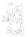
図1は、本発明のシステム構成を示す概略図である。 FIG. 1 is a schematic diagram showing the system configuration of the present invention.
この図1において、エンジン3にはトルクコンバータ5を備えた自動変速機4が連結され、トルクコンバータ5にはロックアップクラッチ6が配設されて運転状態に応じてロックアップ(締結状態)またはアンロックアップ(開放状態)を行うものである。
In FIG. 1, an automatic transmission 4 having a torque converter 5 is connected to the
トルクコンバータ5は、トルクコンバータ出力要素(タービン)と共に回転するロックアップクラッチ6を内蔵し、このロックアップクラッチ6は、トルクコンバータ入力要素(インペラ)に締結されるとき、トルクコンバータ5を入出力要素間が直結されたロックアップ状態にするものとする。 The torque converter 5 incorporates a lockup clutch 6 that rotates together with the torque converter output element (turbine). When the lockup clutch 6 is fastened to the torque converter input element (impeller), the torque converter 5 is connected to the input / output element. It shall be in the lock-up state where the space is directly connected.
ロックアップクラッチ6は、その両側(前後)におけるトルクコンバータアプライ圧Paとトルクコンバータレリーズ圧Prとの差圧Pa−Prに応動し、レリーズ圧Prがアプライ圧Paよりも高いとロックアップクラッチ6は開放されてトルクコンバータ入出力要素間を直結せず、レリーズ圧Prがアプライ圧Paよりも低くなる時にロックアップクラッチ6は締結されてトルクコンバータ入出力要素間を直結するものである。 The lock-up clutch 6 responds to a differential pressure Pa-Pr between the torque converter apply pressure Pa and the torque converter release pressure Pr on both sides (front and rear), and when the release pressure Pr is higher than the apply pressure Pa, the lock-up clutch 6 When the release pressure Pr is lower than the apply pressure Pa without being directly connected between the torque converter input / output elements, the lockup clutch 6 is engaged and directly connected between the torque converter input / output elements.
そして、上記後者の締結に際して、ロックアップクラッチ6の締結力、つまりロックアップ容量は、上記の差圧Pa−Prにより決定し、この差圧が大きい程ロックアップクラッチ6の締結力が増大してロックアップ容量を増大する。 When the latter is engaged, the fastening force of the lockup clutch 6, that is, the lockup capacity, is determined by the differential pressure Pa−Pr, and the greater the differential pressure, the greater the fastening force of the lockup clutch 6. Increase lockup capacity.
差圧Pa−Prは、周知のロックアップコントロールバルブ7により制御し、このロックアップコントロールバルブ7には、アプライ圧Paおよびレリーズ圧Prを相互に対向するように作用させ、更にアプライ圧Paと同方向にバネの付勢力を、またレリーズ圧Prと同方向にばね力を作用させ、同時にレリーズ圧Prと同方向に信号圧Psolをそれぞれ作用させる。 The differential pressure Pa-Pr is controlled by a well-known lockup control valve 7. The apply pressure Pa and the release pressure Pr are made to act on the lockup control valve 7 so as to oppose each other, and further, the same as the apply pressure Pa. The urging force of the spring is applied in the direction and the spring force is applied in the same direction as the release pressure Pr, and at the same time, the signal pressure Psol is applied in the same direction as the release pressure Pr.
ロックアップコントロールバルブ7は、これら油圧とバネの付勢力が釣り合うよう差圧Pa−Prを決定する。 The lockup control valve 7 determines the differential pressure Pa-Pr so that the hydraulic pressure and the biasing force of the spring are balanced.
ここでロックアップコントロールバルブ7にかかる信号圧Psolは、ポンプ圧Ppを元圧としてロックアップソレノイド8がデューティ信号Dutyに応じて作り出すものである。 Here, the signal pressure Psol applied to the lockup control valve 7 is generated by the lockup solenoid 8 in accordance with the duty signal Duty using the pump pressure Pp as a source pressure.
マイクロコンピュータなどで構成されるATコントローラ1は、車両の運転状態に応じてデューティ信号Dutyを決定し、ロックアップソレノイド8を介して差圧Pa−Prを制御する。
The
ATコントローラ1には、車両の走行状態やドライバーの運転状況を示す信号、例えば、自動変速機4に設けた入力軸回転センサ16からの入力軸回転速度Ni、トルクコンバータ5への入力回転速度(=エンジン回転速度Ne)を検出するインペラ回転センサ11からのポンプインペラ回転速度Np、アクセル操作量センサ14からのアクセル操作量APO(またはスロットル開度TVO)、車速センサ13からの車速VSPが入力される。
The
また、ATコントローラ1はエンジンコントローラ2からエンジン回転速度Ne、エンジントルクTeを受信する。
Further, the
そして、ATコントローラ1は、これらの検出信号によりロックアップクラッチ6の締結や解放あるいはスリップなどの制御を行う。
Then, the
ATコントローラ1は、車両の運転状態に応じてスムーズロックアップを行うもので、このスムーズロックアップは、例えば、アクセル操作量APOの変化が少なく、かつ車速VSPが緩やかに上昇する際に、コンバータ状態からスリップ状態を経てロックアップクラッチ6の締結を行うものである。
The AT
本発明では、発進後の低車速からロックアップを行うものであり、例えば、車速VSP=25Km/hでロックアップを完了させるためには、発進直後の車速VSP=10Km/h程度でスムースロックアップを開始する。この発進直後のスムースロックアップの期間中では、車速VSPの伸びを優先的に確保して運転性の低下とこもり音の発生を防止するものである。 In the present invention, the lockup is performed from the low vehicle speed after the start. For example, in order to complete the lockup at the vehicle speed VSP = 25 Km / h, the smooth lockup is performed at the vehicle speed VSP = 10 Km / h immediately after the start. To start. During the smooth lock-up period immediately after the start of the vehicle, the vehicle speed VSP is preferentially secured to prevent the drivability from being lowered and the occurrence of a booming noise.
次に、図2は、ATコントローラ1で行われる発進直後のスムースロックアップ制御の一例を示すフローチャートである。この処理は、ロックアップが完了するまで、あるいは、スムースロックアップが解除されるまで、所定の周期(例えば、数十msec)で繰り返して実行される。
Next, FIG. 2 is a flowchart showing an example of the smooth lockup control immediately after the start performed by the
S1では、実際の車速VSPを読み込んで、S2において、車速VSPがスムースロックアップを開始する所定の車速V1に達したか否かを判定する。車速V1に達していればS3へ進む一方、車速VSP<V1の場合にはそのまま処理を終了する。なお、スムースロックアップON制御の開始条件としては、車速VSPにアクセル操作量APOの条件を加えてもよい。 In S1, the actual vehicle speed VSP is read, and in S2, it is determined whether or not the vehicle speed VSP has reached a predetermined vehicle speed V1 at which smooth lockup is started. If the vehicle speed V1 has been reached, the process proceeds to S3, while if the vehicle speed VSP <V1, the process is terminated as it is. In addition, as a start condition of the smooth lockup ON control, the condition of the accelerator operation amount APO may be added to the vehicle speed VSP.
S3ではスムースロックアップの制御中であることを示すスムースロックアップフラグFluがONであるかを判定する。ONでない場合には、スムースロックアップを開始するためにS14へ進んで加速不足フラグFαがONでなければ、S15に進んでスムースロックアップフラグFluをONにセットするとともに、S16で監視用のタイマTmrとカウンタCntをクリアし、次回の処理からスムースロックアップ制御を実行する。なお、加速不足フラグFαがONの場合には、後述するS13のスムースロックアップOFF制御へ進む。 In S3, it is determined whether or not a smooth lockup flag Flu indicating that smooth lockup control is being performed is ON. If it is not ON, the process proceeds to S14 to start the smooth lockup, and if the underacceleration flag Fα is not ON, the process proceeds to S15 to set the smooth lockup flag Flu to ON and the monitoring timer in S16 Tmr and the counter Cnt are cleared, and smooth lockup control is executed from the next processing. When the acceleration shortage flag Fα is ON, the process proceeds to smooth lockup OFF control of S13 described later.
一方、S3の判定でスムースロックアップフラグFluがONの場合には、S4で監視用のタイマTmrをインクリメントした後、S5においてタイマTmrの値が所定期間ΔTに達したか否かを判定する。 On the other hand, if the smooth lockup flag Flu is ON in the determination of S3, after the monitoring timer Tmr is incremented in S4, it is determined in S5 whether or not the value of the timer Tmr has reached a predetermined period ΔT.
タイマTmrの値が所定期間ΔTに達していればS6に進み、達していない場合にはS10へ進んでロックアップクラッチ6を滑らかに締結するスムースロックアップON制御を行う。 If the value of the timer Tmr has reached the predetermined period ΔT, the process proceeds to S6, and if not, the process proceeds to S10 to perform smooth lockup ON control for smoothly engaging the lockup clutch 6.
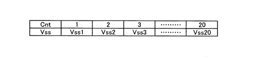
一方、タイマTmrの値が所定期間ΔTに達した場合には、S6に進んでカウンタCntの値をインクリメントした後、S7へ進んで、図3に示すように予め設定されたテーブルから、カウンタCntの値に応じた車速閾値Vssを検索する。図3のテーブルは、発進後に所定の車速V1を超えてから所定期間ΔT毎に車速VSPの伸びを監視するために、カウンタCntの値、換言すれば、スムースロックアップON制御の開始からの経過時間毎に、正常な発進であれば十分到達可能な車速を、車速閾値Vss(Cnt)として設定したものである。 On the other hand, when the value of the timer Tmr has reached the predetermined period ΔT, the process proceeds to S6 to increment the value of the counter Cnt, and then proceeds to S7, from the table set in advance as shown in FIG. The vehicle speed threshold value Vss corresponding to the value of is searched. The table of FIG. 3 shows the value of the counter Cnt, in other words, the progress from the start of the smooth lockup ON control, in order to monitor the growth of the vehicle speed VSP every predetermined period ΔT after the vehicle starts exceeding the predetermined vehicle speed V1. For each time, a vehicle speed that can be reached if the vehicle starts normally is set as a vehicle speed threshold Vss (Cnt).
次に、S8では上記S7で検索した発進直後のスムースロックアップON制御開始からの経過時間に対応する車速閾値Vssと現在の車速VSPを比較して、現在の車速VSPが車速閾値Vss(Cnt)よりも大きければ、車速VSPの伸びが正常であると判定してS9へ進み、次回の処理に備えてタイマTmrをクリアし、再び0からタイマTmrをカウントする準備を行う。その後、S10に進んで、運転状態に応じたロックアップ差圧を決定してロックアップクラッチの締結制御を実施する。 Next, in S8, the current vehicle speed VSP is compared with the current vehicle speed threshold Vss (Cnt) by comparing the vehicle speed threshold Vss corresponding to the elapsed time from the start of the smooth lockup ON control immediately after the start searched in S7 and the current vehicle speed VSP. If it is greater, the vehicle speed VSP is determined to be normal, and the process proceeds to S9 to clear the timer Tmr and prepare for counting the timer Tmr from 0 again in preparation for the next processing. Thereafter, the process proceeds to S10, in which a lockup differential pressure corresponding to the operating state is determined, and lockup clutch engagement control is performed.
一方、上記S8の判定で、現在の車速VSPがスムースロックアップON制御開始からの経過時間に対応する車速閾値Vss(Cnt)未満の場合には、車速VSPの伸びが低下したと判定してS11に進み、スムースロックアップフラグFluをOFFに設定してから、加速不足フラグFαをONにセットする。そして、S13に進んでスムースロックアップOFF制御を開始する。なお、スムースロックアップOFF制御は、締結途中または締結状態のロックアップクラッチ6を徐々に開放するもので、ロックアップクラッチ6が完全に解放された時点で終了する。また、加速不足フラグFαは次回の停車時にリセットされる。 On the other hand, if it is determined in S8 that the current vehicle speed VSP is less than the vehicle speed threshold Vss (Cnt) corresponding to the elapsed time from the start of the smooth lockup ON control, it is determined that the increase in the vehicle speed VSP has decreased. Then, after the smooth lockup flag Flu is set to OFF, the underacceleration flag Fα is set to ON. Then, the process proceeds to S13 to start the smooth lockup OFF control. The smooth lockup OFF control gradually releases the lockup clutch 6 that is being engaged or is engaged, and ends when the lockup clutch 6 is completely released. The underacceleration flag Fα is reset at the next stop.
以上の制御により、車両が発進してからスムースロックアップON制御の開始後に車速VSPの伸びが予め設定した値を下回ると、締結途中のロックアップクラッチ6はスムースロックアップON制御を解除してスムースロックアップOFF制御に移行する。これにより、ロックアップクラッチ6をコンバータ状態に移行させて、自動変速機4への入力トルクを増大させて車速VSPを上昇させることができる。つまり、車速VSPを十分上昇させるのに必要なトルクがない場合には、低車速でのロックアップを回避して、車速VSPの伸びを確保する。このためこもり音が発生することはなく、車両の運転性と動力性能を確保することができる。 With the above control, when the vehicle speed VSP increases below the preset value after the start of the smooth lock-up ON control after the vehicle starts, the lock-up clutch 6 in the middle of engagement releases the smooth lock-up ON control and smooths. Shift to lockup OFF control. As a result, the lockup clutch 6 can be shifted to the converter state, the input torque to the automatic transmission 4 can be increased, and the vehicle speed VSP can be increased. That is, when there is no torque necessary to sufficiently increase the vehicle speed VSP, lock-up at a low vehicle speed is avoided to ensure the increase in the vehicle speed VSP. For this reason, no booming noise is generated, and the drivability and power performance of the vehicle can be ensured.
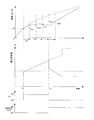
上記制御によるロックアップクラッチ6への差圧指令値と車速VSP、スムースロックアップフラグFlu及び加速不足フラグFαの関係を図3に示す。 FIG. 3 shows the relationship between the differential pressure command value to the lock-up clutch 6 by the above control, the vehicle speed VSP, the smooth lock-up flag Flu, and the underacceleration flag Fα.
車両が発進して車速VSPが上昇し、スムースロックアップON制御の開始条件である所定の車速V1に達する時刻T0では、スムースロックアップフラグFluがONとなり、これに伴って差圧指令値も所定のパターンで上昇してロックアップクラッチ6の締結が開始される。 At time T0 when the vehicle starts and the vehicle speed VSP rises and reaches a predetermined vehicle speed V1, which is a start condition of the smooth lockup ON control, the smooth lockup flag Flu is turned on, and the differential pressure command value is also set accordingly. And the engagement of the lockup clutch 6 is started.
スムースロックアップON制御の開始後は、所定時間ΔT毎にカウンタCntがインクリメントされ、このカウンタCntの値に応じた車速閾値Vss(Cnt)と、現在の車速VSPとの比較が行われ、実際の車速VSPが車速閾値Vss(Cnt)を上回っている限りスムースロックアップON制御が継続する。そして、順調に車速VSPが上昇した場合には、図中破線で示すように車速VSPと差圧指令値が上昇してスムースロックアップが完了する。 After the start of the smooth lockup ON control, the counter Cnt is incremented every predetermined time ΔT, and the vehicle speed threshold Vss (Cnt) corresponding to the value of the counter Cnt is compared with the current vehicle speed VSP, and the actual vehicle speed VSP is compared. As long as the vehicle speed VSP exceeds the vehicle speed threshold Vss (Cnt), the smooth lockup ON control continues. When the vehicle speed VSP increases smoothly, the vehicle speed VSP and the differential pressure command value increase as shown by the broken line in the figure, and the smooth lockup is completed.
一方、急な登り坂での発進などで、車速VSPの伸びが低下した場合は、図中実線で示すように、時刻T1では、スムースロックアップON制御の開始から4回目の車速VSPの監視が行われ、この時点の車速VSPが、車速閾値Vss(4)未満であった場合には、スムースロックアップON制御が中止され、これに代わってスムースロックアップOFF制御が始まる。 On the other hand, if the vehicle speed VSP increases due to a steep uphill start or the like, the vehicle speed VSP is monitored for the fourth time from the start of the smooth lock-up ON control at time T1, as shown by the solid line in the figure. If the vehicle speed VSP at this time is less than the vehicle speed threshold value Vss (4), the smooth lockup ON control is stopped, and instead, the smooth lockup OFF control is started.
この結果、差圧指令値は所定パターンで徐々に低下してロックアップクラッチ6を完全に解放させる。ロックアップクラッチ6の開放に伴ってトルクコンバータ5はコンバータ状態となって入力トルクを増幅するとともにエンジン回転速度Neも上昇するので、登り坂などでの高負荷に応じて車速VSPの伸びを確保して車両の動力性能を維持するとともに、トルクが不足している状況でのロックアップを回避することでこもり音の発生を防止することができる。 As a result, the differential pressure command value gradually decreases in a predetermined pattern, and the lockup clutch 6 is completely released. As the lock-up clutch 6 is released, the torque converter 5 enters a converter state to amplify the input torque and the engine rotational speed Ne also increases, so that the vehicle speed VSP can be increased in response to a high load on an uphill or the like. Thus, while maintaining the power performance of the vehicle, it is possible to prevent the occurrence of a booming noise by avoiding lock-up in a situation where torque is insufficient.
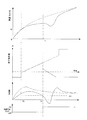
なお、上記においては、所定期間ΔTごとに、車速VSPとスムースロックアップON制御の開始からの経過時間に応じた車速閾値Vss(Cnt)との比較を行って車速VSPの伸びの鈍化を検出したが、図5で示すように、加速度を検出して予め設定した閾値αsを下回ったときに車速VSPの伸びの鈍化を判定し、上記と同様にスムースロックアップON制御を中止してスムースロックアップOFF制御へ移行するようにしても良い。 In the above description, the vehicle speed VSP is compared with the vehicle speed threshold value Vss (Cnt) corresponding to the elapsed time from the start of the smooth lockup ON control for each predetermined period ΔT, and the slowdown in the vehicle speed VSP is detected. However, as shown in FIG. 5, when the acceleration is detected and the vehicle speed VSP is decelerated when the acceleration falls below a preset threshold value αs, the smooth lockup ON control is canceled and the smooth lockup is performed as described above. You may make it transfer to OFF control.
なお、加速の検出は、車速VSPの微分値を用いても良いし、加速センサを設けて加速度を検出しても良い。 For detection of acceleration, a differential value of the vehicle speed VSP may be used, or an acceleration sensor may be provided to detect acceleration.
以上のように、本発明によれば、発進直後の車速の伸びを確保しながら、こもり音の発生を防止できるので、運転性に優れたロックアップクラッチを備えたトルクコンバータを有する自動変速機の制御装置に適用することができる。 As described above, according to the present invention, it is possible to prevent the occurrence of a booming noise while ensuring the increase in the vehicle speed immediately after the start of the vehicle. Therefore, the automatic transmission having the torque converter provided with the lockup clutch having excellent drivability It can be applied to a control device.
1 ATコントローラ
4 自動変速機
5 トルクコンバータ
6 ロックアップクラッチ
1 AT controller 4 Automatic transmission 5 Torque converter 6 Lock-up clutch
Claims (3)
車両の運転状態に基づいて、前記ロックアップクラッチに供給する差圧指令値を演算して、前記トルクコンバータのコンバータ状態とロックアップ状態とをスリップ状態を介して切り換えるロックアップ制御手段と、
車両の発進後に、車速が予め設定した低車速を超えたときには、前記ロックアップ制御手段にロックアップの指令を行う早期ロックアップ指令手段と、
を備えた自動変速機の制御装置において、
前記早期ロックアップ指令手段がロックアップの指令を行った後に、車速の上昇を監視する車速監視手段と、
前記監視した車速の上昇が予め設定した値よりも低下したときには、前記ロックアップ制御手段に対してロックアップの解除を指令してコンバータ状態へ移行させる車速回復手段と、
を備えたことを特徴とする自動変速機の制御装置。 A torque converter interposed between the engine and the automatic transmission and having a lock-up clutch;
Lockup control means for calculating a differential pressure command value to be supplied to the lockup clutch based on a driving state of the vehicle and switching between a converter state and a lockup state of the torque converter via a slip state;
An early lockup command means for instructing the lockup control means to perform a lockup when the vehicle speed exceeds a preset low vehicle speed after starting the vehicle;
In an automatic transmission control device comprising:
Vehicle speed monitoring means for monitoring an increase in vehicle speed after the early lockup command means issues a lockup command;
Vehicle speed recovery means for instructing the lockup control means to release the lockup and shifting to the converter state when the monitored increase in the vehicle speed falls below a preset value;
A control device for an automatic transmission, comprising:
車両の加速度を検出する加速度検出手段を有し、
予め設定した加速度と前記検出した加速度とを比較することを特徴とする請求項1に記載の自動変速機の制御装置。 The vehicle speed monitoring means includes
Having acceleration detection means for detecting the acceleration of the vehicle;
2. The control device for an automatic transmission according to claim 1, wherein a preset acceleration is compared with the detected acceleration.
Priority Applications (2)
| Application Number | Priority Date | Filing Date | Title |
|---|---|---|---|
| JP2004106539A JP4334394B2 (en) | 2004-03-31 | 2004-03-31 | Control device for automatic transmission |
| US11/088,243 US7328095B2 (en) | 2004-03-31 | 2005-03-24 | Lock-up control for torque converter |
Applications Claiming Priority (1)
| Application Number | Priority Date | Filing Date | Title |
|---|---|---|---|
| JP2004106539A JP4334394B2 (en) | 2004-03-31 | 2004-03-31 | Control device for automatic transmission |
Publications (2)
| Publication Number | Publication Date |
|---|---|
| JP2005291346A true JP2005291346A (en) | 2005-10-20 |
| JP4334394B2 JP4334394B2 (en) | 2009-09-30 |
Family
ID=35055446
Family Applications (1)
| Application Number | Title | Priority Date | Filing Date |
|---|---|---|---|
| JP2004106539A Expired - Lifetime JP4334394B2 (en) | 2004-03-31 | 2004-03-31 | Control device for automatic transmission |
Country Status (2)
| Country | Link |
|---|---|
| US (1) | US7328095B2 (en) |
| JP (1) | JP4334394B2 (en) |
Cited By (2)
| Publication number | Priority date | Publication date | Assignee | Title |
|---|---|---|---|---|
| JP2010139004A (en) * | 2008-12-11 | 2010-06-24 | Daihatsu Motor Co Ltd | Lock-up control device |
| JP2012007738A (en) * | 2011-10-04 | 2012-01-12 | Jatco Ltd | Control device for automatic transmission |
Families Citing this family (10)
| Publication number | Priority date | Publication date | Assignee | Title |
|---|---|---|---|---|
| JP4072829B2 (en) | 2004-03-31 | 2008-04-09 | ジヤトコ株式会社 | Control device for automatic transmission |
| JP4116991B2 (en) * | 2004-10-07 | 2008-07-09 | ジヤトコ株式会社 | Control device for automatic transmission |
| GB2447507A (en) * | 2007-03-16 | 2008-09-17 | Cnh Belgium Nv | A method of engaging a clutch in an agricultural machine |
| JP5481023B2 (en) * | 2007-10-25 | 2014-04-23 | 株式会社小松製作所 | Work vehicle and control method of work vehicle |
| JP4920064B2 (en) * | 2009-09-02 | 2012-04-18 | ジヤトコ株式会社 | Control device for automatic transmission |
| JP4951658B2 (en) * | 2009-09-02 | 2012-06-13 | ジヤトコ株式会社 | Control device for automatic transmission |
| JP5788999B2 (en) * | 2012-01-11 | 2015-10-07 | 本田技研工業株式会社 | Control device for lock-up clutch |
| EP2818765A4 (en) * | 2012-02-22 | 2016-12-14 | Toyota Motor Co Ltd | DEVICE FOR CONTROLLING POWER TRANSMISSION APPARATUS |
| US9216741B2 (en) * | 2014-01-14 | 2015-12-22 | Caterpillar Inc. | Lock up clutch controls—high idle set point |
| CN114607507B (en) * | 2022-03-11 | 2023-06-02 | 中国第一汽车股份有限公司 | Engine rotating speed detection method and device, computer equipment and medium |
Family Cites Families (4)
| Publication number | Priority date | Publication date | Assignee | Title |
|---|---|---|---|---|
| JPH03282053A (en) | 1990-03-28 | 1991-12-12 | Mazda Motor Corp | Fastening force control device for fluid coupling |
| JPH05187540A (en) * | 1992-01-09 | 1993-07-27 | Jatco Corp | Lock-up clutch control device |
| JP3402805B2 (en) * | 1994-11-30 | 2003-05-06 | ジヤトコ株式会社 | Lockup control device for automatic transmission |
| JP3743347B2 (en) | 2001-11-12 | 2006-02-08 | 株式会社日立製作所 | Automotive control device |
-
2004
- 2004-03-31 JP JP2004106539A patent/JP4334394B2/en not_active Expired - Lifetime
-
2005
- 2005-03-24 US US11/088,243 patent/US7328095B2/en not_active Expired - Lifetime
Cited By (2)
| Publication number | Priority date | Publication date | Assignee | Title |
|---|---|---|---|---|
| JP2010139004A (en) * | 2008-12-11 | 2010-06-24 | Daihatsu Motor Co Ltd | Lock-up control device |
| JP2012007738A (en) * | 2011-10-04 | 2012-01-12 | Jatco Ltd | Control device for automatic transmission |
Also Published As
| Publication number | Publication date |
|---|---|
| JP4334394B2 (en) | 2009-09-30 |
| US7328095B2 (en) | 2008-02-05 |
| US20050222737A1 (en) | 2005-10-06 |
Similar Documents
| Publication | Publication Date | Title |
|---|---|---|
| KR100740322B1 (en) | Regenerative control apparatus for vehicles equipped with a lock-up clutch | |
| US7769516B2 (en) | Automatic gear control device | |
| JP4133989B2 (en) | Control device for continuously variable transmission | |
| JP4334394B2 (en) | Control device for automatic transmission | |
| US7149616B2 (en) | Control apparatus and method for vehicle | |
| JP3496526B2 (en) | Lockup control device for automatic transmission | |
| JP2011256896A (en) | Automatic transmission | |
| JP4945601B2 (en) | Automatic transmission lockup control device | |
| JP2008069829A (en) | Automatic transmission abnormality determination device | |
| JP4072829B2 (en) | Control device for automatic transmission | |
| US6663533B2 (en) | Lock-up control system for torque converter | |
| JP4116991B2 (en) | Control device for automatic transmission | |
| JP5326684B2 (en) | Control device for vehicle lock-up clutch | |
| US20070225114A1 (en) | Automatic transmission with neutral coast down feature | |
| JP2004353777A (en) | Vehicle idle stop control device | |
| JPH03249475A (en) | Vehicle controller providing automatic transmission | |
| JP2005172078A (en) | Torque converter lockup control device | |
| JP4220207B2 (en) | Rapid deceleration detection device for vehicles | |
| JP2003014101A (en) | Lockup control device for torque converter | |
| KR101941230B1 (en) | Method and apparatus for detecting drive derection of transmission | |
| JPH11311326A (en) | Stall prevention device for automatic transmission | |
| KR100680838B1 (en) | Shift control method and apparatus of continuously variable transmission | |
| JPH05231530A (en) | Control device for vehicle lock-up clutch | |
| KR100391479B1 (en) | Method of controlling lock-up clutch for an continuously variable transmission | |
| JP2004124969A (en) | Lockup control device for automatic transmission |
Legal Events
| Date | Code | Title | Description |
|---|---|---|---|
| A621 | Written request for application examination |
Free format text: JAPANESE INTERMEDIATE CODE: A621 Effective date: 20050818 |
|
| A977 | Report on retrieval |
Free format text: JAPANESE INTERMEDIATE CODE: A971007 Effective date: 20070906 |
|
| A131 | Notification of reasons for refusal |
Free format text: JAPANESE INTERMEDIATE CODE: A131 Effective date: 20070911 |
|
| A521 | Request for written amendment filed |
Free format text: JAPANESE INTERMEDIATE CODE: A523 Effective date: 20071108 |
|
| A02 | Decision of refusal |
Free format text: JAPANESE INTERMEDIATE CODE: A02 Effective date: 20080108 |
|
| A521 | Request for written amendment filed |
Free format text: JAPANESE INTERMEDIATE CODE: A523 Effective date: 20080226 |
|
| A521 | Request for written amendment filed |
Free format text: JAPANESE INTERMEDIATE CODE: A523 Effective date: 20090421 |
|
| A01 | Written decision to grant a patent or to grant a registration (utility model) |
Free format text: JAPANESE INTERMEDIATE CODE: A01 |
|
| A61 | First payment of annual fees (during grant procedure) |
Free format text: JAPANESE INTERMEDIATE CODE: A61 Effective date: 20090623 |
|
| FPAY | Renewal fee payment (event date is renewal date of database) |
Free format text: PAYMENT UNTIL: 20120703 Year of fee payment: 3 |
|
| R150 | Certificate of patent or registration of utility model |
Ref document number: 4334394 Country of ref document: JP Free format text: JAPANESE INTERMEDIATE CODE: R150 Free format text: JAPANESE INTERMEDIATE CODE: R150 |
|
| FPAY | Renewal fee payment (event date is renewal date of database) |
Free format text: PAYMENT UNTIL: 20120703 Year of fee payment: 3 |
|
| FPAY | Renewal fee payment (event date is renewal date of database) |
Free format text: PAYMENT UNTIL: 20130703 Year of fee payment: 4 |
|
| FPAY | Renewal fee payment (event date is renewal date of database) |
Free format text: PAYMENT UNTIL: 20130703 Year of fee payment: 4 |
|
| FPAY | Renewal fee payment (event date is renewal date of database) |
Free format text: PAYMENT UNTIL: 20140703 Year of fee payment: 5 |
|
| R250 | Receipt of annual fees |
Free format text: JAPANESE INTERMEDIATE CODE: R250 |
|
| EXPY | Cancellation because of completion of term |