JP2005291325A - Transmission for vehicle - Google Patents
Transmission for vehicle Download PDFInfo
- Publication number
- JP2005291325A JP2005291325A JP2004105984A JP2004105984A JP2005291325A JP 2005291325 A JP2005291325 A JP 2005291325A JP 2004105984 A JP2004105984 A JP 2004105984A JP 2004105984 A JP2004105984 A JP 2004105984A JP 2005291325 A JP2005291325 A JP 2005291325A
- Authority
- JP
- Japan
- Prior art keywords
- clutch
- air
- shaft
- speed
- vehicle
- Prior art date
- Legal status (The legal status is an assumption and is not a legal conclusion. Google has not performed a legal analysis and makes no representation as to the accuracy of the status listed.)
- Withdrawn
Links
Images
Landscapes
- Control Of Transmission Device (AREA)
Abstract
Description
本発明は、車両用変速機に係り、詳しくは、イナーシャ式のクラッチブレーキを作動させる車両用変速機に関する。 The present invention relates to a vehicle transmission, and more particularly to a vehicle transmission that operates an inertia clutch brake.
車両用変速機(トランスミッション)は、エンジンで発生したトルクを駆動車輪に伝達させる動力伝達装置の一部であり、上記トルクを所定の伝達トルク比に切り換えている。
この車両用変速機のハウジング内には、エンジンからの動力が伝達される入力軸(クラッチ軸)、該入力軸の軸線上にてこの入力軸とは別に配設される出力軸(主軸)、この出力軸と平行に配設されるカウンタ軸(副軸)がそれぞれ備えられている。これら入力軸及びカウンタ軸はクラッチ装置のクラッチディスクとともに回転する軸である。一方、この出力軸は車輪に繋がるプロペラ軸とともに回転する軸である。
A vehicle transmission (transmission) is a part of a power transmission device that transmits torque generated by an engine to drive wheels, and switches the torque to a predetermined transmission torque ratio.
In the housing of the vehicle transmission, an input shaft (clutch shaft) to which power from the engine is transmitted, an output shaft (main shaft) disposed on the axis of the input shaft separately from the input shaft, A counter shaft (secondary shaft) is provided in parallel with the output shaft. These input shaft and counter shaft are shafts that rotate together with the clutch disk of the clutch device. On the other hand, this output shaft is a shaft that rotates together with the propeller shaft connected to the wheels.
また、この車両用変速機には、その変速を自動で行うタイプの他、手動で行うタイプが存在する。当該手動で行うタイプによる車両の発進操作は、運転者の足でクラッチペダルを踏むとともに、その手でギヤチェンジレバーを1速或いはリバースの変速位置にシフトすることから始まる。
換言すれば、車両の発進操作において、上記クラッチペダルが踏まれる直前の時点では、変速位置は1速或いはリバースのいずれにもシフトされていないニュートラルな状態にある。この時点の入力軸はクラッチディスクとともにエンジンのアイドル回転速度で回転し、カウンタ軸及び1速ギヤ、リバースギヤは入力軸に対する歯車比に応じた回転速度で回転しているのに対して、この時点の出力軸は車輪とともに停止している。
In addition, the vehicle transmission includes a type in which the shift is performed automatically in addition to a type in which the shift is performed automatically. The start operation of the vehicle by the manual type starts by stepping on the clutch pedal with the driver's foot and shifting the gear change lever to the first speed or reverse shift position with the hand.
In other words, at the time immediately before the clutch pedal is stepped on in the start operation of the vehicle, the shift position is in a neutral state where it is not shifted to either the first speed or the reverse. The input shaft at this time rotates with the clutch disk at the engine's idle rotation speed, while the counter shaft, the first gear, and the reverse gear rotate at a rotation speed corresponding to the gear ratio with respect to the input shaft. The output shaft of is stopped together with the wheels.
従って、この状態で1速への変速を行うと、入力軸と連動する1速ギヤの回転速度と出力軸の回転速度との速度差が原因となり、一方、リバースへの変速を行うと、入力軸と連動するリバースギヤの回転速度と出力軸の回転速度との速度差が原因となっていずれの場合にもギヤ鳴りが生じることになる。
ここで、トラックやバスの大型車両等の如く2速にシフトして発進させる場合には、別途独立に構成された同期機構が作用するが、この同期機構は1速やリバースの各発進の場合には作用しないのである。
Therefore, if a shift to the first speed is performed in this state, the speed difference between the rotation speed of the first gear that is linked to the input shaft and the rotation speed of the output shaft is a cause. Gear squealing occurs in any case due to the speed difference between the rotational speed of the reverse gear that is linked to the shaft and the rotational speed of the output shaft.
Here, when shifting to the second speed, such as a large vehicle such as a truck or bus, a separate synchronization mechanism acts. This synchronization mechanism is used for each first speed or reverse start. It does not act on.
そこで、この1速やリバースの各発進の場合には出力軸の回転速度との速度差を無くすべく、入力軸及びカウンタ軸並びに1速ギヤ又はリバースギヤを停止させるイナーシャ式のクラッチブレーキ装置が必要になり、この装置を備えた車両用変速機の技術が提案されている(特許文献1)。
ところで、前記従来の技術では、クラッチペダルスイッチ、エンジン回転速度検出スイッチ及び変速位置検出センサからの各出力信号に基づいてディスクを備えたクラッチブレーキ装置の作動制御を行っている。つまり、ECU(電子コントロールユニット)を必須の構成要素とし、このECUには各種の出力信号が入力され、所定の演算を実行した後にブレーキ実行信号を制御バルブ等に出力し、クラッチブレーキの作動タイミング等を制御している。 By the way, in the prior art, the operation control of the clutch brake device provided with the disk is performed based on output signals from the clutch pedal switch, the engine rotation speed detection switch, and the shift position detection sensor. That is, an ECU (electronic control unit) is an indispensable component, and various output signals are input to this ECU. After executing predetermined calculations, a brake execution signal is output to a control valve or the like, and the clutch brake operation timing is determined. Etc. are controlled.
しかしながら、このイナーシャ式のクラッチブレーキ装置は、車両用変速機にオプションで追加される場合が多いものである。すなわち、前記従来の技術では、このクラッチブレーキ装置を後付けするときには、車両用変速機にクラッチブレーキ装置を設ける作業の他、シャシ側において、ECUの設置や上記スイッチ及びセンサとのハーネスの配索等を初めとするブレーキ駆動装置を設ける作業が別途必要になり、これでは、完成車に対する後付け時の改修作業が煩わしくなるとの問題が生ずる。 However, this inertia type clutch brake device is often added as an option to a vehicle transmission. That is, in the conventional technique, when this clutch brake device is retrofitted, in addition to the operation of installing the clutch brake device in the vehicle transmission, on the chassis side, installation of the ECU, wiring of the harness with the switch and sensor, etc. Thus, there is a need for a separate work for providing a brake driving device, which causes a problem that the work for retrofitting a completed vehicle becomes troublesome.
また、このブレーキ駆動装置の構成がクラッチペダルスイッチ、変速位置検出センサ及びECUの如くの電気的な構成では、その配設箇所が点在することになり、その耐久性が低下し得るという問題もある。
本発明は、このような課題に鑑みてなされたもので、クラッチブレーキ装置の改修作業を容易にし、且つ、ブレーキ駆動装置の耐久性を向上させることができる車両用変速機を提供することを目的とする。
In addition, in the case where the configuration of the brake driving device is an electrical configuration such as a clutch pedal switch, a shift position detecting sensor, and an ECU, the arrangement of the brake driving device is scattered, and the durability of the brake driving device may be reduced. is there.
The present invention has been made in view of such a problem, and an object of the present invention is to provide a vehicle transmission that can facilitate the repair work of the clutch brake device and can improve the durability of the brake drive device. And
上記の目的を達成するべく、請求項1記載の車両用変速機は、クラッチ装置に連係し、エンジンからの動力が伝達される入力軸、入力軸に連動してクラッチ装置に連係するカウンタ軸、及び、入力軸とは別に配設され、車輪に連動する出力軸を備えたハウジングと、車両の発進時に、入力軸及び出力軸の各回転速度を同期させる或いはカウンタ軸及び出力軸の各回転速度を同期させるべく、エアを用いてカウンタ軸を制動させるクラッチブレーキ装置と、ハウジング上に載置されているとともに、クラッチ装置からのエアを取り入れ、且つ、車両の変速位置に応じてクラッチブレーキ装置にエアを供給するブレーキ駆動装置とから構成されることを特徴としている。
In order to achieve the above object, a vehicle transmission according to
また、請求項2記載の発明では、クラッチ装置は、クラッチブースタを備え、ブレーキ駆動装置は、クラッチブースタからのエアを取り入れ、その開弁によりクラッチブレーキ装置にエアを供給するエアバルブと、エアバルブの弁体に当接するとともに、変速位置に応じて弁体を押圧してエアバルブを開弁させる開閉タイミング装置とを備えることを特徴としている。 According to a second aspect of the present invention, the clutch device includes a clutch booster, the brake drive device takes in air from the clutch booster, and supplies the air to the clutch brake device by opening the valve, and the valve of the air valve And an opening / closing timing device that opens the air valve by pressing the valve body in accordance with the shift position.
更に、請求項3記載の発明では、ブレーキ駆動装置は、変速位置が1速とリバースとの中間位置から2速と3速との中間位置に至る直前までのセレクト範囲にのみ、クラッチブレーキ装置にエアを供給することを特徴としている。
更にまた、請求項4記載の発明では、ブレーキ駆動装置は、変速位置が1速とリバースとのシフト方向の中間位置にのみ、クラッチブレーキ装置にエアを供給することを特徴としている。
Furthermore, in the invention according to
Furthermore, in the invention described in
従って、請求項1記載の本発明の車両用変速機によれば、ハウジング上にブレーキ駆動装置が設けられており、このブレーキ駆動装置を介してクラッチ装置とクラッチブレーキ装置とを接続すれば、クラッチ装置からのエア及び車両の変速位置に応じてイナーシャ式のクラッチブレーキを作動させることが可能となる。この結果、このクラッチブレーキ装置を車両用変速機にオプションで追加する場合にも、車両用変速機の周辺のみの作業で済ませることができ、クラッチブレーキ装置の改修作業が容易になる。 Therefore, according to the vehicle transmission of the first aspect of the present invention, the brake drive device is provided on the housing, and if the clutch device and the clutch brake device are connected via the brake drive device, the clutch The inertia type clutch brake can be operated according to the air from the apparatus and the shift position of the vehicle. As a result, even when this clutch brake device is added to the vehicle transmission as an option, the work around only the vehicle transmission can be completed, and the clutch brake device can be easily repaired.
また、請求項2記載の発明によれば、ブレーキ駆動装置が機械的な構成となり、クラッチペダルスイッチの他、イナーシャ式のクラッチブレーキを作動制御するECUの構成が不要となる。よって、従来の如くの電気的な構成よりもブレーキ駆動装置の耐久性が向上し、ひいては、車両用変速機の信頼性を高めることができる。
更に、請求項3記載の発明によれば、変速位置が1速とリバースとの中間位置から2速と3速との中間位置に至る直前までのセレクト範囲では、エアバルブの開弁によってクラッチブレーキ装置にエアが供給され、イナーシャ式のクラッチブレーキが作動する。よって、車両の発進時のギヤ鳴りを確実に防止することができる。
According to the second aspect of the present invention, the brake drive device has a mechanical configuration, and the configuration of the ECU for controlling the operation of the inertia clutch brake in addition to the clutch pedal switch is not required. Therefore, the durability of the brake drive device is improved as compared with the conventional electrical configuration, and as a result, the reliability of the vehicle transmission can be improved.
Further, according to the third aspect of the present invention, in the select range from the intermediate position between the first speed and the reverse to the intermediate position between the second speed and the third speed, the clutch brake device is opened by opening the air valve. Air is supplied to the motor and the inertia type clutch brake operates. Therefore, it is possible to reliably prevent gear noise when the vehicle starts.
また、上記セレクト範囲以外の範囲では、イナーシャ式のクラッチブレーキの作動が解除されるので、所望のタイミングにおけるスムーズな変速を維持することができる。
更にまた、請求項4記載の発明によれば、変速位置が1速とリバースとのシフト方向の中間位置にのみ、エアバルブの開弁によってクラッチブレーキ装置にエアが供給される。よって、この場合にも車両の発進時のギヤ鳴りが確実に防止可能となるし、上記シフト方向の中間位置以外の位置では、クラッチブレーキの作動が解除されてスムーズな変速が維持可能となる。
In addition, since the operation of the inertia type clutch brake is released in a range other than the selection range, a smooth shift at a desired timing can be maintained.
Furthermore, according to the fourth aspect of the invention, air is supplied to the clutch brake device by opening the air valve only at the intermediate position in the shift direction between the first speed and the reverse. Therefore, in this case as well, it is possible to reliably prevent gear squeal when starting the vehicle, and at a position other than the intermediate position in the shift direction, the operation of the clutch brake is released and smooth shifting can be maintained.
以下、図面により本発明の実施形態について説明する。
当該図示の車両用変速機2はトラックやバスの大型車両に用いられ、運転手の手でギヤチェンジレバーを1速から7速或いはリバースの所望の変速位置に手動で変更するように構成されている。
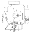
この車両用変速機2はハウジング4を備えている。ハウジング4内には、図示しないエンジンからの動力が伝達される入力軸(クラッチ軸)6が設けられ、この入力軸6は各種の軸受8を介してハウジング4に回転自在に支持されている。
Hereinafter, embodiments of the present invention will be described with reference to the drawings.
The illustrated
The
入力軸6のエンジン側はクラッチ装置のクラッチディスクに連係され、入力軸6はクラッチ装置との接続時にはクラッチディスクとともに回転する。なお、上記クラッチ装置にはクラッチブースタ12が配設されている。また、このクラッチブースタ12にはその倍力エアを受容するエア受容配管38が接続されており、エアはクラッチペダルの踏み込みに応じてエア受容配管38内に導入される。
The engine side of the
このハウジング4内には、入力軸6の軸線上にこの入力軸6とは別に配設される出力軸(主軸)16が設けられ、この出力軸16は軸受18を介してハウジング4に回転自在に支持されている。また、当該出力軸16は図示しない車輪に連動しており、この車輪とともに回転する。なお、出力軸16には、変速位置に応じて軸方向に摺動するスリーブや2速発進用の同期機構がそれぞれ配設されている。
In the
更に、ハウジング4内には、出力軸16に平行に配設され、入力軸6に連動して上記クラッチディスクに連係するカウンタ軸(副軸)20が設けられており、このカウンタ軸20は軸受22を介してハウジング4に回転自在に支持されている。このカウンタ軸20はクラッチ装置との接続時にはクラッチディスクとともに回転する。
本実施形態の車両用変速機2の変速位置は、ギヤチェンジレバーが1速から7速或いはリバースの各変速位置にシフトすることにより決定される。この各変速位置のシフトは、ギヤチェンジレバーが1速とリバースとの中間位置から6速と7速との中間位置までのいずれかのニュートラル状態をセレクトした後に行われる。
Further, a counter shaft (sub shaft) 20 is provided in the
The shift position of the
そして、この変速位置がニュートラル状態から1速から7速のいずれかにシフトされた場合には、トルクは入力軸6からカウンタ軸20を介して出力軸16に間接的に伝達されるように構成され、これに対し、変速位置がニュートラル状態からリバースにシフトされた場合には、トルクはカウンタ軸20及びリバース用アイドラギヤを介して入力軸6から出力軸16に間接的に伝達されるように構成されている。
When the shift position is shifted from the 1st speed to the 7th speed from the neutral state, the torque is indirectly transmitted from the
ここで、車両の発進操作は、まず、運転者の足でクラッチペダルを踏むとともに、その手でギヤチェンジレバーを1速或いはリバースの変速位置にシフトする。次いで、アクセルペダルを徐々に踏みつつ、クラッチペダルを徐々に離すことにより行われる。すなわち、この車両の発進操作において、上記クラッチペダルが踏まれる直前の時点では、変速位置はニュートラルな状態にあり、この時点の入力軸6はクラッチディスクとともにエンジンのアイドル回転速度で回転し、カウンタ軸20及び1速ギヤ、リバースギヤは入力軸6に対する歯車比に応じた回転速度で回転しているのに対し、この時点の出力軸16は車輪とともに停止している。
Here, in the starting operation of the vehicle, first, the driver steps on the clutch pedal and shifts the gear change lever to the first speed or reverse shift position with his / her hand. Next, the clutch pedal is gradually released while gradually depressing the accelerator pedal. That is, in the starting operation of the vehicle, immediately before the clutch pedal is depressed, the speed change position is in a neutral state, and the
従って、このままの状態で1速への変速(シフト)を行うと、1速ギヤの回転速度と出力軸16の回転速度との速度差が原因となり、一方、リバースへの変速(シフト)を行うと、リバースギヤの回転速度と出力軸16の回転速度との速度差が原因となっていずれもギヤ鳴りが生じてしまう。そこで、1速発進或いはリバース発進の場合に発生するギヤ鳴りを防止するクラッチブレーキ装置24が必要になる。
Therefore, if the shift to the first speed is performed in this state, the speed difference between the rotation speed of the first gear and the rotation speed of the
このクラッチブレーキ装置24はハウジング4の側方に配設されており、クラッチブレーキ装置24には、クラッチブースタ12からのエアを受容するケース26が備えられ、このエアはエア取り入れ口28からケース26内に導入される。
また、このケース26内には、カウンタ軸20に連動して回転力を得るシャフト34、エア圧力の増加に応じて図示しないばねの付勢力に抗し、シャフト34に向けて移動するピストン30が配設されている。更に、このピストン30とシャフト34との間にはシャフト34とともに回転するディスク32が配設されており、このディスク32は、ピストン30がシャフト34に向けて移動することにより、アダプタ27に当接される。そして、この場合にはシャフト34の回転が抑制され、カウンタ軸20が制動される。
The
Also, in this
このように、このクラッチブレーキ装置24は、1速或いはリバースへのシフトを行う場合であってクラッチペダルが踏み込まれた直後には、エアを用いてイナーシャ式のクラッチブレーキを作動させ、入力軸6及びカウンタ軸20を制動し、1速ギヤ又はリバースギヤと出力軸16との各回転速度を同期させている。なお、ディスク32とアダプタ27との当接は、ケース26内のエア圧力の減少に伴い、ピストン30が図示しないばねの付勢力によって戻されることにより解除される。
In this way, the
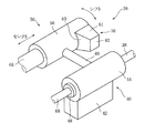
上記クラッチブレーキ装置24はエア伝達装置(ブレーキ駆動装置)36により駆動される。このエア伝達装置36は車両用変速機2のハウジング4上に載置され、また、エア伝達装置36は、エアバルブ40と開閉タイミング装置50とから構成されている。
当該エア伝達装置36の詳細は図2に示されている。
このエアバルブ40には、エア受容配管38を介してクラッチブースタ12からの倍力エアが取り入れられており、このエアはエアバルブ40内に充填されている。そして、エアバルブ40はハウジング4上に固定されるバルブ基部42を備え、このバルブ基部42の上側には弁本体部44が配設されている。この弁本体部44はその内側に図示しない弁体を備えており、この弁体はロッド46の一端に当接され、ロッド46の他端は開閉タイミング装置50に当接され、この弁体はロッド46による押圧力で開弁される。また、弁本体部44には、接続部48を介してエア供給配管68が接続されており、このエア供給配管68はクラッチブレーキ装置24のエア取り入れ口28に接続されている。
The
Details of the
The
一方、開閉タイミング装置50は、ハウジング4上に支持されたシャフト66と回動部56とがスプラインにより嵌合されており、ギヤチェンジレバーが1速とリバースとの中間位置から6速と7速との中間位置までの各ニュートラル状態をセレクトした場合には、矢印で示す如くシャフト66に沿って直線的に移動する。
この回動部56はシャフト66とともに回転するように構成され、変速倍力装置64に接続されている。そして、この回動部56は、ギヤチェンジレバーが各ニュートラル状態から1速から7速或いはリバースのいずれかの変速位置にシフトした場合には、矢印で示す如く回動部56の軸心回りに回動する。
On the other hand, in the opening /
The rotating
また、回動部56の外周部分にはエアバルブ40のロッド46が当接されている。更に、回動部56の外周部分には弁体押圧部58が構成されている。この弁体押圧部58は、回動部56の外周面から外方向に向けて突出されており、変速倍力装置64側に向かう法線を有しエアバルブ40に対して斜面で対向する押圧斜面部60と、エアバルブ40に対して正面で対向する押圧正面部62と、押圧斜面部60及び押圧正面部62の両側で回動部56の外周面に連なる押圧側面部61とから構成されている。
Further, the
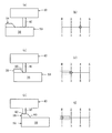
上記エア伝達装置36の動作については、図3及び図4に示されている。
運転者の足によってクラッチペダルが踏み込まれ、ギヤチェンジレバーによるシフトが解除されると、変速位置はニュートラル状態となる。ここで、変速位置が6速と7速との中間位置や4速と5速との中間位置(図3(b))にセレクトされている場合には、回動部56は、エアバルブ40のロッド46が回動部56の外周面に当接されており(図3(a))、弁体押圧部58によって押圧されていない。よって、この場合には、エアバルブ40の弁体が開弁せず、エア伝達装置36がエアの供給駆動を行わないことから、クラッチブレーキ装置24は作動されない。この結果、入力軸6及びカウンタ軸20は制動されない。
The operation of the
When the clutch pedal is depressed by the driver's foot and the shift by the gear change lever is released, the shift position becomes neutral. Here, when the shift position is selected to be an intermediate position between the 6th speed and the 7th speed or an intermediate position between the 4th speed and the 5th speed (FIG. 3B), the rotating
また、変速位置が2速と3速との中間位置(図3(d))にセレクトされた場合にも、回動部56は、ロッド46が回動部56の外周面に当接されており(図3(c))、弁体押圧部58によって押圧されていない。よって、この場合にも、エア伝達装置36がエアの供給駆動を行わず、入力軸6及びカウンタ軸20は制動されない。
これに対し、変速位置が、図3(f)にて鎖線で囲まれるように、1速とリバースとの中間位置から2速と3速との中間位置に至る直前までの各ニュートラル状態(1−R範囲)にセレクトした場合には、入力軸6及びカウンタ軸20は制動されることになる。
In addition, even when the shift position is selected to be an intermediate position between the second speed and the third speed (FIG. 3D), the rotating
On the other hand, each neutral state (1) from the middle position between the first speed and the reverse to the middle position between the second speed and the third speed, as indicated by the chain line in FIG. -R range), the
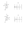
具体的には、変速位置が2速と3速との中間位置から1速とリバースとの中間位置に向けてセレクトされると、エアバルブ40のロッド46が押圧斜面部60に当接し、この押圧斜面部60上に乗り上げると、ロッド46はセレクト回動部56の外周面から離れ、エアバルブ40の弁体を押圧し始める。次いで、変速位置が1速とリバースとの中間位置(図3(f)、図4(b))にセレクトされている場合には、ロッド46は押圧正面部62に当接し、ロッド46はエアバルブ40の弁体をより一層押圧する(図3(e)、図4(a))。
Specifically, when the shift position is selected from an intermediate position between the second speed and the third speed to an intermediate position between the first speed and the reverse, the
そして、エアバルブ40の弁体が開弁すると、エア伝達装置36がクラッチブースタ12からのエアをクラッチブレーキ装置24に供給すべく駆動する。この結果、エアを受容したクラッチブレーキ装置24が作動され、入力軸6及びカウンタ軸20が制動される。
このように、運転者の足がクラッチペダルを踏み込み、その手がギヤチェンジレバーを上記1−R範囲内の変速位置にシフトさせると、イナーシャ式のクラッチブレーキによって入力軸6及びカウンタ軸20が停止される。しかしながら、図4(d)に示されるように、変速位置が1速とリバースとのシフト方向の中間位置から1速にシフトされた場合には、エアバルブ40のロッド46は、押圧側面部61を経由して回動部56の外周面に当接され、エアバルブ40の弁体が閉弁する。よって、入力軸6及びカウンタ軸20は制動されないことになる。なお、リバースにシフトされた場合にも同様にクラッチブレーキが解除される。
When the valve body of the
Thus, when the driver's foot depresses the clutch pedal and the hand shifts the gear change lever to the shift position within the 1-R range, the
以上のように、本実施形態では、ハウジング4上にエア伝達装置36を設けており、このエア伝達装置36を介してクラッチブースタ12とクラッチブレーキ装置24と接続すれば、クラッチブースタ12からの倍力エアと変速位置に応じてイナーシャ式のクラッチブレーキを作動させることが可能となる。従って、このクラッチブレーキ装置24を車両用変速機2にオプションで追加する場合にも、車両用変速機2上の部品交換の作業で総ての作業を済ませることができ、シャシ側の改修作業を無くし、クラッチブレーキ装置24の改修作業が容易になる。
As described above, in the present embodiment, the
また、エア伝達装置36が機械的な構成となり、クラッチペダルスイッチの他、イナーシャ式のクラッチブレーキの作動を制御するECUの構成も不要となる。また、クラッチブレーキを駆動させるためのスピードセンサやマグネットバルブの構成も不要となる。よって、従来の如くの電気的な構成に比してエア伝達装置36の耐久性が向上する。これは車両用変速機2の信頼性を高めることに寄与できる。
Further, the
更に、変速位置が上記1−R範囲の場合には、エアバルブ40の開弁によってクラッチブレーキ装置24にエアを供給され、イナーシャ式のクラッチブレーキが作動するので、車両の発進時のギヤ鳴りは確実に防止される。
しかも、上記1−R範囲以外の範囲や各シフト位置では、このクラッチブレーキが解除される。よって、カウンタ軸20がいつまでも制動し続けることが防止され、所望のタイミングにおけるスムーズな変速が維持可能となる。
Further, when the gear shift position is in the 1-R range, air is supplied to the
In addition, the clutch brake is released in ranges other than the 1-R range and shift positions. Therefore, the
以上で本発明の一実施形態についての説明を終えるが、本発明は上記実施形態に限定されるものではなく、本発明の趣旨を逸脱しない範囲で種々の変更ができるものである。
例えば、上記実施形態の1速発進では、トルクは入力軸6からカウンタ軸20を介して出力軸16に間接的に伝達され、リバース発進では、トルクはカウンタ軸20及びリバース用アイドラギヤを介して入力軸6から出力軸16に間接的に伝達される構成が示されているが、必ずしもこの形態に限定されるものではなく、一例を挙げれば、いずれの発進についても、トルクは入力軸6から出力軸16に直接的に伝達されていても良い。この場合にも上述と同様に、クラッチブレーキ装置24の改修作業の容易化やエア伝達装置36の耐久性の向上化を達成できる。
The description of one embodiment of the present invention is finished above, but the present invention is not limited to the above-described embodiment, and various modifications can be made without departing from the spirit of the present invention.
For example, in the first speed start of the above embodiment, torque is indirectly transmitted from the
2 車両用変速機
4 ハウジング
6 入力軸(クラッチ軸)
12 クラッチブースタ
16 出力軸(主軸)
20 カウンタ軸(副軸)
24 クラッチブレーキ装置
36 エア伝達装置(ブレーキ駆動装置)
40 エアバルブ
50 開閉タイミング装置
2
12
20 Counter axis (sub axis)
24
40
Claims (4)
車両の発進時に、前記入力軸及び前記出力軸の各回転速度を同期させる或いは前記カウンタ軸及び前記出力軸の各回転速度を同期させるべく、エアを用いて前記カウンタ軸を制動させるクラッチブレーキ装置と、
前記ハウジング上に載置されているとともに、前記クラッチ装置からのエアを取り入れ、且つ、前記車両の変速位置に応じて前記クラッチブレーキ装置に前記エアを供給するブレーキ駆動装置と、
から構成されることを特徴とする車両用変速機。 An input shaft linked to the clutch device, to which power from the engine is transmitted, a counter shaft linked to the clutch device linked to the input shaft, and an output linked to the wheels and arranged separately from the input shaft A housing with a shaft;
A clutch brake device that brakes the counter shaft using air to synchronize the rotational speeds of the input shaft and the output shaft or synchronize the rotational speeds of the counter shaft and the output shaft when the vehicle starts. ,
A brake drive device mounted on the housing, taking in air from the clutch device, and supplying the air to the clutch brake device according to a shift position of the vehicle;
A transmission for a vehicle comprising:
前記ブレーキ駆動装置は、該クラッチブースタからのエアを取り入れ、その開弁により前記クラッチブレーキ装置に前記エアを供給するエアバルブと、該エアバルブの弁体に当接するとともに、前記変速位置に応じて該弁体を押圧して前記エアバルブを開弁させる開閉タイミング装置と、
を備えることを特徴とする請求項1に記載の車両用変速機。 The clutch device includes a clutch booster,
The brake driving device takes in air from the clutch booster, contacts the valve body of the air valve with an air valve that supplies the air to the clutch brake device by opening the valve, and the valve according to the shift position. An opening and closing timing device that presses the body to open the air valve;
The vehicle transmission according to claim 1, further comprising:
Priority Applications (1)
| Application Number | Priority Date | Filing Date | Title |
|---|---|---|---|
| JP2004105984A JP2005291325A (en) | 2004-03-31 | 2004-03-31 | Transmission for vehicle |
Applications Claiming Priority (1)
| Application Number | Priority Date | Filing Date | Title |
|---|---|---|---|
| JP2004105984A JP2005291325A (en) | 2004-03-31 | 2004-03-31 | Transmission for vehicle |
Publications (1)
| Publication Number | Publication Date |
|---|---|
| JP2005291325A true JP2005291325A (en) | 2005-10-20 |
Family
ID=35324488
Family Applications (1)
| Application Number | Title | Priority Date | Filing Date |
|---|---|---|---|
| JP2004105984A Withdrawn JP2005291325A (en) | 2004-03-31 | 2004-03-31 | Transmission for vehicle |
Country Status (1)
| Country | Link |
|---|---|
| JP (1) | JP2005291325A (en) |
Cited By (1)
| Publication number | Priority date | Publication date | Assignee | Title |
|---|---|---|---|---|
| KR100828682B1 (en) | 2006-09-21 | 2008-05-09 | 현대자동차주식회사 | Counter Shaft Brake Device of Transmission |
-
2004
- 2004-03-31 JP JP2004105984A patent/JP2005291325A/en not_active Withdrawn
Cited By (1)
| Publication number | Priority date | Publication date | Assignee | Title |
|---|---|---|---|---|
| KR100828682B1 (en) | 2006-09-21 | 2008-05-09 | 현대자동차주식회사 | Counter Shaft Brake Device of Transmission |
Similar Documents
| Publication | Publication Date | Title |
|---|---|---|
| CN101341054B (en) | Parking control system for vehicle | |
| CN111197651B (en) | Shifting device for multi-speed transmission for electric vehicle | |
| JP3270933B2 (en) | Control device and method for executing selective shift | |
| JP5731884B2 (en) | Vehicle power transmission control device | |
| ITMI990301A1 (en) | GEAR CHANGE SYSTEM ELECTRONICALLY CONTROLLED FOR A MANUAL TRANSMISSION | |
| JPH0791537A (en) | Electronically controlled transmission | |
| US6856880B2 (en) | Automatic shift controller for a vehicle | |
| US6258009B1 (en) | Method for controlling a multiple speed axle shifting apparatus | |
| JP4667078B2 (en) | Vehicle drive device | |
| JP3838422B2 (en) | Shift control device and method for automatic transmission for vehicle | |
| JP5102786B2 (en) | Method and apparatus for controlling a disk clutch | |
| JP2010065731A (en) | Learning control device for automatic clutch | |
| JP2010101460A (en) | Backward movement preventing device for transmission | |
| US5980413A (en) | Electronic controller for a multiple speed axle shifting apparatus | |
| US6154700A (en) | Integrated transmission and multiple speed axle shifting apparatus | |
| JP2005291325A (en) | Transmission for vehicle | |
| US7611003B2 (en) | Apparatus for braking counter shaft of transmission | |
| JP2002349699A (en) | Gear speed changer for vehicle transmission | |
| KR100264567B1 (en) | Automotive half clutch system | |
| JP2019007512A (en) | Manual transmission for vehicle | |
| KR960000178Y1 (en) | Automatic transmission device of gasoline-saving car | |
| JPH0287040A (en) | Testing apparatus for transmission for automobile | |
| KR0126079B1 (en) | Non-clutch motor | |
| KR100410900B1 (en) | Clutch system for motor vehicle | |
| JP3398431B2 (en) | Electronically controlled transmission |
Legal Events
| Date | Code | Title | Description |
|---|---|---|---|
| A621 | Written request for application examination |
Effective date: 20061227 Free format text: JAPANESE INTERMEDIATE CODE: A621 |
|
| A761 | Written withdrawal of application |
Free format text: JAPANESE INTERMEDIATE CODE: A761 Effective date: 20070806 |