JP2005291302A - Hydraulic shock absorber - Google Patents
Hydraulic shock absorber Download PDFInfo
- Publication number
- JP2005291302A JP2005291302A JP2004105185A JP2004105185A JP2005291302A JP 2005291302 A JP2005291302 A JP 2005291302A JP 2004105185 A JP2004105185 A JP 2004105185A JP 2004105185 A JP2004105185 A JP 2004105185A JP 2005291302 A JP2005291302 A JP 2005291302A
- Authority
- JP
- Japan
- Prior art keywords
- cylinder
- spring seat
- shock absorber
- hydraulic shock
- piston
- Prior art date
- Legal status (The legal status is an assumption and is not a legal conclusion. Google has not performed a legal analysis and makes no representation as to the accuracy of the status listed.)
- Abandoned
Links
Images

Classifications
-
- F—MECHANICAL ENGINEERING; LIGHTING; HEATING; WEAPONS; BLASTING
- F16—ENGINEERING ELEMENTS AND UNITS; GENERAL MEASURES FOR PRODUCING AND MAINTAINING EFFECTIVE FUNCTIONING OF MACHINES OR INSTALLATIONS; THERMAL INSULATION IN GENERAL
- F16F—SPRINGS; SHOCK-ABSORBERS; MEANS FOR DAMPING VIBRATION
- F16F9/00—Springs, vibration-dampers, shock-absorbers, or similarly-constructed movement-dampers using a fluid or the equivalent as damping medium
- F16F9/32—Details
- F16F9/3207—Constructional features
- F16F9/3235—Constructional features of cylinders
-
- B—PERFORMING OPERATIONS; TRANSPORTING
- B60—VEHICLES IN GENERAL
- B60G—VEHICLE SUSPENSION ARRANGEMENTS
- B60G15/00—Resilient suspensions characterised by arrangement, location or type of combined spring and vibration damper, e.g. telescopic type
- B60G15/02—Resilient suspensions characterised by arrangement, location or type of combined spring and vibration damper, e.g. telescopic type having mechanical spring
- B60G15/06—Resilient suspensions characterised by arrangement, location or type of combined spring and vibration damper, e.g. telescopic type having mechanical spring and fluid damper
- B60G15/062—Resilient suspensions characterised by arrangement, location or type of combined spring and vibration damper, e.g. telescopic type having mechanical spring and fluid damper the spring being arranged around the damper
- B60G15/063—Resilient suspensions characterised by arrangement, location or type of combined spring and vibration damper, e.g. telescopic type having mechanical spring and fluid damper the spring being arranged around the damper characterised by the mounting of the spring on the damper
-
- B—PERFORMING OPERATIONS; TRANSPORTING
- B60—VEHICLES IN GENERAL
- B60G—VEHICLE SUSPENSION ARRANGEMENTS
- B60G2202/00—Indexing codes relating to the type of spring, damper or actuator
- B60G2202/30—Spring/Damper and/or actuator Units
- B60G2202/31—Spring/Damper and/or actuator Units with the spring arranged around the damper, e.g. MacPherson strut
- B60G2202/312—The spring being a wound spring
-
- B—PERFORMING OPERATIONS; TRANSPORTING
- B60—VEHICLES IN GENERAL
- B60G—VEHICLE SUSPENSION ARRANGEMENTS
- B60G2204/00—Indexing codes related to suspensions per se or to auxiliary parts
- B60G2204/10—Mounting of suspension elements
- B60G2204/12—Mounting of springs or dampers
- B60G2204/124—Mounting of coil springs
- B60G2204/1242—Mounting of coil springs on a damper, e.g. MacPerson strut
-
- B—PERFORMING OPERATIONS; TRANSPORTING
- B60—VEHICLES IN GENERAL
- B60G—VEHICLE SUSPENSION ARRANGEMENTS
- B60G2204/00—Indexing codes related to suspensions per se or to auxiliary parts
- B60G2204/40—Auxiliary suspension parts; Adjustment of suspensions
- B60G2204/44—Centering or positioning means
-
- B—PERFORMING OPERATIONS; TRANSPORTING
- B60—VEHICLES IN GENERAL
- B60G—VEHICLE SUSPENSION ARRANGEMENTS
- B60G2206/00—Indexing codes related to the manufacturing of suspensions: constructional features, the materials used, procedures or tools
- B60G2206/01—Constructional features of suspension elements, e.g. arms, dampers, springs
- B60G2206/80—Manufacturing procedures
- B60G2206/82—Joining
- B60G2206/8209—Joining by deformation
-
- B—PERFORMING OPERATIONS; TRANSPORTING
- B60—VEHICLES IN GENERAL
- B60G—VEHICLE SUSPENSION ARRANGEMENTS
- B60G2206/00—Indexing codes related to the manufacturing of suspensions: constructional features, the materials used, procedures or tools
- B60G2206/01—Constructional features of suspension elements, e.g. arms, dampers, springs
- B60G2206/90—Maintenance
- B60G2206/91—Assembly procedures
Landscapes
- Engineering & Computer Science (AREA)
- Mechanical Engineering (AREA)
- General Engineering & Computer Science (AREA)
- Fluid-Damping Devices (AREA)
Abstract
Description
本発明は、スプリングシートが装着された油圧緩衝器に関するものである。 The present invention relates to a hydraulic shock absorber provided with a spring seat.
自動車のサスペンション装置に装着される油圧緩衝器には、シリンダ部の外周部に、サスペンションスプリングを受けるためのスプリングシートが装着されたものがある。従来、この種の油圧緩衝器では、スプリングシートは、シリンダ部の外周部に直接溶接されて固定されていた。しかしながら、スプリングシートをシリンダ部に直接溶接した場合、溶接時に生じるコンタミネーション及び熱によるシリンダ部の変形の問題がある。特に、単筒式油圧緩衝器の場合、ピストンが摺動するシリンダの外周部に、スプリングシートが直接溶接されることになるため、これらの影響が大きく、問題となる。 Some hydraulic shock absorbers mounted on a suspension device of an automobile are provided with a spring seat for receiving a suspension spring on an outer peripheral portion of a cylinder portion. Conventionally, in this type of hydraulic shock absorber, the spring seat is directly welded and fixed to the outer peripheral portion of the cylinder portion. However, when the spring seat is directly welded to the cylinder portion, there is a problem of contamination that occurs during welding and deformation of the cylinder portion due to heat. In particular, in the case of a single cylinder type hydraulic shock absorber, the spring seat is directly welded to the outer peripheral portion of the cylinder on which the piston slides.
そこで、特許文献1に記載されたものでは、スプリングシートを略釣鐘状に形成し、これをシリンダ部の外周に圧入し、ピストンロッド突出端に当接させることによって固定するようにしている。また、特許文献2に記載されたものでは、スプリングシートに開口部を形成し、シリンダ部の外周部に凸部を形成し、これらの回転、係合によって、スプリングシートをシリンダ部に固定するようにしている。これにより、スプリングシートを溶接することなくシリンダ部に固定することができる。
しかしながら、上記特許文献1及び2に記載されたものでは、次のような問題がある。特許文献1に記載されたものでは、スプリングシートは、シリンダ部のロッド突出端からスプリングを受けるばね受部まで延びる形状となるため、部品寸法及び重量が大きくなる。また、特許文献2に記載されたものでは、係合用の凸部及び開口部の形状が複雑であるため、加工が煩雑であり、また、単筒式油圧緩衝器に適用した場合には、シリンダの変形が問題となる。
However, those described in
本発明は、上記の点に鑑みてなされたものであり、スプリングシートをシリンダ部に取付ける際、溶接を不要とし、かつ、シリンダ部の変形を最小限に抑えるようにした油圧緩衝器を提供することを目的とする。 The present invention has been made in view of the above points, and provides a hydraulic shock absorber that eliminates the need for welding and minimizes deformation of the cylinder portion when the spring seat is attached to the cylinder portion. For the purpose.
上記の課題を解決するために、請求項1の発明に係る油圧緩衝器は、ピストンロッドが突出するシリンダ部の外周に、周方向に沿って1つ又は複数の凸部を形成し、該凸部の頂部に、環状のスプリングシートを圧入したことを特徴とする。
請求項2の発明に係る油圧緩衝器は、上記請求項1の構成において、前記シリンダ部は、ピストン及びフリーピストンが摺動可能に嵌装される単筒式油圧緩衝器のシリンダであり、前記凸部は、前記ピストン及びフリーピストンの非摺動領域に配置されていることを特徴とする。
請求項3の発明に係る油圧緩衝器は、上記請求項1又は2の構成において、前記複数の凸部は、前記シリンダの軸方向に沿って2列以上配置されていることを特徴とする。
請求項4の発明に係る油圧緩衝器は、上記請求項3の構成において、前記軸方向に沿って配置された凸部の間における前記シリンダの内径は、該シリンダのピストン摺動領域の内径よりも大きいことを特徴とする。
請求項5の発明に係る油圧緩衝器は、上記請求項1乃至4のいずれかの構成において、前記スプリングシートの最小内径は、前記シリンダ部の外径よりも大きいことを特徴とする。
In order to solve the above-mentioned problem, the hydraulic shock absorber according to the invention of claim 1 is configured such that one or a plurality of convex portions are formed along the circumferential direction on the outer periphery of the cylinder portion from which the piston rod protrudes. An annular spring seat is press-fitted into the top of the part.
The hydraulic shock absorber according to the invention of
A hydraulic shock absorber according to a third aspect of the invention is characterized in that, in the configuration of the first or second aspect, the plurality of convex portions are arranged in two or more rows along the axial direction of the cylinder.
According to a fourth aspect of the present invention, in the hydraulic shock absorber according to the third aspect, the inner diameter of the cylinder between the convex portions arranged along the axial direction is greater than the inner diameter of the piston sliding region of the cylinder. Is also large.
A hydraulic shock absorber according to a fifth aspect of the present invention is characterized in that, in the configuration of any of the first to fourth aspects, a minimum inner diameter of the spring seat is larger than an outer diameter of the cylinder portion.
請求項1の発明に係る油圧緩衝器によれば、1つ又は複数の凸部の頂部との圧入によってスプリングシートをシリンダ部に固定することができ、溶接及びシリンダ部の変形の問題を解消することができる。
請求項2の発明に係る油圧緩衝器によれば、凸部によってピストン及びフリーピストンのシール性を損なうことがない。
請求項3の発明に係る油圧緩衝器によれば、2列以上配置された凸部によって、スプリングシートに作用するモーメント荷重を効果的に支持することができる。
請求項4の発明に係る油圧緩衝器によれば、ピストンをシリンダ内に嵌装する最、ピストのシール部が損傷しにくくなる。
請求項5の発明に係る油圧緩衝器によれば、スプリングシートを圧入する際、スプリングシートがシリンダ部の外周部に干渉することがなく、シリンダ部の表面を損傷することがない。
According to the hydraulic shock absorber according to the first aspect of the present invention, the spring seat can be fixed to the cylinder portion by press-fitting with the top of one or a plurality of convex portions, and the problems of welding and deformation of the cylinder portion are eliminated. be able to.
According to the hydraulic shock absorber pertaining to the invention of
According to the hydraulic shock absorber pertaining to the invention of claim 3, the moment load acting on the spring seat can be effectively supported by the convex portions arranged in two or more rows.
According to the hydraulic shock absorber according to the fourth aspect of the present invention, when the piston is fitted in the cylinder, the seal portion of the piston is hardly damaged.
According to the hydraulic shock absorber pertaining to the fifth aspect of the present invention, when the spring seat is press-fitted, the spring seat does not interfere with the outer peripheral portion of the cylinder portion, and the surface of the cylinder portion is not damaged.
以下、本発明の一実施形態を図面に基づいて詳細に説明する。
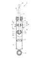
図1及び図2に示すように、本実施形態に係る油圧緩衝器1は、単筒式油圧緩衝器であり、有底円筒状のシリンダ2(シリンダ部)の開口部にロッドガイド3およびオイルシール4が取付けられ、シリンダ2内の底部側に、フリーピストン5が摺動可能に嵌装されている。シリンダ2内は、フリーピストン5によって底部側のガス室6と他端側の油室7とに画成されており、ガス室6には高圧ガスが封入され、油室7には油液が封入されている。
Hereinafter, an embodiment of the present invention will be described in detail with reference to the drawings.
As shown in FIGS. 1 and 2, the hydraulic shock absorber 1 according to the present embodiment is a single cylinder type hydraulic shock absorber, and a rod guide 3 and oil are provided in an opening portion of a bottomed cylindrical cylinder 2 (cylinder portion). A
シリンダ2の油室7には、ピストン8が摺動可能に嵌装され、このピストン8によって、油室7内がシリンダ上室7Aとシリンダ下室7Bとの2室に画成されている。ピストン8には、ピストンロッド9の一端がナット10によって連結されており、ピストンロッド9の他端側は、ロッドガイド3およびオイルシール4に摺動可能かつ液密的に挿通されて外部へ延出されている。
A
ピストン8には、シリンダ上下室7A,7B間を連通させる伸び側油路11および縮み側油路12が設けられている。伸び側油路11および縮み側油路12には、それぞれ、その油液の流動を制御して減衰力を発生させるオリフィスおよびディスクバルブ等からなる伸び側減衰力発生機構13および縮み側減衰力発生機構14が設けられている。
The
この構成により、ピストンロッド9の伸び行程時には、シリンダ2内のピストン8の摺動にともない、シリンダ上室7Aの油液がピストン8の伸び側油路11を通ってシリンダ下室7Bへ流れ、伸び側減衰力発生機構13によって減衰力が発生する。また、縮み行程時には、シリンダ下室7Bの油液が縮み側油路13を通ってシリンダ上室7Aへ流れ、縮み側減衰力発生機構14によって減衰力が発生する。このとき、ピストンロッド9の侵入、退出による油室7の容積変化をフリーピストン5が移動してガス室6の高圧ガスを圧縮、膨張することによって補償する。
With this configuration, during the extension stroke of the
シリンダ2の底部には、サスペンションアーム等(図示せず)に連結するための取付アイ15が結合されており、ピストンロッド9の先端部には、車体側に連結するための取付部16が設けられている。シリンダ2の上端側外周部には、車体との間に介装されるサスペンションスプリング(図示せず)を受けるためのスプリングシート17が取付けられている。ピストンロッド9には、シリンダ2の内部にリバウンドストッパ18が取付けられている。
A mounting
次に、スプリングシート17のシリンダ2への取付構造について説明する。
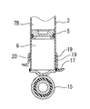
油圧緩衝器1では、ピストンロッド9は、リバウンドストッパ18によって伸び側のストロークが制限されており、これにより、シリンダ2内におけるピストン8の摺動領域が制限されて、シリンダ2の上部にピストン8の非摺動領域Aが存在する。
Next, a structure for attaching the
In the hydraulic shock absorber 1, the stroke of the
シリンダ2には、非摺動領域Aに、周方向に沿って複数の凸部19が形成されている。凸部19は、シリンダ2の周方向に沿って4個形成され、これらがシリンダ2の軸方向に沿って所定の間隔をもって2列配置されている。軸方向に沿って2列配置された凸部19の間におけるシリンダ2の内径は、ピストン8の摺動領域の内径よりも大きくなっている(図2中の寸法D参照)。一方、スプリングシート17は、上端部が縮径されて、大径部20及び小径部21が形成され、これらの間に段部22が形成されている。そして、シリンダ2の凸部19の頂部がスプリングシートの大径部20に圧入され、上側の凸部19が段部22に当接して、スプリングシート17がシリンダ2に固定されている。このように、凸部19と大径部20とが圧入嵌めとなっているのに対して、シリンダ2の外周部とスプリングシート17の最小内径を有する小径部21とは、隙間嵌めとなっており、これらの間に隙間Cが形成されている。凸部19の頂部側の角部及びスプリングシート17の段部22の角部は、これらの乗り越し荷重を高めるために、充分に角だしサイジングされている。
In the
以上のように構成した本実施形態の作用について、次に説明する。
スプリングシート17は、その大径部20にシリンダ2の凸部19の頂部が圧入されて、段部22に凸部19が当接することによって、シリンダ2に固定されている。凸部19は、非摺動領域Aに配置されているので、ピストン8のシール性を損なうことがない。凸部19は、シリンダ2の周方向に沿って複数設けられているので、これがシリンダ2の全周にわたって設けられ場合に比して、凸部19を塑性加工する際のシリンダ2の歪が少なくなっている。このため、ピストン8がシリンダ2の内部を直接摺動する単筒式の油圧緩衝器においても、シリンダ2の変形によるシール性の低下の問題を生じない。凸部19は、軸方向に沿って所定の間隔をもって2列配置されているので、スプリンシート17にかかるモーメント荷重を効率的に支持することができる。軸方向に2列配置された凸部19の間におけるシリンダ2の内径は、ピストンの摺動領域の内径よりも寸法Dだけ大きくなっているので、フリーピストン5及びピストン8をシリンダ2内に嵌装する際、これらのシール部が損傷しにくい。互いに当接する凸部19及び段部22の角部を充分に角だしサイジングすることにより、これらの乗り越し荷重を大きくすることができ、スプリングシート17の軸方向の取付強度を高めることができる。スプリングシート17の小径部21とシリンダ2の外周部とは、隙間嵌めとなっており、これらの間に隙間Cが形成されるので、スプリングシート17をシリンダ2に圧入する際、小径部21がシリンダ2の外周面に干渉することがなく、シリンダ2の塗装面を傷付けることがない。
Next, the operation of the present embodiment configured as described above will be described.
The
なお、上記実施形態では、凸部19をシリンダ2の周方向に沿って4個、軸方向に沿って2列配置した場合について説明しているが、凸部19は、このほか、周方向に2個以上、軸方向に3列以上設けることができ、また、頂部の軸方向の寸法を大きくすることにより、1列であっても、スプリングシート17にかかるモーメント荷重を支持することができる。スプリングシート17は、シリンダ2のピストン8及びフリーピストン5の非摺動領域に凸部19を配置すれば、他の部位に取付けることができ、例えば図3に示すように、シリンダ2の底部付近に取付けることもできる。また、上記実施形態では、スプリングシート17を単筒式の油圧緩衝器1のシリンダ2に取付ける場合について説明しているが、スプリングシート17は、シリンダ部の外周部に凸部19を形成することにより、シリンダの外周に外筒を有する複筒式の油圧緩衝器、サスペンションストラット等にも同様に取付けることができる。
In addition, although the said embodiment demonstrated the case where the four
次に、スプリングシート17のシリンダ2への取付工程について、図4及び図5を参照して説明する。
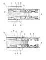
図4(A)に示すように、シリンダ2に凸部19を形成するための加工装置23は、シリンダ2内に挿入されて、凸部19を押出す凸状のポンチ部24を有する加圧ピース25(内型)と、加圧ピース25間に挿入される楔状のマンドレル26と、シリンダ2内で加圧ピース25を径方向に移動可能に支持する加圧ピース保持器27及び加圧ピースガイド28と、加圧ピース25及びマンドレル26を初期位置に復帰するためのリターンスプリング29と、シリンダ2に外嵌されて、加圧ピース25のポンチ部24によって押出された凸部19を所定の形状に角だしサイジングする凹状のダイス部30を有する分割式の外型31とを備えている。
Next, the process of attaching the
As shown in FIG. 4A, the
そして、図4(B)に示すように、加圧ピース27及び外型31を位置決めし、加圧ピース25間にマンドレル26を挿入して、加圧ピース25を径方向外側へ移動、拡開させ、ポンチ部24によってシリンダ2の側壁を外型31のダイス部30へ押込むようにせん断変形させて凸部19を成形する。このようにして、加圧ピース27のポンチ部24と外型31のダイス部30によって、凸部19の変形を拘束することにより、高い精度で角だしサイジングすることができる。凸部19を成形した後、リターンスプリング29によってマンドレル26及び加圧ピース25を後退させ、外型31を開いて、凸部19が形成されたシリンダ2を取出す。
4B, the
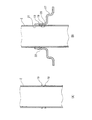
そして、図5(A)に示すように、凸部19が形成されたシリンダ2に、図5(B)に示すように、スプリングシート17を圧入する。
Then, as shown in FIG. 5A, the
1 油圧緩衝器、2 シリンダ(シリンダ部)、5 フリーピストン、8 ピストン、9 ピストンロッド、17 スプリングシート、19 凸部、A 非摺動領域
1 Hydraulic shock absorber, 2 cylinder (cylinder part), 5 free piston, 8 piston, 9 piston rod, 17 spring seat, 19 convex part, A non-sliding area
Claims (5)
The hydraulic shock absorber according to any one of claims 1 to 4, wherein a minimum inner diameter of the spring seat is larger than an outer diameter of the cylinder portion.
Priority Applications (3)
| Application Number | Priority Date | Filing Date | Title |
|---|---|---|---|
| JP2004105185A JP2005291302A (en) | 2004-03-31 | 2004-03-31 | Hydraulic shock absorber |
| CN200510054892.4A CN1676967A (en) | 2004-03-31 | 2005-03-22 | Oil buffer |
| US11/090,056 US20050218574A1 (en) | 2004-03-31 | 2005-03-28 | Hydraulic shock absorber |
Applications Claiming Priority (1)
| Application Number | Priority Date | Filing Date | Title |
|---|---|---|---|
| JP2004105185A JP2005291302A (en) | 2004-03-31 | 2004-03-31 | Hydraulic shock absorber |
Publications (1)
| Publication Number | Publication Date |
|---|---|
| JP2005291302A true JP2005291302A (en) | 2005-10-20 |
Family
ID=35049644
Family Applications (1)
| Application Number | Title | Priority Date | Filing Date |
|---|---|---|---|
| JP2004105185A Abandoned JP2005291302A (en) | 2004-03-31 | 2004-03-31 | Hydraulic shock absorber |
Country Status (3)
| Country | Link |
|---|---|
| US (1) | US20050218574A1 (en) |
| JP (1) | JP2005291302A (en) |
| CN (1) | CN1676967A (en) |
Cited By (3)
| Publication number | Priority date | Publication date | Assignee | Title |
|---|---|---|---|---|
| JP2007147039A (en) * | 2005-11-30 | 2007-06-14 | Hitachi Ltd | Cylinder device |
| JP2016013568A (en) * | 2014-07-03 | 2016-01-28 | 関口産業株式会社 | Metallic component, device for manufacturing metallic component, and method of manufacturing metallic component |
| JP2024055361A (en) * | 2022-10-07 | 2024-04-18 | 日立Astemo株式会社 | Shock absorber and method for manufacturing the same |
Families Citing this family (8)
| Publication number | Priority date | Publication date | Assignee | Title |
|---|---|---|---|---|
| CN102431408A (en) * | 2007-02-20 | 2012-05-02 | 田纳科汽车营运公司 | Positioning component and method for precise vehicle height |
| JP5909358B2 (en) * | 2011-12-27 | 2016-04-26 | 日立オートモティブシステムズ株式会社 | Combined body, shock absorber, and shock absorber manufacturing method |
| CN102562914A (en) * | 2012-02-27 | 2012-07-11 | 成都九鼎科技(集团)有限公司 | Novel oil reservoir casing of Macpherson shock absorber |
| FR3002187B1 (en) | 2013-02-20 | 2016-07-22 | Peugeot Citroen Automobiles Sa | HYBRID FORCE LEG DAMPING DEVICE FOR A FRONT VEHICLE TRAIN |
| CN104696415A (en) * | 2013-12-09 | 2015-06-10 | 庆安集团有限公司 | Buffer device capable of automatically compensating oil and regulating volume of oil cavity |
| JP6374701B2 (en) * | 2014-05-19 | 2018-08-15 | Kyb株式会社 | Shock absorber |
| DE102014116109A1 (en) * | 2014-11-05 | 2016-05-12 | Thyssenkrupp Ag | Shock absorber with a spring plate attached thereto and method for attaching a spring plate to a shock absorber |
| JP2018162880A (en) * | 2017-03-28 | 2018-10-18 | Kyb株式会社 | Damper |
Family Cites Families (19)
| Publication number | Priority date | Publication date | Assignee | Title |
|---|---|---|---|---|
| US2624592A (en) * | 1947-03-21 | 1953-01-06 | Gen Motors Corp | Vehicle wheel suspension system |
| US5009451A (en) * | 1988-07-19 | 1991-04-23 | Kabushiki Kaisha Showa Seisakusho | Shock absorber for use in a vehicle |
| US5219414A (en) * | 1989-04-24 | 1993-06-15 | Atsugi Unisia Corporation | Variable damping force shock absorber with stroke dependent variation characteristics of damping force |
| US5607035A (en) * | 1994-10-13 | 1997-03-04 | Delphi France Automotive Systems | Hydraulic damper |
| GB9323047D0 (en) * | 1993-11-09 | 1994-01-05 | Acg France | A method of forming a suspension strut |
| DE4340494C2 (en) * | 1993-11-26 | 1999-05-20 | Mannesmann Sachs Ag | Spring carrier with adjustable spring plate |
| US5996978A (en) * | 1996-08-27 | 1999-12-07 | Honda Giken Kogyo Kabushiki Kaisha | Hydraulic damper for vehicle |
| DE19723347C1 (en) * | 1997-06-04 | 1998-12-17 | Mannesmann Sachs Ag | Sprung suspension strut for motor vehicle |
| US5996982A (en) * | 1997-07-29 | 1999-12-07 | Gabriel Ride Control Products, Inc. | Vehicle shock absorber with coil over preload adjustment |
| JP4230568B2 (en) * | 1998-07-24 | 2009-02-25 | 株式会社ショーワ | Spring seat fixing structure of hydraulic shock absorber |
| US6293533B1 (en) * | 1999-10-27 | 2001-09-25 | Krupp Bilstein Gmbh | Dashpot for wheel suspensions |
| JP3770458B2 (en) * | 2000-02-22 | 2006-04-26 | 株式会社ショーワ | Hydraulic shock absorber dust cover mounting structure |
| DE10016641C2 (en) * | 2000-04-04 | 2002-06-13 | Daimler Chrysler Ag | Vibration damper with stop |
| DE10120415C1 (en) * | 2001-04-26 | 2002-10-10 | Zf Sachs Ag | Spring support used in vibration dampers comprises a cylindrical tube to which a spring plate is positioned on a sleeve by changing the effective length of the sleeve to the tube |
| JP4055845B2 (en) * | 2002-05-08 | 2008-03-05 | 株式会社ショーワ | Dust cover receiving structure of hydraulic shock absorber |
| JP2004124993A (en) * | 2002-09-30 | 2004-04-22 | Tokico Ltd | Cylinder device |
| JP2004197838A (en) * | 2002-12-18 | 2004-07-15 | Kayaba Ind Co Ltd | Single cylinder type hydraulic shock absorber |
| US7021435B2 (en) * | 2003-02-07 | 2006-04-04 | Delphi Technologies, Inc. | Monotube strut with rebound cut-off feature |
| US7117982B2 (en) * | 2003-06-13 | 2006-10-10 | Kayaba Industry Co., Ltd. | Shock absorber |
-
2004
- 2004-03-31 JP JP2004105185A patent/JP2005291302A/en not_active Abandoned
-
2005
- 2005-03-22 CN CN200510054892.4A patent/CN1676967A/en active Pending
- 2005-03-28 US US11/090,056 patent/US20050218574A1/en not_active Abandoned
Cited By (4)
| Publication number | Priority date | Publication date | Assignee | Title |
|---|---|---|---|---|
| JP2007147039A (en) * | 2005-11-30 | 2007-06-14 | Hitachi Ltd | Cylinder device |
| JP2016013568A (en) * | 2014-07-03 | 2016-01-28 | 関口産業株式会社 | Metallic component, device for manufacturing metallic component, and method of manufacturing metallic component |
| JP2024055361A (en) * | 2022-10-07 | 2024-04-18 | 日立Astemo株式会社 | Shock absorber and method for manufacturing the same |
| JP7834004B2 (en) | 2022-10-07 | 2026-03-23 | Astemo株式会社 | Buffer and method for manufacturing a buffer |
Also Published As
| Publication number | Publication date |
|---|---|
| US20050218574A1 (en) | 2005-10-06 |
| CN1676967A (en) | 2005-10-05 |
Similar Documents
| Publication | Publication Date | Title |
|---|---|---|
| EP1881227A2 (en) | Shock absorber | |
| JP2014057997A (en) | Tube with branch pipe, shock absorber, and method of manufacturing of them | |
| JP2005291302A (en) | Hydraulic shock absorber | |
| JP5397640B2 (en) | Valve device, hydraulic shock absorber and manufacturing method thereof | |
| KR20120023479A (en) | Cylinder device and manufacturing method thereof | |
| CN112211942B (en) | Bracket, hydraulic damper assembly and connection method between bracket and hydraulic damper assembly | |
| EP3333446B1 (en) | Valve structure for buffer | |
| US7810620B2 (en) | Bracket mounting structure and bracket mounting method | |
| JP6255249B2 (en) | shock absorber | |
| JP4491818B2 (en) | Single cylinder type shock absorber | |
| JP2003083381A (en) | Hydraulic shock absorber tube structure and tube manufacturing method | |
| JP2001241554A (en) | Sealing device for vehicle shock absorber | |
| US6910559B2 (en) | Mounting structure of dust cover in hydraulic shock absorber | |
| JP4919065B2 (en) | Valve device, hydraulic shock absorber and manufacturing method thereof | |
| CN112930272A (en) | Damper with integral base | |
| JP2005133774A (en) | Hydraulic shock absorber | |
| JP4441775B2 (en) | Hollow piston rod | |
| JP2001311444A (en) | Hydraulic shock absorber | |
| JP5357732B2 (en) | Diaphragm fixing structure | |
| JP2002013577A (en) | Rod stopper device and its processing method | |
| US20250033734A1 (en) | Front fork | |
| JP2002333051A (en) | Hydraulic shock absorber tube structure and tube manufacturing method | |
| JP4271486B2 (en) | Welding and fixing method of spring seat in strut type shock absorber | |
| JP2003049886A (en) | Structure to prevent welding burrs from falling out of hydraulic shock absorber | |
| JP2018054020A (en) | shock absorber |
Legal Events
| Date | Code | Title | Description |
|---|---|---|---|
| A621 | Written request for application examination |
Free format text: JAPANESE INTERMEDIATE CODE: A621 Effective date: 20060331 |
|
| A521 | Written amendment |
Free format text: JAPANESE INTERMEDIATE CODE: A821 Effective date: 20060331 |
|
| A762 | Written abandonment of application |
Free format text: JAPANESE INTERMEDIATE CODE: A762 Effective date: 20080410 |
|
| A711 | Notification of change in applicant |
Free format text: JAPANESE INTERMEDIATE CODE: A712 Effective date: 20090902 |
|
| RD03 | Notification of appointment of power of attorney |
Free format text: JAPANESE INTERMEDIATE CODE: A7423 Effective date: 20090902 |
|
| A521 | Written amendment |
Free format text: JAPANESE INTERMEDIATE CODE: A523 Effective date: 20090904 |
|
| A072 | Dismissal of procedure [no reply to invitation to correct request for examination] |
Free format text: JAPANESE INTERMEDIATE CODE: A072 Effective date: 20100202 |