JP2005291286A - Waterproofing structure in gas plug - Google Patents
Waterproofing structure in gas plug Download PDFInfo
- Publication number
- JP2005291286A JP2005291286A JP2004104620A JP2004104620A JP2005291286A JP 2005291286 A JP2005291286 A JP 2005291286A JP 2004104620 A JP2004104620 A JP 2004104620A JP 2004104620 A JP2004104620 A JP 2004104620A JP 2005291286 A JP2005291286 A JP 2005291286A
- Authority
- JP
- Japan
- Prior art keywords
- handle
- waterproof packing
- main body
- contact surface
- waterproofing
- Prior art date
- Legal status (The legal status is an assumption and is not a legal conclusion. Google has not performed a legal analysis and makes no representation as to the accuracy of the status listed.)
- Pending
Links
- 238000004078 waterproofing Methods 0.000 title claims abstract 11
- 238000012856 packing Methods 0.000 claims abstract description 56
- 230000002093 peripheral effect Effects 0.000 claims description 19
- 239000002184 metal Substances 0.000 description 3
- 239000012141 concentrate Substances 0.000 description 2
- 239000012530 fluid Substances 0.000 description 2
- 230000000694 effects Effects 0.000 description 1
- 229920003002 synthetic resin Polymers 0.000 description 1
- 239000000057 synthetic resin Substances 0.000 description 1
Images
Landscapes
- Taps Or Cocks (AREA)
- Details Of Valves (AREA)
Abstract
Description
本発明は、ガス配管、あるいはガス機器に取り付けて用いられるガス栓の防水構造に関する。 The present invention relates to a waterproof structure for a gas stopper used by being attached to a gas pipe or a gas appliance.
通常のガス栓は、ガス栓本体内に組み込まれた閉子(栓)をハンドルで開閉する構造となっている。そして、閉子をガス栓本体内に組み込んだり、この閉子とハンドルを連結するために、ガス栓本体にはハンドル取付口が形成されている。
このようなガス栓の場合、通常はガス栓本体のハンドル取付口とハンドル間はメタルタッチの部分が一部に在るだけで、防水構造ではないことから、内部に水や埃等が侵入してトラブルの原因となることがある。
そこで、ガス栓本体とハンドル間に防水パッキンを装着する提案がある。
In the case of such a gas stopper, there is usually only a part of the metal touch between the handle attachment port of the gas stopper body and the handle, and it is not waterproof. May cause trouble.
Therefore, there is a proposal to install a waterproof packing between the gas plug body and the handle.
しかし、上記特許文献1に開示されたガス栓(ガスコック)の防水構造においては、次のような欠点がある。
1.弾性体から成るガスケットを断面V型に形成しているため、このガスケットは、装着 された状態ではV型が圧縮された状態に変形している。
このため、V型の基部に応力が集中し、経年的にこの基部に疲労が集中して弾性力が 低下し、密着力が低下する。
2.ガスケットは、V型をしているため、密着力は基部の弾性力で決ってしまう。
このため、密着力には限界があることから、この特許文献1では、金属割リングをV 型の間に挟み込んでいる。しかし、このように金属割リングを挟み込んだ場合、ガスケ ットの柔軟性が大きく制限を受けてしまい、ハンドルの回転トルクが大きくなり、使い 勝手が悪くなる。
3.V型のガスケットの場合、密着点は、ハンドル側においては1点、ガス栓本体側にお いては2点だけであり、特にハンドル側の密着点が1点にすぎないことから、シール性 能としてはそれ程高くない。
However, the waterproof structure of the gas stopper (gas cock) disclosed in
1. Since the gasket made of an elastic body is formed in a V-shaped cross section, the gasket is deformed into a compressed state when it is attached.
For this reason, stress concentrates on the V-shaped base, and over time, fatigue concentrates on the base, and the elastic force is reduced and the adhesion is reduced.
2. Since the gasket is V-shaped, the adhesion force is determined by the elastic force of the base.
For this reason, since there is a limit to the adhesion, in
3. In the case of a V-type gasket, there is only one point of contact on the handle side and two points on the gas plug body side, and in particular, there is only one point of contact on the handle side. As it is not so expensive.
本発明は、上記した特許文献1に記載のガス栓における防水構造を改善することが目的であって、第1の目的は、密着力が高く、経年的にこの密着力が低下しないガス栓における防水構造を提供することである。
更に、第2の目的は、防水パッキン自体の弾性力を大きく、然も弾性力に幅を持たせることにより、密着力を高めてもハンドルの回転トルクがそれ程大きくならないガス栓における防水構造を提供することである。
更に、第3の目的は、防水パッキンの弾性力で密着力を高めながら、密着面積が大きくなるように防水パッキンの形状とガス栓本体側の防水パッキン装着部の形状及びハンドル側の形状に工夫を凝らしたガス栓における防水構造を提供することである。
The object of the present invention is to improve the waterproof structure of the gas stopper described in
Furthermore, the second object is to provide a waterproof structure for the gas stopper in which the rotational torque of the handle does not increase so much even if the adhesion force is increased by increasing the elastic force of the waterproof packing itself and increasing the elastic force. It is to be.
Furthermore, the third purpose is to devise the shape of the waterproof packing, the shape of the waterproof packing mounting portion on the gas plug body side, and the shape on the handle side so that the adhesion area is increased while increasing the adhesion force by the elastic force of the waterproof packing. It is to provide a waterproof structure in a gas stopper that has been refined.
上記目的を達成するため、請求項1に記載の発明においては、ガス栓の防水構造において、ガス栓本体のハンドル取付口の外周面に垂直壁と水平壁から成る断面L型の防水パッキン装着部を形成したこと、前記ガス栓本体のハンドル取付口の外側に鍔部を被せるようにして取り付けられるハンドル本体側においては、前記ガス栓本体の外周面とハンドル本体の鍔部の内周面との間に隙間を形成し、且つ前記鍔部の下端面と内周面とが交わる角の部分には防水パッキン圧接面を形成したこと、前記ガス栓本体の防水パッキン装着部とハンドル本体側の鍔部に形成した防水パッキン圧接面との間に装着される防水パッキンは、防水パッキン装着部の垂直壁と水平壁に夫々密着する内周垂直密着面と底部水平密着面が内周面と底面に形成されていると共に、前記内周垂直密着面と底部水平密着面の外側には、前記防水パッキン圧接面に密着する円弧状密着面が形成され、更に肉厚内には、密閉された空洞が形成されていること、を特徴とするものである。 In order to achieve the above object, according to the first aspect of the present invention, in the waterproof structure of the gas stopper, a waterproof packing mounting portion having an L-shaped cross section comprising a vertical wall and a horizontal wall on the outer peripheral surface of the handle attachment port of the gas stopper body. In the handle body side to be attached so as to cover the flange portion on the outside of the handle attachment port of the gas stopper body, the outer peripheral surface of the gas stopper body and the inner peripheral surface of the flange portion of the handle body are A waterproof packing pressure contact surface is formed at a corner portion where a gap is formed between the lower end surface and the inner peripheral surface of the flange portion, and the waterproof packing mounting portion of the gas plug body and the handle body side flange The waterproof packing attached between the waterproof packing pressure contact surface formed on the inner part and the bottom horizontal contact surface on the inner peripheral surface and the bottom surface is in close contact with the vertical wall and horizontal wall of the waterproof packing mounting portion, respectively. Formed In both cases, an arc-shaped contact surface that is in close contact with the waterproof packing pressure contact surface is formed outside the inner peripheral vertical contact surface and the bottom horizontal contact surface, and a sealed cavity is formed in the wall thickness. It is characterized by this.
更に、請求項2に記載の発明においては、請求項1に記載の防水パッキン圧接面は、その断面形状が平面又は凹状の曲面であること、を特徴とするものである。
Furthermore, in the invention described in
本発明では、ガス栓本体側のハンドル取付口の外周面に、垂直壁と水平壁から成る防水パッキン装着部を形成し、防水パッキン側には、前記垂直壁と水平壁に夫々密着する内周垂直密着面と底部水平密着面を形成したことにより、防水パッキンに圧縮力が作用すると、ガス栓本体と防水パッキンは2面で密着する。
一方、ハンドル本体側においては、防水パッキン側の円弧状密着面に対して防水パッキン圧接面で密着することから、密着面積が大きくなる。
この結果、防水効果が従来のV状ガスケットに比較して高くなる。
In the present invention, a waterproof packing mounting portion composed of a vertical wall and a horizontal wall is formed on the outer peripheral surface of the handle attachment port on the gas plug main body side, and the inner periphery that is in close contact with the vertical wall and the horizontal wall on the waterproof packing side, respectively. By forming the vertical contact surface and the bottom horizontal contact surface, when a compressive force acts on the waterproof packing, the gas stopper main body and the waterproof packing are in close contact with each other.
On the other hand, on the handle main body side, since the waterproof packing pressure contact surface closely contacts the arc-shaped contact surface on the waterproof packing side, the contact area increases.
As a result, the waterproof effect is enhanced as compared with the conventional V-shaped gasket.
また、本発明の防水パッキンは、肉厚の内部に空洞を形成し、この空洞は密閉されていることから、弾性力及び変形性が大きく、応力が一部分に集中せず、分散されているため、経年的に弾性力が低下しない。
また、本発明の防水パッキンは、空洞による変形量が大きいにも拘らず、この空洞は密閉されているため、この空洞がエアークッションとして作用する。この結果、密着力を高い水準に維持しても、ハンドルの回転トルクは大きくならないで済む。
In addition, the waterproof packing of the present invention forms a cavity inside the wall thickness, and since this cavity is hermetically sealed, the elastic force and deformability are large, and stress is not concentrated on a part but is dispersed. The elastic force does not decrease over time.
Moreover, although the waterproof packing of the present invention has a large amount of deformation due to the cavity, the cavity is hermetically sealed, so that the cavity acts as an air cushion. As a result, even if the adhesion is maintained at a high level, the rotational torque of the handle does not need to increase.
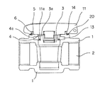
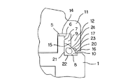
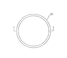
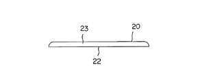
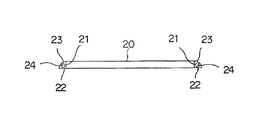
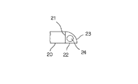
図1は本発明を実施したガス栓の断面図、図2は要部の断面図、図3は防水パッキンの平面図、図4は側面図、図5はA−A線断面図、図6は防水パッキンの一部拡大断面図である。
図1及び図2において、符号の1はガス栓本体であって、このガス栓本体1内には、水平方向にガス流路2が形成されていると共に、このガス流路2に直交するように閉子3が組み込まれている。4はガス栓本体1において、前記閉子3を組み込むためのハンドル取付口であって、このハンドル取付口4の上縁5の外周面6には、垂直壁7と水平壁8から成る断面L型の防水パッキン装着部9が形成されている。10はガス栓本体1において、前記防水パッキン装着部9の水平壁8の外側に形成された防水パッキン脱落防止用の段部である。
1 is a cross-sectional view of a gas stopper embodying the present invention, FIG. 2 is a cross-sectional view of a main part, FIG. 3 is a plan view of a waterproof packing, FIG. 4 is a side view, FIG. FIG. 4 is a partially enlarged sectional view of a waterproof packing.
In FIG. 1 and FIG. 2,
11はハンドル本体であって、このハンドル本体11の下部には、前記ガス栓本体1の外側に被る鍔部12が形成されていると共に、下面中央部分には、前記閉子3に形成した回転軸3aが係合する係合部11aが形成されている。更に、前記ハンドル取付口4の内周面に形成した円周回転溝4aと係合してハンドル本体11の回転を誘導する係合鍔13が形成されている。更に、ハンドル本体11の下面には、前記ハンドル取付口4の上縁5が収まる円周溝14が形成され、この円周溝14の外側の内周面15と下端面16とが交わる部分には、平面形状の防水パッキン圧接面17が形成されている。
20は防水パッキンであって、この防水パッキン20は、図3〜図6に示すように、内周に内周垂直密着面21を形成し、底部に底部水平密着面22を形成すると共に、この内周垂直密着面21と底部水平密着面22の外側に円弧状密着面23を形成し、更に内部に密閉された空洞24を形成した構成である。
上記構成の防水パッキン20は、図1及び図2に示すように、ガス栓本体1側に形成した防水パッキン装着部9の垂直壁7に内周垂直密着面21が密着し、水平壁8に底部水平密着面22が密着するようにして装着され、ハンドル本体11側の防水パッキン圧接面17は、防水パッキン20の円弧状密着面23に外側から圧接する。
この状態は、図2に良く示されていて、防水パッキン20の円弧状密着面23は、少しへこむように変形し、空洞24は楕円形に変形している。
なお、本実施例において、ハンドル本体11側の防水パッキン圧接面17は平面となっているが、凹曲面であっても良い。また、空洞24の断面形状は真円又は楕円形状が好ましいが、その他の形状であってもよい。
As shown in FIGS. 1 and 2, the
This state is well illustrated in FIG. 2, in which the arc-
In this embodiment, the waterproof packing
1 ガス栓本体
9 防水パッキン装着部
11 ハンドル本体
17 防水パッキン圧接面
20 防水パッキン
21 内周垂直密着面
22 底部水平密着面
23 円弧状密着面
24 空洞
DESCRIPTION OF
Claims (2)
The waterproof structure of the gas stopper according to claim 1, wherein the waterproof packing pressure contact surface is a flat surface or a concave curved surface.
Priority Applications (1)
| Application Number | Priority Date | Filing Date | Title |
|---|---|---|---|
| JP2004104620A JP2005291286A (en) | 2004-03-31 | 2004-03-31 | Waterproofing structure in gas plug |
Applications Claiming Priority (1)
| Application Number | Priority Date | Filing Date | Title |
|---|---|---|---|
| JP2004104620A JP2005291286A (en) | 2004-03-31 | 2004-03-31 | Waterproofing structure in gas plug |
Publications (1)
| Publication Number | Publication Date |
|---|---|
| JP2005291286A true JP2005291286A (en) | 2005-10-20 |
Family
ID=35324457
Family Applications (1)
| Application Number | Title | Priority Date | Filing Date |
|---|---|---|---|
| JP2004104620A Pending JP2005291286A (en) | 2004-03-31 | 2004-03-31 | Waterproofing structure in gas plug |
Country Status (1)
| Country | Link |
|---|---|
| JP (1) | JP2005291286A (en) |
-
2004
- 2004-03-31 JP JP2004104620A patent/JP2005291286A/en active Pending
Similar Documents
| Publication | Publication Date | Title |
|---|---|---|
| JP4978320B2 (en) | Valve and valve structure | |
| JP4017509B2 (en) | Sewing gasket and sewing machine using the same | |
| MX2007012934A (en) | Valve with bi-loading seal. | |
| JP2024001893A5 (en) | ||
| JP2005291286A (en) | Waterproofing structure in gas plug | |
| JP4545473B2 (en) | Waterproof structure in gas stopper | |
| US6533241B1 (en) | Retaining piece of a ball valve | |
| JP5156675B2 (en) | Gas stove | |
| CN206124727U (en) | Engine hydraulic suspension | |
| JP5612910B2 (en) | Pulsation damper of clutch operating device | |
| CN203686129U (en) | Steel wire ring structure metal air cylinder pad for engine | |
| JP6877240B2 (en) | Check valve | |
| JP2565484B2 (en) | Valve handle cap | |
| JP4677283B2 (en) | Head cover gasket positioning structure | |
| JP3001337U (en) | Gasket for portable gas appliances | |
| JP7220830B1 (en) | diaphragm valve | |
| JP4746528B2 (en) | gasket | |
| JP4778741B2 (en) | Butterfly valve | |
| CN215410352U (en) | Three-way ball valve structure | |
| US5454546A (en) | Water faucet mechanism | |
| JP2006057736A (en) | Oil seal | |
| JPH0449422Y2 (en) | ||
| KR100294111B1 (en) | Plug valve | |
| JP3126478U (en) | gasket | |
| JP2002349343A (en) | Head gasket |
Legal Events
| Date | Code | Title | Description |
|---|---|---|---|
| A711 | Notification of change in applicant |
Free format text: JAPANESE INTERMEDIATE CODE: A711 Effective date: 20050831 |