JP2005291285A - Suspension support - Google Patents
Suspension support Download PDFInfo
- Publication number
- JP2005291285A JP2005291285A JP2004104553A JP2004104553A JP2005291285A JP 2005291285 A JP2005291285 A JP 2005291285A JP 2004104553 A JP2004104553 A JP 2004104553A JP 2004104553 A JP2004104553 A JP 2004104553A JP 2005291285 A JP2005291285 A JP 2005291285A
- Authority
- JP
- Japan
- Prior art keywords
- metal fitting
- rubber
- elastic body
- outer cylinder
- suspension support
- Prior art date
- Legal status (The legal status is an assumption and is not a legal conclusion. Google has not performed a legal analysis and makes no representation as to the accuracy of the status listed.)
- Withdrawn
Links
- 239000000725 suspension Substances 0.000 title claims abstract description 38
- 239000002184 metal Substances 0.000 claims abstract description 61
- 238000003780 insertion Methods 0.000 claims description 11
- 230000037431 insertion Effects 0.000 claims description 11
- 239000006096 absorbing agent Substances 0.000 claims description 4
- 230000035939 shock Effects 0.000 claims description 4
- 238000006073 displacement reaction Methods 0.000 description 4
- 238000000465 moulding Methods 0.000 description 3
- 238000004073 vulcanization Methods 0.000 description 3
- 230000006835 compression Effects 0.000 description 2
- 238000007906 compression Methods 0.000 description 2
- 239000000463 material Substances 0.000 description 2
- 230000002093 peripheral effect Effects 0.000 description 2
- 238000004080 punching Methods 0.000 description 2
- 230000003247 decreasing effect Effects 0.000 description 1
- 238000000605 extraction Methods 0.000 description 1
- 230000002452 interceptive effect Effects 0.000 description 1
- 238000000034 method Methods 0.000 description 1
Images
Landscapes
- Fluid-Damping Devices (AREA)
Abstract
【課題】打音が生じにい構造でありながら、ばね定数をより小さくすることができ、コイルスプリングの上端の位置を変更しなくても済むサスペンションサポートを提供する。
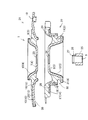
【解決手段】アッパー金具4に上広がりのテーパ筒部10を、ロアー金具5に下広がりのテーパ筒部12を設け、第1外筒部材13とアッパー金具4とゴム状弾性体3の上半部9とから成る上側サスペンションサポート部21と、第2外筒部材14とロアー金具5とゴム状弾性体3の下半部11とから成る下側サスペンションサポート部22とを互いに別体に成形するとともに、アッパー金具4の底壁7とロアー金具5の底壁8とを固着することで上側サスペンションサポート部21と下側サスペンションサポート部22とを一体に連結し、ゴム状弾性体3の上半部9と下半部11の間に空間Sを形成してある。
【選択図】 図2
Disclosed is a suspension support in which a spring constant can be further reduced and a position of an upper end of a coil spring does not need to be changed while having a structure that is difficult to generate a hitting sound.
An upper metal fitting is provided with a taper tube portion that extends upward, and a lower metal tube is provided with a taper tube portion that extends downward, and a first outer cylinder member, an upper metal fitting, and an upper half of a rubber-like elastic body. The upper suspension support portion 21 composed of the portion 9, the lower suspension support portion 22 composed of the second outer cylinder member 14, the lower metal fitting 5, and the lower half portion 11 of the rubber-like elastic body 3 are molded separately from each other. In addition, the upper suspension support portion 21 and the lower suspension support portion 22 are integrally connected by fixing the bottom wall 7 of the upper metal fitting 4 and the bottom wall 8 of the lower metal fitting 5, and the upper half of the rubber-like elastic body 3. A space S is formed between the part 9 and the lower half part 11.
[Selection] Figure 2
Description
本発明は、ショックアブソーバのピストンロッドを挿通させて連結する内筒と、車体側に取付けられる外筒とを、これらの間に介在させたゴム状弾性体で連結し、前記内筒を、ピストンロッド挿通孔を備えた上側開放カップ状のアッパー金具の底壁と、ピストンロッド挿通孔を備えた下側開放カップ状のロアー金具の底壁とを固着して形成し、前記アッパー金具に、前記外筒との間に前記ゴム状弾性体の上半部が加硫成形される上広がりのテーパ筒部を設けるとともに、前記ロアー金具に、前記外筒との間に前記ゴム状弾性体の下半部が加硫成形される下広がりのテーパ筒部を設けてあるサスペンションサポートに関する。 According to the present invention, an inner cylinder that is connected by inserting a piston rod of a shock absorber and an outer cylinder that is attached to the vehicle body are connected by a rubber-like elastic body interposed therebetween, and the inner cylinder is connected to a piston. The bottom wall of the upper open cup-shaped upper metal fitting provided with the rod insertion hole and the bottom wall of the lower open cup-shaped lower metal fitting provided with the piston rod insertion hole are fixedly formed. The upper half of the rubber-like elastic body is vulcanized and formed between the outer cylinder and an upwardly expanding tapered cylinder, and the lower metal fitting is placed under the rubber-like elastic body between the outer cylinder and the outer cylinder. The present invention relates to a suspension support provided with a downwardly expanding taper cylinder part in which a half part is vulcanized.
上記のサスペンションサポートは、ゴム状弾性体に生じる圧縮力で外筒と内筒の相対変位量を所定の範囲内に抑えることができ、例えば特許文献1の技術のように、上下方向で対向させたアッパー金具側の部分と外筒側の部分、及び、ロアー金具側の部分と外筒側の部分とを衝突させて前記相対変位量を抑さえる構造に比べると、打音が生じにくくなるという利点がある。
The suspension support described above can suppress the relative displacement between the outer cylinder and the inner cylinder within a predetermined range by a compressive force generated in the rubber-like elastic body. For example, as in the technique of
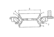
従来、この種のサスペンションサポートでは、図3に示すように、外筒2を単一部材で構成してあった。そして、ゴム状弾性体3をアッパー金具4やロアー金具5の最大径Dとほぼ同一径になるように加硫成形し、前記最大径Dよりも径方向の内方側で、かつ、アッパー金具4やロアー金具5の外周面よりも外方側を全てゴム状弾性体3で埋めてあった。
上記従来の構成によれば、アッパー金具やロアー金具の最大径よりも径方向の内方側で、かつ、アッパー金具やロアー金具の外周面よりも外方側が全てゴム状弾性体で埋まっていたために、ゴム状弾性体の量が多くなってばね定数を小さくすることができなかった。 According to the above-mentioned conventional configuration, the inner side in the radial direction is larger than the maximum diameter of the upper metal fitting and the lower metal fitting, and the outer side of the outer peripheral surface of the upper metal fitting and the lower metal fitting is all buried with the rubber elastic body. In addition, the amount of the rubber-like elastic body is increased and the spring constant cannot be reduced.
ばね定数を小さくする手段として、ゴム状弾性体にえぐり部が形成されるように加硫成形する手段があるが、アッパー金具の上広がりのテーパー筒部と、外筒の上広がりのテーパー筒部との間のゴム状弾性体が斜め下方にえぐれたり、ロアー金具の下広がりのテーパー筒部と、外筒の下広がりのテーパー筒部との間のゴム状弾性体が斜め上方にえぐれたりするように加硫成形することは、型抜きの際にえぐりに対応する型部分がテーパー筒部の最大径部分等と干渉して型抜きできなくなることから不可能であった。 As a means for reducing the spring constant, there is a means for vulcanization molding so that a hollow portion is formed in the rubber-like elastic body. However, the upper cylindrical portion of the upper bracket and the tapered cylindrical portion of the outer cylinder are expanded. The rubber-like elastic body between the upper part and the lower part of the lower bracket, and the rubber part between the tapered part and the lower part of the outer cylinder, go away diagonally upward. Such vulcanization molding is impossible because the mold part corresponding to the punching at the time of punching interferes with the maximum diameter part of the tapered tube part and the like and cannot be punched.
外筒にはシートスプリングラバー等を介してコイルスプリングを受けるフランジが形成されており、このフランジにゴム材を加硫成形してあることから、ばね定数を小さくする別の手段として、前記ゴム材の厚さを薄くすることも考えられるが、これではコイルスプリングの上端の位置が変更されてしまうという問題がある。 A flange that receives a coil spring via a seat spring rubber or the like is formed on the outer cylinder, and since the rubber material is vulcanized and formed on the flange, the rubber material is used as another means for reducing the spring constant. Although it is conceivable to reduce the thickness of the coil spring, there is a problem that the position of the upper end of the coil spring is changed.
本発明は上記実状に鑑みて成されたもので、その目的は、打音が生じにい構造でありながら、ばね定数をより小さくすることができ、しかも、コイルスプリングの上端の位置を変更しなくても済むサスペンションサポートを提供する点にある。 The present invention has been made in view of the above circumstances, and the object thereof is to reduce the spring constant while changing the position of the upper end of the coil spring while having a structure that is difficult to generate a hitting sound. It is to provide a suspension support that can be dispensed with.
本発明の特徴構成は、冒頭に記載したサスペンションサポートにおいて、前記外筒を、前記車体に対する第1取付けフランジを備えた第1外筒部材と、コイルスプリングの上端部を受止める第2取付けフランジを備えた第2外筒部材とから構成し、前記第1外筒部材とアッパー金具と前記ゴム状弾性体の上半部とから成る上側サスペンションサポート部と、前記第2外筒部材とロアー金具と前記ゴム状弾性体の下半部とから成る下側サスペンションサポート部とを互いに別体に成形するとともに、前記アッパー金具の底壁とロアー金具の底壁とを固着することで前記上側サスペンションサポート部と下側サスペンションサポート部とを一体に連結し、前記ゴム状弾性体の上半部と下半部の間に空間を形成し、車体に対する組付け状態で、前記第2取付けフランジの上面側又は前記第1取付けフランジの下面側に加硫成形したフランジ側ゴム状弾性体が、前記第1取付けフランジの下面又は前記第2取付けフランジの上面に圧接するよう構成してある点にある。 According to the characteristic configuration of the present invention, in the suspension support described at the beginning, the outer cylinder includes a first outer cylinder member having a first mounting flange with respect to the vehicle body, and a second mounting flange that receives an upper end portion of a coil spring. An upper suspension support portion comprising the first outer cylinder member, an upper metal fitting, and an upper half of the rubber-like elastic body, and the second outer cylinder member and a lower metal fitting. The upper suspension support portion is formed by forming the lower suspension support portion formed of the lower half portion of the rubber-like elastic body separately from each other and fixing the bottom wall of the upper metal fitting and the bottom wall of the lower metal fitting. And the lower suspension support part are integrally connected, and a space is formed between the upper half part and the lower half part of the rubber-like elastic body. (2) A flange-side rubber-like elastic body vulcanized and formed on the upper surface side of the mounting flange or the lower surface side of the first mounting flange is configured to be pressed against the lower surface of the first mounting flange or the upper surface of the second mounting flange. There is a point.
この構成によれば、第1外筒部材と前記上広がりのテーパ筒部との間にゴム状弾性体の上半部を加硫成形するとともに、第2外筒部材と前記下広がりのテーパ筒部との間にゴム状弾性体の下半部を加硫成形してあるから、振動の入力に伴ってゴム状弾性体に圧縮力とせん断力が作用するようになり、圧縮力だけが作用する構造よりもばね定数を小さくすることができる。そして、ゴム状弾性体に生じる圧縮力で外筒と内筒の相対変位量を所定の範囲内に抑えることができ、例えば、アッパー金具側の部分と外筒側の部分、及び、ロアー金具側の部分と外筒側の部分との衝突で前記相対変位量を抑える手段に比べると打音が生じにくくなる。 According to this configuration, the upper half portion of the rubber-like elastic body is vulcanized and formed between the first outer cylinder member and the upwardly expanding tapered cylinder part, and the second outer cylinder member and the downwardly expanding tapered cylinder are formed. Since the lower half of the rubber-like elastic body is vulcanized between the two parts, compression force and shear force act on the rubber-like elastic body as vibration is input, and only the compression force acts. The spring constant can be made smaller than that of the structure. And the relative displacement amount of the outer cylinder and the inner cylinder can be suppressed within a predetermined range by the compressive force generated in the rubber-like elastic body, for example, the upper metal part side, the outer cylinder side part, and the lower metal part side Compared with the means for suppressing the relative displacement due to the collision between the portion and the outer cylinder side portion, the hitting sound is less likely to occur.
また、上広がりのテーパ筒部と第1外筒部材に対するゴム状弾性体の上半部の加硫成形と、下広がりのテーパ筒部と第2外筒部材に対するゴム状弾性体の下半部の加硫成形とを別々に行うことができて、上側サスペンションサポート部と下側サスペンションサポート部とを一体に連結したときに、前記上半部と下半部との間に上記のように空間を形成することができる。この空間に対応する型部分を型抜きする場合は、上広がりのテーパー筒部の小径の端部側や、下広がりのテーパー筒部の小径の端部側に型抜きすることができるので、型抜きの際に型部分がアッパー金具やロアー金具の最大径部分等に干渉することがなく、前記空間の大きさを自由に設定することができる。そして、ゴム状弾性体の量を少なくすることができて、ばね定数を小さくすることができる。 Also, vulcanization molding of the upper half of the rubber-like elastic body with respect to the upwardly extending tapered cylindrical portion and the first outer cylinder member, and the lower half of the rubber-like elastic body with respect to the downwardly extending tapered cylindrical portion and the second outer cylindrical member When the upper suspension support portion and the lower suspension support portion are integrally connected, the space between the upper half portion and the lower half portion is as described above. Can be formed. When die-cutting the mold part corresponding to this space, the die can be die-cut to the small-diameter end side of the upwardly expanding tapered cylinder part or the small-diameter end part side of the downwardly-expanding tapered cylinder part. The size of the space can be freely set without the mold portion interfering with the maximum diameter portion of the upper metal fitting or the lower metal fitting during the extraction. And the quantity of a rubber-like elastic body can be decreased and a spring constant can be made small.
車体に対する組付け状態では、第2外筒部材の第2取付けフランジがコイルスプリングの上端部によって上方に押圧され、第2取付けフランジの上面側又は第1取付けフランジの下面側に加硫成形したフランジ側ゴム状弾性体が、第1取付けフランジの下面又は第2取付けフランジの上面に圧接するから、上側サスペンションサポート部と下側サスペンションサポート部とを確実に一体化することができる。 In the assembled state with respect to the vehicle body, the second mounting flange of the second outer cylinder member is pressed upward by the upper end portion of the coil spring, and is vulcanized and formed on the upper surface side of the second mounting flange or the lower surface side of the first mounting flange. Since the side rubber-like elastic body is pressed against the lower surface of the first mounting flange or the upper surface of the second mounting flange, the upper suspension support portion and the lower suspension support portion can be reliably integrated.
本発明において、前記アッパー金具の底壁に形成した第1貫通孔と、前記ロアー金具の底壁に形成した第2貫通孔とに、前記ピストンロッド挿通孔を備えたリング部材の縮径部を前記ロアー金具側から挿入し、前記リング部材の縮径部の先端部をかしめ固定して前記両底壁同士を固着してあると、両底壁同士を強固に固定することができる。 In the present invention, the reduced diameter portion of the ring member having the piston rod insertion hole is formed in the first through hole formed in the bottom wall of the upper metal fitting and the second through hole formed in the bottom wall of the lower metal fitting. If both the bottom walls are fixed by caulking and fixing the tip of the reduced diameter portion of the ring member by inserting from the lower metal fitting side, the two bottom walls can be firmly fixed.
本発明によれば、打音が生じにい構造でありながら、ばね定数をより小さくすることができ、しかも、コイルスプリングの上端の位置を変更しなくても済むサスペンションサポートを提供することができた。 According to the present invention, it is possible to provide a suspension support in which the spring constant can be further reduced and the position of the upper end of the coil spring does not need to be changed while having a structure that is difficult to generate a hitting sound. It was.
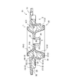
以下、本発明を実施するための最良の形態を図面に基づいて説明する。図1,図2に示すように、自動車のショックアブソーバのピストンロッドを挿通させて連結する内筒1と、車体側に取付けられる外筒2とを、これらの間に介在させたゴム状弾性体3で連結し、内筒1を、ピストンロッド挿通孔6を備えた上側開放カップ状のアッパー金具4の底壁7と、ピストンロッド挿通孔6を備えた下側開放カップ状のロアー金具5の底壁8とを固着してサスペンションサポートを構成してある。
Hereinafter, the best mode for carrying out the present invention will be described with reference to the drawings. As shown in FIGS. 1 and 2, a rubber-like elastic body in which an
内筒1のアッパー金具4は、前記底壁7に、外筒2との間にゴム状弾性体3の上半部9が加硫成形される上広がりのテーパ筒部10を連設して構成され、ロアー金具5は、前記底壁8に、外筒2との間にゴム状弾性体3の下半部11が加硫成形される下広がりのテーパ筒部12を連設して構成されている。この下広がりのテーパ筒部12の下端部にフランジ31を連設してある。
The
外筒2は第1外筒部材13と第2外筒部材14との二つの金属製の部材から成る。第1外筒部材13は、車体に対する第1取付けフランジ15と緩やかに下方に窄む筒部16とを備え、第2外筒部材14は、ショックアブソーバが挿通するコイルスプリングの上端部を受止める第2取付けフランジ17と下広がりの筒部18とを備えている。図示はしてないが、第1取付けフランジ15は平面視で丸みを帯びた三角形状に形成され、その頂部付近にそれぞれボルト挿通孔19が貫通形成されている。また第1取付けフランジ15の上面に、ゴム状弾性体3の上半部9に連なるゴム状弾性体20を加硫成形してある。第2外筒部材14の下広がりの筒部18の下端部と、ロアー金具5の下端側のフランジ31との間のゴム状弾性体3の下半部11にすぐり穴32を形成してある。このすぐり穴32はロアー金具5の径方向内方側に向かってえぐられている。
The
そして、図2に示すように、第1外筒部材13とアッパー金具4とゴム状弾性体3の上半部9とから成る上側サスペンションサポート部21と、第2外筒部材14とロアー金具5とゴム状弾性体3の下半部11とから成る下側サスペンションサポート部22とを互いに別体に成形しておき、アッパー金具4の底壁7とロアー金具5の底壁8とを固着することで上側サスペンションサポート部21と下側サスペンションサポート部22とを一体に連結してある。
Then, as shown in FIG. 2, the upper
つまり、アッパー金具4の底壁7に形成した第1貫通孔23と、ロアー金具5の底壁8に形成した第2貫通孔24とに、前記ピストンロッド挿通孔6を備えたリング部材25の縮径部26をロアー金具5側から挿入(詳しくは圧入)し、リング部材25の縮径部26の先端部27をかしめ固定して両底壁7,8同士を固着してある。この連結状態で、ゴム状弾性体3の上半部9と下半部11の間に、アッパー金具4の底部とロアー金具5の底部を囲む環状の空間Sを形成し、車体に対する組付け状態で、第2取付けフランジ17の上面28側に加硫成形したフランジ側ゴム状弾性体29が、第1取付けフランジ15の下面30に圧接するよう構成してある。
That is, the
[別実施形態]
車体に対する組付け状態で、第1取付けフランジ17の下面30側に加硫成形したフランジ側ゴム状弾性体が、第2取付けフランジ17の上面28に圧接するよう構成してあってもよい。車体に対する組付け状態で、第1取付けフランジ17の下面30側に加硫成形したフランジ側ゴム状弾性体と、第2取付けフランジ17の上面28側に加硫成形したフランジ側ゴム状弾性体とが互いに圧接するよう構成してあってもよい。
[Another embodiment]
The flange-side rubber-like elastic body vulcanized and formed on the
1 内筒
2 外筒
3 ゴム状弾性体
4 アッパー金具
5 ロアー金具
6 ピストンロッド挿通孔
7 アッパー金具の底壁
8 ロアー金具の底壁
9 ゴム状弾性体の上半部
10 上広がりのテーパ筒部
11 ゴム状弾性体の下半部
12 下広がりのテーパ筒部
13 第1外筒部材
14 第2外筒部材
15 第1取付けフランジ
17 第2取付けフランジ
21 上側サスペンションサポート部
22 下側サスペンションサポート部
23 第1貫通孔
24 第2貫通孔
25 リング部材
26 縮径部
27 先端部
28 第2取付けフランジの上面
29 フランジ側ゴム状弾性体
30 第1取付けフランジの下面
S 空間
DESCRIPTION OF
Claims (2)
前記外筒を、前記車体に対する第1取付けフランジを備えた第1外筒部材と、コイルスプリングの上端部を受止める第2取付けフランジを備えた第2外筒部材とから構成し、前記第1外筒部材とアッパー金具と前記ゴム状弾性体の上半部とから成る上側サスペンションサポート部と、前記第2外筒部材とロアー金具と前記ゴム状弾性体の下半部とから成る下側サスペンションサポート部とを互いに別体に成形するとともに、前記アッパー金具の底壁とロアー金具の底壁とを固着することで前記上側サスペンションサポート部と下側サスペンションサポート部とを一体に連結し、前記ゴム状弾性体の上半部と下半部の間に空間を形成し、車体に対する組付け状態で、前記第2取付けフランジの上面側又は前記第1取付けフランジの下面側に加硫成形したフランジ側ゴム状弾性体が、前記第1取付けフランジの下面又は前記第2取付けフランジの上面に圧接するよう構成してあるサスペンションサポート。 An inner cylinder that is connected by inserting the piston rod of the shock absorber and an outer cylinder that is attached to the vehicle body side are connected by a rubber-like elastic body interposed therebetween, and the inner cylinder is connected to the piston rod insertion hole. The bottom wall of the upper open cup-shaped upper metal fitting provided and the bottom wall of the lower open cup-shaped lower metal fitting provided with the piston rod insertion hole are fixed, and the upper metal fitting is connected to the outer cylinder. The upper half of the rubber-like elastic body is vulcanized and formed with an upwardly expanding tapered cylinder, and the lower half of the rubber-like elastic body is added to the lower fitting between the outer cylinder. Suspension support provided with a downwardly expanding taper cylindrical portion to be molded,
The outer cylinder includes a first outer cylinder member having a first mounting flange with respect to the vehicle body, and a second outer cylinder member having a second mounting flange for receiving an upper end portion of a coil spring. An upper suspension support portion comprising an outer cylinder member, an upper metal fitting, and an upper half portion of the rubber-like elastic body, and a lower suspension comprising the second outer cylinder member, a lower metal fitting and a lower half portion of the rubber-like elastic body. The support portion is formed separately from each other, and the upper suspension support portion and the lower suspension support portion are integrally connected by fixing the bottom wall of the upper metal fitting and the bottom wall of the lower metal fitting, and the rubber A space is formed between the upper half portion and the lower half portion of the elastic body, and vulcanized on the upper surface side of the second mounting flange or the lower surface side of the first mounting flange in an assembled state with respect to the vehicle body. Suspension support form flanges side rubber-like elastic body, are configured to press the lower surface or upper surface of the second mounting flange of the first mounting flange.
Priority Applications (1)
| Application Number | Priority Date | Filing Date | Title |
|---|---|---|---|
| JP2004104553A JP2005291285A (en) | 2004-03-31 | 2004-03-31 | Suspension support |
Applications Claiming Priority (1)
| Application Number | Priority Date | Filing Date | Title |
|---|---|---|---|
| JP2004104553A JP2005291285A (en) | 2004-03-31 | 2004-03-31 | Suspension support |
Publications (1)
| Publication Number | Publication Date |
|---|---|
| JP2005291285A true JP2005291285A (en) | 2005-10-20 |
Family
ID=35324456
Family Applications (1)
| Application Number | Title | Priority Date | Filing Date |
|---|---|---|---|
| JP2004104553A Withdrawn JP2005291285A (en) | 2004-03-31 | 2004-03-31 | Suspension support |
Country Status (1)
| Country | Link |
|---|---|
| JP (1) | JP2005291285A (en) |
-
2004
- 2004-03-31 JP JP2004104553A patent/JP2005291285A/en not_active Withdrawn
Similar Documents
| Publication | Publication Date | Title |
|---|---|---|
| US7389977B1 (en) | Body mount assembly with combined shear and compression style components | |
| US8191692B2 (en) | Cylinder apparatus | |
| CN110035945B (en) | Vehicle frame support device | |
| JP2009243483A (en) | Resin torque rod | |
| US10661648B2 (en) | Rubber stopper | |
| JP2004505843A (en) | Fluid damping bearing | |
| US10300953B2 (en) | Hydraulic body mount | |
| JP2009222164A (en) | Bound stopper | |
| JP2005291285A (en) | Suspension support | |
| JP2004232824A (en) | Strut mount | |
| EP3227132B1 (en) | Piston design with increased lateral strength | |
| JP2009180330A (en) | Automobile cylindrical vibration absorbing device manufacturing method | |
| JP2003090375A (en) | Cylindrical vibration isolator | |
| JP2005054872A (en) | Suspension support | |
| JP2000006630A (en) | Coil spring vibration control supporting device | |
| CN116928284A (en) | Cylindrical support | |
| JP2001271864A (en) | Bound stopper | |
| KR20190010158A (en) | Mounting bush for vehicle and installation method thereof | |
| JP3987544B2 (en) | Strut mount | |
| JP2008002565A (en) | Vibration isolator | |
| JP2004353718A (en) | Suspension support | |
| JP4127407B2 (en) | Strut mount | |
| JP3775264B2 (en) | Stopper with dust cover | |
| JP2006002803A (en) | Suspension support | |
| JP2001311444A (en) | Hydraulic shock absorber |
Legal Events
| Date | Code | Title | Description |
|---|---|---|---|
| A621 | Written request for application examination |
Effective date: 20060126 Free format text: JAPANESE INTERMEDIATE CODE: A621 |
|
| A761 | Written withdrawal of application |
Free format text: JAPANESE INTERMEDIATE CODE: A761 Effective date: 20070612 |