JP2005291248A - Linear slider and manufacturing method thereof - Google Patents
Linear slider and manufacturing method thereof Download PDFInfo
- Publication number
- JP2005291248A JP2005291248A JP2004103644A JP2004103644A JP2005291248A JP 2005291248 A JP2005291248 A JP 2005291248A JP 2004103644 A JP2004103644 A JP 2004103644A JP 2004103644 A JP2004103644 A JP 2004103644A JP 2005291248 A JP2005291248 A JP 2005291248A
- Authority
- JP
- Japan
- Prior art keywords
- hole
- slider
- reflow
- linear
- slot
- Prior art date
- Legal status (The legal status is an assumption and is not a legal conclusion. Google has not performed a legal analysis and makes no representation as to the accuracy of the status listed.)
- Pending
Links
Images


Classifications
-
- F—MECHANICAL ENGINEERING; LIGHTING; HEATING; WEAPONS; BLASTING
- F16—ENGINEERING ELEMENTS AND UNITS; GENERAL MEASURES FOR PRODUCING AND MAINTAINING EFFECTIVE FUNCTIONING OF MACHINES OR INSTALLATIONS; THERMAL INSULATION IN GENERAL
- F16C—SHAFTS; FLEXIBLE SHAFTS; ELEMENTS OR CRANKSHAFT MECHANISMS; ROTARY BODIES OTHER THAN GEARING ELEMENTS; BEARINGS
- F16C29/00—Bearings for parts moving only linearly
- F16C29/04—Ball or roller bearings
- F16C29/06—Ball or roller bearings in which the rolling bodies circulate partly without carrying load
- F16C29/0602—Details of the bearing body or carriage or parts thereof, e.g. methods for manufacturing or assembly
- F16C29/0604—Details of the bearing body or carriage or parts thereof, e.g. methods for manufacturing or assembly of the load bearing section
-
- F—MECHANICAL ENGINEERING; LIGHTING; HEATING; WEAPONS; BLASTING
- F16—ENGINEERING ELEMENTS AND UNITS; GENERAL MEASURES FOR PRODUCING AND MAINTAINING EFFECTIVE FUNCTIONING OF MACHINES OR INSTALLATIONS; THERMAL INSULATION IN GENERAL
- F16C—SHAFTS; FLEXIBLE SHAFTS; ELEMENTS OR CRANKSHAFT MECHANISMS; ROTARY BODIES OTHER THAN GEARING ELEMENTS; BEARINGS
- F16C29/00—Bearings for parts moving only linearly
- F16C29/04—Ball or roller bearings
- F16C29/06—Ball or roller bearings in which the rolling bodies circulate partly without carrying load
- F16C29/0633—Ball or roller bearings in which the rolling bodies circulate partly without carrying load with a bearing body defining a U-shaped carriage, i.e. surrounding a guide rail or track on three sides
- F16C29/0635—Ball or roller bearings in which the rolling bodies circulate partly without carrying load with a bearing body defining a U-shaped carriage, i.e. surrounding a guide rail or track on three sides whereby the return paths are provided as bores in a main body of the U-shaped carriage, e.g. the main body of the U-shaped carriage is a single part with end caps provided at each end
Landscapes
- Engineering & Computer Science (AREA)
- General Engineering & Computer Science (AREA)
- Mechanical Engineering (AREA)
- Bearings For Parts Moving Linearly (AREA)
Abstract
Description
本発明は、装置等の運動機構移動方向を導引するリニアトラックのスライダー(リニアスライダーと称される)とその製造方法に関するものであって、特に、リニアスライダーのコストダウン製造方法に関するものである。 The present invention relates to a linear track slider (referred to as a linear slider) that guides the moving direction of a motion mechanism of an apparatus or the like and a method for manufacturing the same, and more particularly to a method for manufacturing a linear slider at a reduced cost. .
装置等の運動機構移動方向を導引するリニアトラックは、重要な機械素子で、現在、幅広く、精密機械、自動化産業、半導体産業、医療設備、航空宇宙工業等、主要な効用は、ボール(ball)、或いは、ローラー(roller)の回転により、機構移動時の摩擦抵抗を低下させ、機構移動時、更に、省力、且つ、エネルギー節約を可能にし、同時に、摩擦の減少、接触面の摩損と温度上昇の減少により、機構の精度向上及び寿命を延長させ、機構の移動速度が大幅に増加し、これにより、リニアトラックは、近年来の重要な機械伝動素子の一つである。
通常、リニアトラックは、二種に分けられ、ボールを使用したリニアボールトラックと、もう一つは、ローラーを使用したリニアローラートラックである。
これらリニアトラックは、ボールであっても、ローラーであっても、スライダー上にローラー素子(ボール、或いは、ローラー)搭載及び循環リフロー等の機能を有する必要があるので、構造が複雑で、加工の回数、コストも高くなる。
リニアボールスライダー(図10を参照)は、スライダー8上に、ローラー素子(ボール)搭載の機能を有するので、スライダー8上に、スロット81を設置する必要があり、スロット81はローラー素子が動くトラックで、機構の負荷を搭載するのに用いられる。よって、スロット81表面は、材料の耐摩耗性を達成する高い硬度(HRC58以上)が必要で、スロット81付近の材質も、材料の疲労破壊を回避する降伏強度(yielding strength)を有していなければならない。ローラー素子は反対方向の移動が出来、無限の循環回転させる目的を達成するため、スライダー8上に、リフロー孔82を設置している。
The linear track that guides the moving direction of the motion mechanism of the device is an important mechanical element. Currently, it is widely used in the precision machinery, automation industry, semiconductor industry, medical equipment, aerospace industry, etc. ) Or, by rotating the roller, the frictional resistance at the time of moving the mechanism is reduced, and at the time of moving the mechanism, further labor saving and energy saving are possible, and at the same time, friction is reduced, contact surface wear and temperature are reduced. The decrease in the lift increases the accuracy and life of the mechanism and greatly increases the speed of movement of the mechanism, which makes the linear track one of the most important mechanical transmission elements in recent years.
Usually, the linear track is divided into two types, a linear ball track using balls, and the other is a linear roller track using rollers.
These linear tracks, whether balls or rollers, need to have functions such as mounting a roller element (ball or roller) on the slider and circulating reflow, so the structure is complicated and The number of times and cost also increase.
Since the linear ball slider (see FIG. 10) has a function of mounting a roller element (ball) on the
リフロー孔82は通孔で、一般のリフロー孔82は、機械加工(ドリル)の方式により、円形断面の孔を形成し、スライダーの一端面からもう一つの端面に貫通し、ローラー素子が通過できるようになっており、よって、リフロー孔82の寸法は、ローラー素子より大きい。但し、小さすぎて、ローラー素子がリフロー孔82中で詰まって、動きが円滑でなくならないようにしなければならない。スライダー8の長さは、充分な搭載負荷を提供するのに充分に長くなければならず、故に、リフロー82の深さも深く、通常、孔の深さは孔径の10倍程度で、加工上、非常に困難である。また、リフロー孔82はドリルのドリル用ビットが鈍化すれば、ドリルの偏移を生じ、リフロー孔82は、スライダー8の両端面上で、出口位置が異なってしまう。近来、リテイナー(retainer)を装着したリニアボールトラックの設計(特許文献1:USP.6042269、或いは、特許文献2:USP.6085420)は、リフロー孔が、ローラー素子とリテイナーを同時に通過できるようにしなければならないので、リフロー孔は円形断面の両側に、別途に翼型スロット821を設置し、翼型スロット821はリテイナー(図示しない)を通過させるのに用いられる。翼型スロット821の加工は非常に困難である。
The
よって、公知の製造方法は、スライダー8上方に、まず、大通孔84を設置し、熱処理硬化後、研磨し、更に、精密射出成形の特許製造方法により、大通孔84中に、プラスチック材質のプラスチック充填ブロック85を形成しているが、製造方式は複雑で、難度が高い。また、スライダー8の限られた空間中、孔が大きければ、スライダーの構造が不安定になり、よって、スライダー8中にドリルされる大通孔84は、スライダー8の構造強度を低下させなければならない。この他、スライダー8の両端上も、ねじ孔83を加工し、ねじ孔83は、スライダー8の両端面上に設けられた端蓋(図示しない)を固定するのに用いられる。ねじ孔を加工するのは困難ではないが、ねじ孔83とリフロー孔82は、それぞれ、きっちりと相対関係をなさなければならないので、加工の困難度が高く、機器の精度、或いは、刀具の因素で、ミスアライメントを生じ、スライダーの品質が保証されない。
Therefore, in the known manufacturing method, a large through
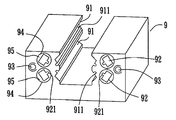
一方、図11で示されるリニアローラートラックは、スライダー9上に、ローラー素子(ローラー)搭載の機能を有するので、スライダー9上に、同様に、スロット91を設置する必要がある。スロット91は、ローラー素子のトラックで、機構の負荷を搭載するのに用いられる。よって、スロット91表面及び付近の材質は、材料の疲労破壊を回避できる高い硬度及び降伏強度を有していなければならない。
ローラー素子が反対方向に移動して、無限の循環回転させる目的を達成するため、スライダー9上に、リフロー孔92を設置する。リフロー孔92は通孔であるが、ローラーの側面プロフィルに合わせるため、リフロー孔92は、四角形断面の孔に設計され、円形の孔は加工が容易であるが、四角形の加工難度も、コストも高い。
現在使用されている方法は、まず、スライダー9に、円形の大通孔94をドリルし、更に、プラスチック充填ブロック95をその中に埋め(特許文献3:USP6109789)ために、リニアボールトラックと同様、構造強度が低下する状況を有する。
On the other hand, since the linear roller track shown in FIG. 11 has a function of mounting a roller element (roller) on the
A
In the method currently used, first, a circular large through
この他、リニアボールトラックがリテイナーを使用する時、リフロー孔は同時にローラー素子及びリテイナーとが通過できないといけないので、リフロー92が接近するスロット91の一側に、翼型スロット921を設置し、翼型スロット921は、リテイナーを通過させるのに用いられ、この他、スライダーのスロット91上にも、スロット91と平行な逃スロット911を対応して設置し、リテイナーが通過できるようにする。公知の製造方法も、まず、スロット9上に大通孔94をドリルし、更に、予め形成したプラスチック充填ブロック95をその中に充填し(特許文献4:USP6390678)ているが、製造工程が複雑なだけでなく、プラスチックの強度も鉄鋼材とは程遠く、故に、スライダーの構造強度も低下する。この他、スライダー9の両端面上にも、ねじ孔93を加工し、ねじ孔93も同様に、相対位置の問題があり、よって、加工の困難度が高い。
上述したように、従来公知のリニアスライダー及びその製造方法には種々の不都合があった。
本発明は、このような不都合に鑑みてなされたもので、加工が容易であって、機器の精度も高く維持でき、生産しやすいリニアスライダーとその製造方法を提供し、コストを減少させ、リフロー孔がドリル孔の不良により偏離する問題を回避することができるリニアスライダー及びその製造方法を提供するものである。
As described above, the conventional linear slider and its manufacturing method have various disadvantages.
The present invention has been made in view of such inconveniences, and provides a linear slider and a manufacturing method thereof that are easy to process, maintain high accuracy of equipment, and are easy to produce, reduce costs, and reflow. It is an object of the present invention to provide a linear slider and a method for manufacturing the same that can avoid the problem that the holes are deviated due to defective drill holes.
上記課題を解決するために、請求項1の発明は、リニアスライダーであって、ローラー素子に循環リフロー用のリフロー孔を設け、前記スライダーは、ロストワックス鋳造により製造され、前記リフロー孔は通孔で、且つ、孔の深さが孔径の5倍以上であることを特徴とするスライダーである。
請求項2の発明は、前記リフロー孔上に、平行な翼型スロットを有することを特徴とする請求項1に記載のスライダーである。
請求項3の発明は、前記リフロー孔はテーパ段を有することを特徴とする請求項1に記載のスライダーである。
請求項4の発明は、前記リフロー孔はステップを有することを特徴とする請求項1に記載のスライダーである。
請求項5の発明は、リニアスライダーの製造方法であって、ローラー素子に循環リフロー用のリフロー孔を設け、前記リフロー孔の中間部分の孔径は、両端出口の孔径より小さく、且つ、ロストワックス鋳造の方法で製造され、前記ロストワックスで使用されるロウ型は、右キャストと左キャストを備え、前記右キャストと左キャストの接合線は、前記リフロー孔の中間位置に設置されることを特徴とする方法である。
In order to solve the above problems, the invention of
According to a second aspect of the present invention, the slider according to the first aspect of the present invention has parallel airfoil slots on the reflow hole.
The invention according to claim 3 is the slider according to
According to a fourth aspect of the present invention, in the slider according to the first aspect, the reflow hole has a step.
The invention of claim 5 is a method of manufacturing a linear slider, wherein the roller element is provided with a reflow hole for circulation reflow, the hole diameter of the intermediate part of the reflow hole is smaller than the hole diameter of the outlets at both ends, and lost wax casting The wax type used in the lost wax and used in the lost wax is provided with a right cast and a left cast, and a joining line between the right cast and the left cast is installed at an intermediate position of the reflow hole. It is a method to do.
ところで、コストを減少させるため、鋳造、熱鍛、及び熱間押し出し等が考慮される方法であるが、公知の鋳造、熱鍛、及び熱間押し出しは、リフロー孔の成形が困難で、形成後の製品は、複数の加工を施さなければならないので、生産コストは減少しがたい。
ロストワックス鋳造は高精度の鋳造方法で、寸法精度が高いので、リニアスライダーの製造における問題を解決する方法であるが、孔の製造能力が好ましくなく、通孔(前後に貫通する孔)の孔深さ(通孔なので、孔深さは孔の全長である)と孔径比は、4倍以内にしかできないが、不幸にも、通常、リニアスライダーのリフロー孔の孔深さ孔径比は、10倍ほど、少なくても5倍を下らないので、ロストワックス鋳造は、リフロー孔を有するリニアスライダーの製造方法となることが出来ない。
By the way, in order to reduce costs, casting, thermal forging, hot extrusion, and the like are considered, but known casting, thermal forging, and hot extrusion are difficult to form reflow holes. This product has to be processed multiple times, so the production cost is difficult to reduce.
Lost wax casting is a high-precision casting method that has high dimensional accuracy, and is a method that solves problems in the production of linear sliders. The depth (the hole depth is the total length of the hole since it is a through hole) and the hole diameter ratio can only be within 4 times, but unfortunately the hole depth ratio of the reflow hole of the linear slider is usually 10 Since it does not drop at least 5 times as much as twice, lost wax casting cannot be a method for manufacturing a linear slider having reflow holes.
ロストワックス鋳造の通孔製造上の主な問題は、ロストワックスの過程で、ロウ型の型抜き工程において、ロウは柔らかい材料であるため、ロウ型型抜き時、ワックス表面を傷つけてしまうことである。ロストワックス鋳造法により、リニアスライダーを製造するため、本発明は、リフロー孔の中間部分の孔径を小さくし、即ち、リニアスライダーのローラー素子が通過すればよいことを知見したこと基礎とするもので、両端の出口の孔径は大きいので、ロウ型の型抜きが容易である。
本発明のリフロー孔の設計が、主に採用する手段は、リフロー孔中に、テーパ段、或いは、ステップを設置し、テーパ段を設置する時、リフロー孔のテーパ度は、ロウ型の型抜きを容易にする。ステップの設置は、リフロー孔を数段の異なる孔径に分け、一段のステップの長さは、孔径の4倍より小さい。よって、ロウ型の型抜きを容易にする。これにより、テーパ度を有するリフロー孔、或いは/及びステップ設計のリフロー孔は、ロストワックス鋳造法を使用し、リニアスライダーの製造を便利にし、製造コストを減少させるだけでなく、製品の寸法安定度も向上できる。
この他、本発明におけるリフロー孔の設計と合わせて、本発明は、ロウ型の型抜きの新設計を提供し、ロウ型の接合線は、リニアスライダーのリフロー孔の中段に設計され、型抜きが容易で、これにより、リニアスライダーのリフロー孔の深さは、リフロー孔最小孔径の5倍以上になる。
The main problem in lost-wax casting through-hole manufacturing is that in the process of lost wax, the wax is a soft material in the process of mold removal of the wax mold. is there. In order to manufacture a linear slider by the lost wax casting method, the present invention is based on the knowledge that the hole diameter of the intermediate portion of the reflow hole should be reduced, that is, the roller element of the linear slider should pass. Since the hole diameters at the outlets at both ends are large, it is easy to remove the wax mold.
The reflow hole design of the present invention mainly adopts a taper step or a step in the reflow hole, and when the taper step is installed, the taper degree of the reflow hole is determined by removing the die of the wax type. To make it easier. In the installation of the step, the reflow hole is divided into several different hole diameters, and the length of one step is smaller than four times the hole diameter. Therefore, it is easy to remove the wax mold. As a result, reflow holes with taper and / or reflow holes with step design use lost wax casting method, making the manufacture of linear slider convenient and reducing the manufacturing cost, as well as the dimensional stability of the product Can also be improved.
In addition to the design of the reflow hole in the present invention, the present invention provides a new design of the wax die cutting, and the solder joint line is designed in the middle stage of the reflow hole of the linear slider. Thus, the depth of the reflow hole of the linear slider becomes 5 times or more the minimum hole diameter of the reflow hole.
本発明によれば、リニアスライダーをロストワックス鋳造により製造することにより、ローラー素子に循環リフロー用のリフロー孔の加工が容易とない、尚かつ、従来のようにリフロー孔がドリル孔の不良により偏離する問題もなく、機器の精度も高く維持でき、生産しやすくなりコストを減少させることができるという効果が得られる。 According to the present invention, by manufacturing the linear slider by lost wax casting, it is not easy to process the reflow hole for circulating reflow on the roller element, and the reflow hole is not separated due to a defective drill hole as in the conventional case. There is no problem, and the accuracy of the equipment can be maintained high, and it is easy to produce and the cost can be reduced.
本発明の好適な実施例を図面を参照して説明する。
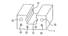
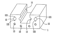
図1は、本発明の実施例のリニアボールスライダーの立体図である。図中のスライダー1上に二本のスロット11を設け、スロット11はローラー素子(ボール)のトラックで、機構の負荷を搭載するのに用いられる。よって、スロット11表面は、高い硬度を有し、材料の耐磨耗性を得ると同時に、スロット11付近の材質も、材料の疲労破壊を回避する降伏強度を有していなければならない。
ローラー素子が反対方向に移動して、無限の循環回転させる目的を達成するため、スライダー1上に、各スロット11に合わせて、リフロー孔12を設置し、リフロー孔12は通孔で、スライダー1の端面からもう一つの端面に貫通し、その尺寸は、ローラーより若干大きく、ローラー素子が通過でき、且つ、孔内で満杯になって、動きが円滑でなくならないようになっている。スライダー1の両端面上の端蓋(図示しない)を固定するため、スライダー1の両端面上に、それぞれ、ねじ孔13が設置されて、端蓋を固定している。リニアボールスライダー1の製造を便利にするため、本発明のリニアボールスライダー1は、ロストワックス鋳造法を使用しているが、ロストワックス鋳造法を製造方法に使用するために、本発明は、リフロー孔の中間部分の孔径を小さく設計し、つまり、リニアスライダーのローラー素子が通過できればよい。両端の出口の孔径は大きく、ロウ型の型抜きに便利である。
Preferred embodiments of the present invention will be described with reference to the drawings.
FIG. 1 is a three-dimensional view of a linear ball slider according to an embodiment of the present invention. Two
In order to achieve the purpose of infinite circulation and rotation by moving the roller element in the opposite direction, a
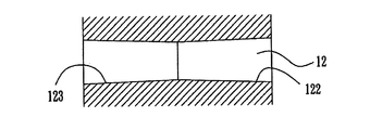
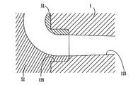
図2は、本発明のリニアボールスライダーのリフロー孔の第一実施例の断面図である。 リフロー孔12中、テーパ段122及びもう一つのテーパ段123を備え、テーパ段122及び123はテーパ状になっているので、ロストワックス鋳造工程中、ロウ型の型抜きが容易である。
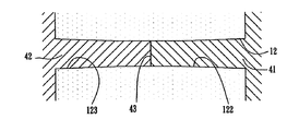
図3は、本発明のリニアボールスライダーのリフロー孔の第二実施例の断面図である。リフロー孔12は、テーパ段122、123、及び、直孔段124が組み合わされてなり、テーパ段122及び123はテーパ状になっているので、ロストワックス鋳造工程中、ロウ型の型抜きが容易である。直孔段124はリフロー孔12の総長さ(孔の深さ)を増加するのに用いられる。
図4は、図3の実施例のロストワックス工程を示す図である。ロストワックスが使用するロウ型は、右キャスト41及び左キャスト42を組み合わせてなり、右キャスト41と左キャスト42間の接合線43は、リフロー孔12の中間位置に設置され、テーパ段122及び123はテーパ状になっており、それが、ちょうど、金型の型抜きの角になっているので、右キャスト41及び左キャスト42の型抜きが容易である。型抜きを容易にするため、テーパ段のテーパ度は1度以上、好ましくは2度に設計してある。ある設計において、深いリフロー孔を必要とする時、ロストワックス鋳造法により、テーパ段122及び123を備えるリニアボールスラーダーを鋳造した後、ドリル開け加工方式により、直孔段124を加工する。直孔段124の効用は、ローラー素子の通過を可能にするだけなので、精度及び定位の問題が生じない故、リフロー孔でテーパ段を有する状況下で、直孔段124の加工は容易である。
FIG. 2 is a cross-sectional view of the first embodiment of the reflow hole of the linear ball slider of the present invention. In the
FIG. 3 is a cross-sectional view of a second embodiment of the reflow hole of the linear ball slider of the present invention. The
FIG. 4 is a diagram showing a lost wax process of the embodiment of FIG. The wax type used by the lost wax is a combination of the right cast 41 and the left cast 42, and the
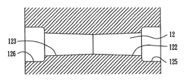
図5は、本発明のリニアボールスライダーのリフロー孔の第三実施例の断面図である。図中のリフロー孔12は、テーパ段122及び123を備える以外に、二つのステップ125及び126を備える。テーパ段122及び123はテーパ状になっているので、ロストワックス鋳造工程中、ロウ型の型抜きが容易で、ステップ125及び126は、孔径が大きくなるため、ワックスの強度が増加し、故に、型抜き工程において、不良事態が生じにくく、ステップ125及び126の設置も、リフロー孔12の総長さ(孔深)も増加させることができる。
図6は、本発明のリニアボールスライダーのリフロー孔の第四実施例の断面図である。 図中の直孔段124の設置は、リフロー孔12の総長さ(孔深)を増加させる。
FIG. 5 is a sectional view of a third embodiment of the reflow hole of the linear ball slider of the present invention. The
FIG. 6 is a sectional view of a fourth embodiment of the reflow hole of the linear ball slider of the present invention. Installation of the
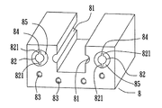
図7は、図5の実施例中のステップ付近の組み合わせ図である。図中のステップ126中、ローラー素子を転向素子51及び52に挿設し、転向素子51及び52は、ローラー素子に、その運動方向を変更させるのに用いられ、本発明の実施例でのステップ126と転向素子51及び52の設計は、公知技術中の大通孔84とは異なる。公知技術中の大通孔84は、一つの貫通孔で、構造強度減少に対する影響が非常に大きく、ステップ126はリフロー孔12両端の小さい部分に設置され、構造強度の減少に対する影響がそれほど大きくない。
FIG. 7 is a combination diagram in the vicinity of the steps in the embodiment of FIG. During
図8は本発明のリニアローラースライダーの実施例の立体図である。上述したリニアボールスラーダーと同様、図中で増設された翼型スロット121に関し、本発明の実施例は、ロストワックス鋳造方式により、スライダー1を製作するので、翼型スロット121を増設するのは、製作困難度を増加させない。
FIG. 8 is a three-dimensional view of an embodiment of the linear roller slider of the present invention. As with the linear ball slurder described above, with respect to the
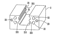
図9は、本発明のリニアローラースライダーの別の実施例の立体図である。リニアボールスラーダーと同様、スライダー2上に四本のスロット21を設け、スロット21はローラー素子(ボール)のトラックで、機構の負荷を搭載するのに用いられる。よって、スロット21表面及び付近の材料は、高い硬度及び降伏強度を有し、材料の耐磨耗性をなければならない。ローラー素子が反対方向に移動して、無限の循環回転させる目的を達成するため、スライダー2上に、各スロット21に合わせて、リフロー孔22を設置し、リフロー孔22は断面が四角形の通孔で、ローラーの側面プロフィルに合わせて、ローラーが円滑に通過できるようになっている。スライダー2両端面上の端蓋(図示しない)を固定するため、スライダー2の両端面上に、それぞれ、ねじ孔23が設置されて、端蓋を固定している。この他、リニアローラートラックがリテイナーを使用する時、リフロー孔は同時に、ローラー素子及びリテイナーが通過できるようにしなければならないので、リフロー孔22はスロット21の一側に近いところに翼型スロット221を新たに設け、翼型スロット221はリフロー孔22に平行で、リテイナーが通過出来るようにする。しかし、リニアローラートラックがリテイナーを使用しない時、翼型スロット221を設置する必要はない。この他、リテイナーとスロット21が干渉しないようにするため、スライダーのスロット21上にも、スロット21と平行な逃スロット211を対応して設置し、リテイナーが通過できるようにする。リニアローラースライダーの製造方法は、本発明のリニアボールスライダーと同様で、ロストワックス鋳造方法により製作されると共に、リフロー孔22も、中間部分の孔径が両端より小さく設計され、ロウ型の失ロウが容易である。リフロー孔22は中間部分の孔径が両端より小さく設計され、テーパ段とステップの設計方式を使用できる。
FIG. 9 is a three-dimensional view of another embodiment of the linear roller slider of the present invention. Similar to the linear ball slurder, four
以上のように、本発明のリニアスライダー及びその製造方法は、ロストワックス鋳造方法の製造工程を使用するので、製造方法が便利でコストが抑制される。本発明は、リフロー孔の中間部分の孔径が小さく設計されるので、ロストワックス鋳造工程において、ロウ型の失ロウが問題なく、且つ、ロウ型の寸法が正確であれば、ロストワックス鋳造工程後の製品寸法は、再現性が高く、加工変異の問題を回避することが出来る。この他、本発明中、大通孔を加工する必要がなく、大量のプラスチック充填ブロックを充填する必要もないので、本発明のリニアトラックのスライダーは、公知の構造の強度低下の問題がない。 As described above, since the linear slider and the manufacturing method thereof according to the present invention use the manufacturing process of the lost wax casting method, the manufacturing method is convenient and the cost is suppressed. Since the present invention is designed so that the hole diameter of the intermediate portion of the reflow hole is small, in the lost wax casting process, if there is no problem of wax loss in the wax mold and the dimensions of the wax mold are accurate, after the lost wax casting process The product dimensions are highly reproducible and can avoid the problem of processing variations. In addition, in the present invention, there is no need to process large through holes and it is not necessary to fill a large amount of plastic filling blocks, so the slider of the linear track of the present invention does not have a problem of a decrease in strength of a known structure.
本発明では好ましい実施例を前述の通り開示したが、本発明の特徴を損なうものでなければ決して実施例に限定するものではなく、当該技術を熟知する者なら誰でも、本発明の精神と領域を脱しない範囲内で各種の変動や潤色を加えることができることは勿論である。 Although preferred embodiments have been disclosed in the present invention as described above, the present invention is by no means limited to the embodiments unless it impairs the features of the present invention, and anyone skilled in the art can understand the spirit and scope of the present invention. It goes without saying that various fluctuations and moist colors can be added within a range not departing from.
1、2、8、9…スライダー
11、21、81、91…スロット
12、22、82、92…リフロー孔
121、221、821、921…翼型スロット
122、123…テーパ段
124…直孔段
125、126…ステップ
13、23、83、93…ねじ孔
211、911…逃スロット
41、42…右キャスト
43…接合線
51、52…転向素子
84、94…大通孔
85、95…プラスチック充填ブロック
1, 2, 8, 9 ...
41, 42 ... right cast 43 ... joining
Claims (5)
A method of manufacturing a linear slider, wherein a reflow hole for circulation reflow is provided in a roller element, a hole diameter of an intermediate portion of the reflow hole is smaller than a hole diameter of outlets at both ends, and is manufactured by a lost wax casting method, The wax type used in lost wax includes a right cast and a left cast, and a joining line between the right cast and the left cast is installed at an intermediate position of the reflow hole.
Priority Applications (1)
| Application Number | Priority Date | Filing Date | Title |
|---|---|---|---|
| JP2004103644A JP2005291248A (en) | 2004-03-31 | 2004-03-31 | Linear slider and manufacturing method thereof |
Applications Claiming Priority (1)
| Application Number | Priority Date | Filing Date | Title |
|---|---|---|---|
| JP2004103644A JP2005291248A (en) | 2004-03-31 | 2004-03-31 | Linear slider and manufacturing method thereof |
Publications (1)
| Publication Number | Publication Date |
|---|---|
| JP2005291248A true JP2005291248A (en) | 2005-10-20 |
Family
ID=35324424
Family Applications (1)
| Application Number | Title | Priority Date | Filing Date |
|---|---|---|---|
| JP2004103644A Pending JP2005291248A (en) | 2004-03-31 | 2004-03-31 | Linear slider and manufacturing method thereof |
Country Status (1)
| Country | Link |
|---|---|
| JP (1) | JP2005291248A (en) |
Cited By (2)
| Publication number | Priority date | Publication date | Assignee | Title |
|---|---|---|---|---|
| DE102005055194A1 (en) * | 2005-11-19 | 2007-05-24 | Schaeffler Kg | linear bearings |
| WO2016014076A1 (en) * | 2014-07-25 | 2016-01-28 | Volvo Construction Equipment Ab | Slide bearing |
-
2004
- 2004-03-31 JP JP2004103644A patent/JP2005291248A/en active Pending
Cited By (3)
| Publication number | Priority date | Publication date | Assignee | Title |
|---|---|---|---|---|
| DE102005055194A1 (en) * | 2005-11-19 | 2007-05-24 | Schaeffler Kg | linear bearings |
| US7997801B2 (en) | 2005-11-19 | 2011-08-16 | Schaeffler Kg | Linear rolling bearing |
| WO2016014076A1 (en) * | 2014-07-25 | 2016-01-28 | Volvo Construction Equipment Ab | Slide bearing |
Similar Documents
| Publication | Publication Date | Title |
|---|---|---|
| JP4275190B2 (en) | Linear guide device | |
| JP4278686B2 (en) | Rolling guide device | |
| KR20150044405A (en) | A guide pad and a cutter head for a cutting tool | |
| JP2005291248A (en) | Linear slider and manufacturing method thereof | |
| TWI566862B (en) | Method for forming a cast hole processed product, housing of a casting, and housing of a screw compressor | |
| JP2009250345A (en) | Screw device, and method of manufacturing nut thereof | |
| KR102057332B1 (en) | Forging device for metal ring | |
| JP2689541B2 (en) | Roller return passage coating structure in linear guide device and its manufacturing method | |
| KR100559395B1 (en) | Micro boring bearing | |
| CN100526662C (en) | Rolling guiding device | |
| KR100921902B1 (en) | Circular Shaft Support in Linear Bushing and Method for Manufacturing Circular Shaft Support in Linear Bushing | |
| CN109458398B (en) | Oil-free lubrication wear-resistant eccentric copper sleeve for crusher and production method thereof | |
| CN207806705U (en) | The processing tool of AMT electronic control automatic transmissions shift sleeve drilling | |
| JP2009119542A (en) | Rotating tool for drilling and manufacturing method of yoke for universal-joint | |
| CN224128672U (en) | Auxiliary tooling for machining crankshaft lightening holes | |
| CN118003046A (en) | Design and manufacturing method of a bionic texture | |
| SU931323A1 (en) | Tool for working holes | |
| TW200521347A (en) | Linear slider and method of manufacture | |
| CN205423562U (en) | Self -lubricating bidirectional skewed slot profile shaft holds suitable for fast turn -round | |
| CN100467893C (en) | Method for manufacturing dynamic pressure bearing | |
| JPH0739524Y2 (en) | Drill | |
| CN103143938B (en) | Linear guide rail with easiness in drilling process | |
| KR200490073Y1 (en) | Linear slide over-molding fabrication method, linear slide thus made | |
| JPH0131061B2 (en) | ||
| KR20160082208A (en) | 3-axis CNC milling slopes shape processing method |
Legal Events
| Date | Code | Title | Description |
|---|---|---|---|
| A621 | Written request for application examination |
Free format text: JAPANESE INTERMEDIATE CODE: A621 Effective date: 20070307 |
|
| A977 | Report on retrieval |
Free format text: JAPANESE INTERMEDIATE CODE: A971007 Effective date: 20090723 |
|
| A131 | Notification of reasons for refusal |
Free format text: JAPANESE INTERMEDIATE CODE: A131 Effective date: 20090729 |
|
| A02 | Decision of refusal |
Free format text: JAPANESE INTERMEDIATE CODE: A02 Effective date: 20100106 |