JP2005291246A - Machine movable part sealing structure - Google Patents
Machine movable part sealing structure Download PDFInfo
- Publication number
- JP2005291246A JP2005291246A JP2004103599A JP2004103599A JP2005291246A JP 2005291246 A JP2005291246 A JP 2005291246A JP 2004103599 A JP2004103599 A JP 2004103599A JP 2004103599 A JP2004103599 A JP 2004103599A JP 2005291246 A JP2005291246 A JP 2005291246A
- Authority
- JP
- Japan
- Prior art keywords
- seal chamber
- external environment
- internal space
- movable part
- seal
- Prior art date
- Legal status (The legal status is an assumption and is not a legal conclusion. Google has not performed a legal analysis and makes no representation as to the accuracy of the status listed.)
- Pending
Links
- 238000007789 sealing Methods 0.000 title claims abstract description 23
- 239000000463 material Substances 0.000 claims abstract description 50
- 230000002265 prevention Effects 0.000 claims abstract description 49
- 239000000945 filler Substances 0.000 claims abstract description 19
- 230000002209 hydrophobic effect Effects 0.000 claims abstract description 10
- 239000007788 liquid Substances 0.000 claims description 40
- XLYOFNOQVPJJNP-UHFFFAOYSA-N water Substances O XLYOFNOQVPJJNP-UHFFFAOYSA-N 0.000 claims description 26
- 239000007864 aqueous solution Substances 0.000 claims description 16
- 230000009545 invasion Effects 0.000 claims description 5
- 239000004519 grease Substances 0.000 abstract description 21
- 239000013535 sea water Substances 0.000 abstract description 16
- 239000003921 oil Substances 0.000 description 9
- 230000001771 impaired effect Effects 0.000 description 2
- 238000010586 diagram Methods 0.000 description 1
- 230000000694 effects Effects 0.000 description 1
- 239000012530 fluid Substances 0.000 description 1
- 239000013505 freshwater Substances 0.000 description 1
- 239000010687 lubricating oil Substances 0.000 description 1
- 238000004519 manufacturing process Methods 0.000 description 1
- 238000012856 packing Methods 0.000 description 1
- 239000000565 sealant Substances 0.000 description 1
- 239000007787 solid Substances 0.000 description 1
- 239000012265 solid product Substances 0.000 description 1
- 239000002562 thickening agent Substances 0.000 description 1
- 238000004078 waterproofing Methods 0.000 description 1
Images


Landscapes
- Motor Or Generator Frames (AREA)
- Structures Of Non-Positive Displacement Pumps (AREA)
- Sealing Using Fluids, Sealing Without Contact, And Removal Of Oil (AREA)
Abstract
Description
本発明は、水中等で作動する機械の可動部への防水を行う機械可動部密封構造などに関するものである。 The present invention relates to a machine movable part sealing structure for waterproofing a movable part of a machine that operates in water or the like.
図4に示すように、水中で使用するモータ等においては、不動部202に対して可動部203が可動、例えば、図における水平線C2を回転の中心線として回転する。この場合、外部環境241は水中であり、例えば海水W2が充満している。また、内部空間242は、空気A2が充満している。また、海水W2の圧力の方が、空気A2の圧力よりも大きい。したがって、可動部203は、内部空間242と外部環境241の両方に接触して運動することになる。このような場合、可動部(例えば回転軸)203の周辺から内部へ水が漏洩することを防止する必要がある。
As shown in FIG. 4, in a motor or the like used in water, the
このため、従来は、図示のように、シール室211等を形成し、この凹部に、ゴム系材料からなるOリング、ゴム系材料からなる成型パッキン部材などを配置していた。しかし、Oリング231は、圧力によって変形しやすく、図4に示すように、Oリング321と可動部202との間の間隙221などを通って海水W2が内部空間242の側へ漏出することは避けられなかった。
For this reason, conventionally, as shown in the figure, a
この漏水をさらに小さく抑えるための対策として、オイルシール、メカニカルシール等を配置する対策、あるいは、機械の外部環境の圧力と、機械の内部の圧力をほぼ同一の圧力とする構造(以下、「均圧構造」という。)を用いて、圧力差による漏水を防止する対策が採用されていた。 As measures to further reduce this water leakage, measures such as arranging oil seals, mechanical seals, etc., or a structure in which the pressure in the external environment of the machine and the pressure in the machine are almost the same pressure (hereinafter referred to as “equalities”). Measures to prevent water leakage due to pressure differences were used.
しかしながら、オイルシールやメカニカルシールは、設置する箇所に密着させる必要があり、高い精度で加工・作製を行うことから、コストが非常に高価であり、かつ部品の大きさが大きくなり、水中機械自体を大型化させる、という問題があった。また、均圧構造は、機構が複雑になり、コストも高価である、という問題があった(特許文献1を参照)。
本発明は上記の問題を解決するためになされたものであり、本発明の解決しようとする課題は、構造が簡素でかつコストが低廉な水中機械等の可動部密封構造を提供することにある。 The present invention has been made to solve the above problems, and an object of the present invention is to provide a movable part sealing structure for an underwater machine or the like that is simple in structure and low in cost. .
上記課題を解決するため、本発明の請求項1に係る機械可動部密封構造は、
水又は水溶液からなる液体が充満した外部環境の中に設置されて使用されるとともに、前記液体よりも圧力の低い気体が充満した内部空間を有し、かつ前記内部空間と前記外部環境の両方に接触して運動する可動部を有する機械において、前記外部環境から前記可動部を経て前記内部空間へ前記液体が侵入することを防止する機械可動部密封構造であって、
前記不動部の前記外部環境と連通する箇所に第1シール室を設けるとともにゴム系材料からなる第1シール部材を当該第1シール室に封入し、前記不動部の前記内部空間と連通する箇所に第2シール室を設けるとともにゴム系材料からなる第2シール部材を当該第2シール室に封入し、前記第1シール室と前記第2シール室により挟まれかつ前記不動部と前記可動部に挟まれる箇所に微少厚さを有する侵入防止空間を設けるとともに前記液体よりも高い粘度を有しかつ疎水性を有する油脂系材料からなる充填材を当該侵入防止空間に封入したこと
を特徴とする。
In order to solve the above-mentioned problem, a mechanical movable part sealing structure according to claim 1 of the present invention is provided.
Installed and used in an external environment filled with a liquid consisting of water or an aqueous solution, and has an internal space filled with a gas having a lower pressure than the liquid, and both the internal space and the external environment In a machine having a movable part that moves in contact, a mechanical movable part sealing structure that prevents the liquid from entering the internal space from the external environment through the movable part,
A first seal chamber is provided at a location where the stationary portion communicates with the external environment, and a first seal member made of a rubber-based material is enclosed in the first seal chamber, and at a location where the stationary portion communicates with the internal space. A second seal chamber is provided and a second seal member made of a rubber-based material is enclosed in the second seal chamber, and is sandwiched between the first seal chamber and the second seal chamber and is sandwiched between the immovable portion and the movable portion. An intrusion prevention space having a very small thickness is provided at a portion to be sealed, and a filler made of an oil-based material having a higher viscosity than the liquid and having a hydrophobic property is sealed in the intrusion prevention space.
また、本発明の請求項2に係る機械可動部密封構造は、
水又は水溶液からなる液体が充満した外部環境の中に設置されて使用されるとともに、前記液体よりも圧力の低い気体が充満した内部空間を有し、かつ前記内部空間と前記外部環境の両方に接触して運動する可動部を有する機械において、前記外部環境から前記可動部を経て前記内部空間へ前記液体が侵入することを防止する機械可動部密封構造であって、
前記不動部の前記外部環境と連通する箇所に第1シール室を設けるとともにゴム系材料からなる第1シール部材を当該第1シール室に封入し、前記不動部の前記内部空間と連通する箇所に第2シール室を設けるとともにゴム系材料からなる第2シール部材を当該第2シール室に封入し、前記第1シール室と前記第2シール室により挟まれかつ前記不動部と前記可動部に挟まれる箇所に微少厚さを有する侵入防止空間を複数設けるとともにゴム系材料からなる中間シール部材を当該複数の侵入防止空間で挟まれる箇所に封入し、前記液体よりも高い粘度を有しかつ疎水性を有する油脂系材料からなる充填材を前記複数の侵入防止空間のそれぞれに封入したこと
を特徴とする。
Moreover, the machine movable part sealing structure according to
Installed and used in an external environment filled with a liquid consisting of water or an aqueous solution, and has an internal space filled with a gas having a lower pressure than the liquid, and both the internal space and the external environment In a machine having a movable part that moves in contact, a mechanical movable part sealing structure that prevents the liquid from entering the internal space from the external environment through the movable part,
A first seal chamber is provided at a location where the stationary portion communicates with the external environment, and a first seal member made of a rubber-based material is enclosed in the first seal chamber, and at a location where the stationary portion communicates with the internal space. A second seal chamber is provided and a second seal member made of a rubber-based material is enclosed in the second seal chamber, and is sandwiched between the first seal chamber and the second seal chamber and is sandwiched between the immovable portion and the movable portion. A plurality of intrusion prevention spaces having a very small thickness are provided at locations where an intermediate seal member made of a rubber-based material is sealed in a portion sandwiched between the plurality of intrusion prevention spaces, and has a higher viscosity than the liquid and is hydrophobic It is characterized in that a filler made of an oil-and-fat material having the above is enclosed in each of the plurality of intrusion prevention spaces.
また、本発明の請求項3に係る機械可動部密封構造は、
気体が充満した外部環境の中に設置されて使用されるとともに、水又は水溶液からなり前記気体よりも圧力の高い液体が充満した内部空間を有し、かつ前記内部空間と前記外部環境の両方に接触して運動する可動部を有する機械において、前記内部空間から前記可動部を経て前記外部環境へ前記液体が侵入することを防止する機械可動部密封構造であって、
前記不動部の前記内部空間と連通する箇所に第1シール室を設けるとともにゴム系材料からなる第1シール部材を当該第1シール室に封入し、前記不動部の前記外部環境と連通する箇所に第2シール室を設けるとともにゴム系材料からなる第2シール部材を当該第2シール室に封入し、前記第1シール室と前記第2シール室により挟まれかつ前記不動部と前記可動部に挟まれる箇所に微少厚さを有する侵入防止空間を設けるとともに前記液体よりも高い粘度を有しかつ疎水性を有する油脂系材料からなる充填材を当該侵入防止空間に封入したこと
を特徴とする。
Moreover, the machine movable part sealing structure according to
It is installed and used in an external environment filled with gas, and has an internal space made of water or an aqueous solution and filled with a liquid having a pressure higher than that of the gas, and both the internal space and the external environment In a machine having a movable part that moves in contact, a machine movable part sealing structure that prevents the liquid from entering the external environment from the internal space through the movable part,
A first seal chamber is provided at a location where the stationary portion communicates with the internal space, and a first seal member made of a rubber-based material is enclosed in the first seal chamber, and at a location where the stationary portion communicates with the external environment. A second seal chamber is provided and a second seal member made of a rubber-based material is enclosed in the second seal chamber, and is sandwiched between the first seal chamber and the second seal chamber and is sandwiched between the immovable portion and the movable portion. An intrusion prevention space having a very small thickness is provided at a portion to be sealed, and a filler made of an oil-based material having a higher viscosity than the liquid and having a hydrophobic property is sealed in the intrusion prevention space.
また、本発明の請求項4に係る機械可動部密封構造は、
気体が充満した外部環境の中に設置されて使用されるとともに、水又は水溶液からなり前記気体よりも圧力の高い液体が充満した内部空間を有し、かつ前記内部空間と前記外部環境の両方に接触して運動する可動部を有する機械において、前記内部空間から前記可動部を経て前記外部環境へ前記液体が侵入することを防止する機械可動部密封構造であって、
前記不動部の前記内部空間と連通する箇所に第1シール室を設けるとともにゴム系材料からなる第1シール部材を当該第1シール室に封入し、前記不動部の前記外部環境と連通する箇所に第2シール室を設けるとともにゴム系材料からなる第2シール部材を当該第2シール室に封入し、前記第1シール室と前記第2シール室により挟まれかつ前記不動部と前記可動部に挟まれる箇所に微少厚さを有する侵入防止空間を複数設けるとともにゴム系材料からなる中間シール部材を当該複数の侵入防止空間で挟まれる箇所に封入し、前記液体よりも高い粘度を有しかつ疎水性を有する油脂系材料からなる充填材を当該侵入防止空間のそれぞれに封入したこと
を特徴とする。
Moreover, the machine movable part sealing structure according to
It is installed and used in an external environment filled with gas, and has an internal space made of water or an aqueous solution and filled with a liquid having a pressure higher than that of the gas, and both the internal space and the external environment In a machine having a movable part that moves in contact, a machine movable part sealing structure that prevents the liquid from entering the external environment from the internal space through the movable part,
A first seal chamber is provided at a location where the stationary portion communicates with the internal space, and a first seal member made of a rubber-based material is enclosed in the first seal chamber, and at a location where the stationary portion communicates with the external environment. A second seal chamber is provided and a second seal member made of a rubber-based material is enclosed in the second seal chamber, and is sandwiched between the first seal chamber and the second seal chamber and is sandwiched between the immovable portion and the movable portion. A plurality of intrusion prevention spaces having a very small thickness are provided at locations where an intermediate seal member made of a rubber-based material is sealed in a portion sandwiched between the plurality of intrusion prevention spaces, and has a higher viscosity than the liquid and is hydrophobic It is characterized in that a filler made of an oil-and-fat material having a sealant is enclosed in each of the intrusion prevention spaces.
本発明に係る機械可動部密封構造は、水又は水溶液からなる液体が充満した外部環境の中に設置されて使用されるとともに、液体よりも圧力の低い気体が充満した内部空間を有し、かつ内部空間と外部環境の両方に接触して運動する可動部を有する機械において、外部環境から可動部を経て内部空間へ液体が侵入することを防止する機械可動部密封構造であって、不動部の外部環境と連通する箇所に第1シール室を設けるとともにゴム系材料からなる第1シール部材を当該第1シール室に封入し、不動部の内部空間と連通する箇所に第2シール室を設けるとともにゴム系材料からなる第2シール部材を当該第2シール室に封入し、第1シール室と第2シール室により挟まれかつ不動部と可動部に挟まれる箇所に微少厚さを有する侵入防止空間を設けるとともに液体よりも高い粘度を有しかつ疎水性を有する油脂系材料からなる充填材を当該侵入防止空間に封入するようにした。あるいは、気体が充満した外部環境の中に設置されて使用されるとともに、水又は水溶液からなり気体よりも圧力の高い液体が充満した内部空間を有し、かつ内部空間と外部環境の両方に接触して運動する可動部を有する機械において、内部空間から可動部を経て外部環境へ液体が侵入することを防止する機械可動部密封構造であって、不動部の内部空間と連通する箇所に第1シール室を設けるとともにゴム系材料からなる第1シール部材を当該第1シール室に封入し、不動部の外部環境と連通する箇所に第2シール室を設けるとともにゴム系材料からなる第2シール部材を当該第2シール室に封入し、第1シール室と第2シール室により挟まれかつ不動部と可動部に挟まれる箇所に微少厚さを有する侵入防止空間を設けるとともに液体よりも高い粘度を有しかつ疎水性を有する油脂系材料からなる充填材を当該侵入防止空間に封入した。このため、高圧の液体は、侵入防止空間の充填材により阻止され、漏洩することが防止される、という利点がある。また、構造が簡素でかつコストが低廉である、という利点を有している。 The mechanical movable part sealing structure according to the present invention is installed and used in an external environment filled with water or a liquid composed of an aqueous solution, and has an internal space filled with a gas having a lower pressure than the liquid, and In a machine having a movable part that moves in contact with both the internal space and the external environment, the mechanical movable part sealing structure prevents liquid from entering the internal space from the external environment through the movable part, A first seal chamber is provided at a location communicating with the external environment, a first seal member made of a rubber-based material is enclosed in the first seal chamber, and a second seal chamber is provided at a location communicating with the internal space of the stationary part. An intrusion prevention space in which a second seal member made of a rubber-based material is enclosed in the second seal chamber and is sandwiched between the first seal chamber and the second seal chamber and has a slight thickness at a position between the immovable portion and the movable portion. A filling material made of oil-based material having a and hydrophobicity higher viscosity than the liquid provided with and as encapsulated in the intrusion prevention space. Or, it is installed and used in an external environment filled with gas, and has an internal space that is made of water or an aqueous solution and is filled with a liquid with a pressure higher than that of gas, and is in contact with both the internal space and the external environment. In a machine having a movable part that moves, a mechanical movable part sealing structure that prevents liquid from entering the external environment from the internal space through the movable part, and the first part is located at a position communicating with the internal space of the stationary part. A seal chamber is provided, a first seal member made of a rubber-based material is enclosed in the first seal chamber, a second seal chamber is provided at a location communicating with the external environment of the stationary part, and a second seal member made of a rubber-based material Is provided in the second seal chamber, and an intrusion prevention space having a slight thickness is provided between the first seal chamber and the second seal chamber and between the immovable portion and the movable portion. A filling material made of oil-based material having a and hydrophobic high viscosity sealed to the intrusion prevention space. For this reason, there is an advantage that the high-pressure liquid is blocked by the filler in the intrusion prevention space and prevented from leaking. Further, it has an advantage that the structure is simple and the cost is low.
以下に説明する実施例は、水又は水溶液からなる液体が充満した外部環境の中に設置されて使用されるとともに、液体よりも圧力の低い気体が充満した内部空間を有し、かつ内部空間と外部環境の両方に接触して運動する可動部を有する機械において、外部環境から可動部を経て内部空間へ液体が侵入することを防止する機械可動部密封構造であって、不動部の外部環境と連通する箇所に第1シール室を設けるとともにゴム系材料からなる第1シール部材を当該第1シール室に封入し、不動部の内部空間と連通する箇所に第2シール室を設けるとともにゴム系材料からなる第2シール部材を当該第2シール室に封入し、第1シール室と第2シール室により挟まれかつ不動部と可動部に挟まれる箇所に微少厚さを有する侵入防止空間を設けるとともに液体よりも高い粘度を有しかつ疎水性を有する油脂系材料からなる充填材を当該侵入防止空間に封入するようにしたものであり、本発明を実現するための構成として最良の形態である。 The embodiments described below are used by being installed in an external environment filled with water or a liquid composed of an aqueous solution, and have an internal space filled with a gas having a pressure lower than that of the liquid. In a machine having a movable part that moves in contact with both external environments, the mechanical movable part sealing structure prevents liquid from entering the internal space from the external environment via the movable part, and the external environment of the stationary part and A first seal chamber is provided at a communicating location, a first seal member made of a rubber-based material is enclosed in the first seal chamber, a second seal chamber is provided at a location communicating with the internal space of the stationary portion, and a rubber-based material When the second seal member made of is sealed in the second seal chamber, an intrusion prevention space having a slight thickness is provided at a position sandwiched between the first seal chamber and the second seal chamber and sandwiched between the stationary portion and the movable portion. In addition, a filler made of an oil-based material having a higher viscosity than liquid and having a hydrophobic property is sealed in the intrusion prevention space, and is the best configuration for realizing the present invention. is there.
以下、本発明の実施例について、図面を参照しながら詳細に説明を行う。図1は、本発明の第1実施例であるシール構造が用いられる水中アクチュエータの構成を示す図である。 Hereinafter, embodiments of the present invention will be described in detail with reference to the drawings. FIG. 1 is a diagram showing a configuration of an underwater actuator using a seal structure according to a first embodiment of the present invention.
図1に示すように、この水中アクチュエータ1は、略円筒状の不動部2の内部に、可動部3が設けられている。可動部3は、軸部3aと基部3bを有しており、通電による電動モータの原理等により、軸部3aと基部3bが回転するように構成されている。本発明に係る機械可動部密封構造の第1実施例であるシール構造4は、不動部2の台部2aと、可動部3の基部3bとの間に介在するように配設される。
As shown in FIG. 1, the underwater actuator 1 is provided with a
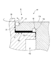
図2は、図1に示す水中アクチュエータにおけるシール構造の構成を示す断面図である。図2に示すように、まず、不動部2の台部2aにおいて外部環境41の水中と連通する箇所に凹部を設け、第1シール室11とする。この第1シール室11は、全体として見ると、細い円環状となっている。そして、ゴム系材料からなり略円環状に形成された第1シール部材31をこの第1シール室11に封入する。この場合、可動部3の軸部3aと第1シール部材31の間には、符号21で示すような第1間隙が形成される。これは、軸部3aの回転に必要な隙間であり、これ以上第1間隙21の隙間の厚みが薄いと、軸部3aの円滑な回転が損なわれることになるので、最低限の厚みの隙間は必要である。
2 is a cross-sectional view showing a configuration of a seal structure in the underwater actuator shown in FIG. As shown in FIG. 2, first, a concave portion is provided in the
第1間隙21は、その下端で水平に(図2において右方へ向かって)屈曲し、侵入防止空間13を形成する。この侵入防止空間13は、第1間隙21よりも大きな厚みを持つ空間であり、不動部2の台部2aの底面が侵入防止空間13の天井面となり、かつ、可動部3の台部3aの内部の上面が侵入防止空間13の底面となっている。侵入防止空間13の厚みは、0.5〜2.0ミリメートル程度に設定されている。この侵入防止空間13は、全体として見ると、薄い円盤状となっており、軸部3aに相当する中央部が開口した円盤状となっている。
The
上記した侵入防止空間13の内部には、充填材50が充填されている。充填材50としては、グリースが用いられいる。グリースは、JIS−K−2220に規定されるような「潤滑油中に増ちょう剤を分散させて半固体状又は固体状にしたもの」である。グリースは、いわゆる油脂材料の一つであり、水(海水、他の水溶液も含む)よりも高い粘度を有しており、かつ、疎水性(親油性)を有している。充填材50に用いるグリースとしては、JIS−K−2220に規定されているものは、すべて使用可能である。例えば、一般用グリース1種、一般用グリース2種等である。なお、充填材50として用いるグリースのちょう度番号としては、ある程度固いもの(軟らかすぎないもの)が必要であることから、ちょう度番号1号〜4号程度がよい。好ましくは、ちょう度番号2号又は3号がよい。ここに、ちょう度番号は、NLGI(米国グリース協会)で規定している番号である。ちょう度番号2号のちょう度の範囲は、265〜295であり、ちょう度番号3号のちょう度の範囲は、220〜250となっている。ここに、グリースのちょう度とは、規定の円錐を落下させ、グリースへ侵入した深さ(ミリメートル)の10倍の数値で示される。したがって、ちょう度が大きいほど、グリースが軟らかいことを示している。
The inside of the
また、侵入防止空間13の外側の端部(図2における右端)には、侵入防止空間13の外端部から上方へ食い込むような凹部が形成され、第2シール室12となっている。この第2シール室12は、全体として見ると、細い円環状となっている。そして、ゴム系材料からなり略円環状に形成された第2シール部材32がこの第2シール室12の中に封入される。
Further, a concave portion that bites upward from the outer end portion of the
第2シール室12の外端部(図2における右端部)から、図の下方へ向かって、可動部3の軸部3aと、不動部2の台部2aの間には、符号22で示すような第2間隙が形成される。これは、軸部3aの回転に必要な隙間であり、これ以上第2間隙22の隙間の厚みが薄いと、軸部3aの円滑な回転が損なわれることになるので、最低限の厚みの隙間は必要である。そして、第2間隙22の図における下端は、内部空間42に連通している。
From the outer end portion (the right end portion in FIG. 2) of the
この場合、外部環境41は水中であり、例えば海水が充満している。また、内部空間42は、空気が充満している。また、海水の圧力の方が、空気の圧力よりも大きくなっている。
In this case, the
上記のような構成により、充填材50であるグリースは、ある程度固い流動体状であるので、可動部3の軸部3aが回転した場合でも、侵入防止空間13から第1間隙21を通って外部環境41へ流出し全部が失われることはない。同様に、このグリースは、侵入防止空間13から第2間隙22を通って内部空間42へ流出し全部が失われることはない。また、グリースは粘着性に富んでいるから、侵入防止空間13に隙間無く充満するだけでなく、図2に示すように、第1間隙21や第2間隙22に一部が出ても、第1間隙21や第2間隙22の一部を隙間無く充填する。また、グリースは疎水性を有しているから、図2に示すように、第1間隙21において、外部環境41の水中から高い圧力により押し込まれてきた海水と接触した場合でも、高圧の海水がグリース内を経て内部空間42に到達することは困難である。その理由は、高圧海水がグリース内を貫通するためには、海水が侵入した孔が維持され、後続の高圧海水との間に海水が充満し、高い水圧が作用し続ける必要があるが、グリースはある程度の軟らかさを有しているから、たとえ微少な海水が押し込んできても孔は形成されず、すぐに塞がってしまうと考えられるからである。
With the above-described configuration, the grease that is the
実際に、外部環境41として約3気圧の水圧のかかる地点(水深約20メートル付近)で、NLGIちょう度番号2号のグリースを上記のような構成のシール構造4の侵入防止空間13に封入して試験をした結果、空気(約1気圧)の内部空間42への漏水は認められなかった。このため、第1実施例のシール構造4は、所用の性能を発揮できることが確認された。
Actually, the grease of
なお、本発明は、上記各実施例に限定されるものではない。上記各実施例は、例示であり、本発明の特許請求の範囲に記載された技術的思想と実質的に同一な構成を有し、同様な作用効果を奏するものは、いかなるものであっても本発明の技術的範囲に包含される。 The present invention is not limited to the above embodiments. Each of the above-described embodiments is an exemplification, and any one having substantially the same configuration as the technical idea described in the claims of the present invention and having the same operational effects can be used. It is included in the technical scope of the present invention.
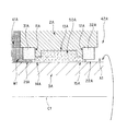
例えば、第1実施例のように屈曲したシール構造だけではなく、図3に示す第2実施例のような屈曲しない構成としても本発明は実現可能である。この第2実施例のシール構造4Aの場合も、不動部2Aの外部環境(水又は水溶液で充満された空間)41Aと連通する箇所に第1シール室11Aを設けるとともにゴム系材料からなる第1シール部材31Aを当該第1シール室11Aに封入し、不動部2Aの内部空間(空気で充満された空間)42Aと連通する箇所に第2シール室12Aを設けるとともにゴム系材料からなる第2シール部材32Aを当該第2シール室12Aに封入する。また、第1シール室11Aと第2シール室12Aにより挟まれかつ不動部2Aと可動部(直線C1を回転の中心として回転する部分)3Aに挟まれる箇所に微少厚さを有する侵入防止空間13Aを設けるとともに、外部環境41Aを構成する液体(水、又は水溶液)よりも高い粘度を有しかつ疎水性を有する油脂系材料、例えばグリースなどからなる充填材50Aを当該侵入防止空間13Aに封入するようにしてもよい。
For example, the present invention can be realized not only with a bent seal structure as in the first embodiment but also with a non-bent configuration as in the second embodiment shown in FIG. Also in the case of the seal structure 4A of the second embodiment, the
また、第1シール室と第2シール室により挟まれかつ不動部と可動部に挟まれる箇所に微少厚さを有する侵入防止空間を複数設け、その複数の侵入防止空間の中にそれぞれ充填材を充填するようにしてもよい。また、複数の侵入防止空間どうしの中間には、ゴム系材料からなる中間シール部材を、当該複数の侵入防止空間で挟まれるそれぞれの箇所に封入するようにしてもよい。 Also, a plurality of intrusion prevention spaces having a slight thickness are provided between the first seal chamber and the second seal chamber and between the immovable portion and the movable portion, and fillers are respectively provided in the intrusion prevention spaces. You may make it fill. In addition, an intermediate seal member made of a rubber-based material may be enclosed between the plurality of intrusion prevention spaces at respective locations sandwiched between the plurality of intrusion prevention spaces.
また、上記各実施例においては、外部環境として、高圧な海水を例に挙げて説明したが、外部環境としては真水又は水溶液であってもよい。また、外部環境を低圧の空気環境とし、内部空間に高圧の水又は水溶液を封入した機械の可動部においても、本発明は適用可能である。 In each of the above embodiments, high-pressure seawater is described as an example of the external environment. However, the external environment may be fresh water or an aqueous solution. The present invention can also be applied to a movable part of a machine in which the external environment is a low-pressure air environment and high-pressure water or an aqueous solution is sealed in the internal space.
また、上記した可動部の可動方向は、回転だけに限定されない。例えば、図3において可動部3Aが不動部2Aに対して、直線C1に平行な方向に往復摺動運動する場合であっても、本発明は適用可能である。
Further, the movable direction of the movable part described above is not limited to rotation. For example, the present invention is applicable even when the
本発明は、水中で作動し可動部を有する機械を製造する機械製造業等で実施可能であり、これらの産業で利用可能である。 The present invention can be implemented in a machine manufacturing industry that manufactures a machine that operates in water and has a movable part, and can be used in these industries.
1 水中アクチュエータ
2、2A 不動部
2a 台部
3、3A 可動部
3a 軸部
3b 基部
4 シール構造
11、11A 第1シール室
12、12A 第2シール室
13、13A 侵入防止空間
14A 連通空間
15A 連通空間
21、21A 第1間隙
22、22A 第2間隙
31、31A 第1シール部材
32、32A 第2シール部材
41、41A 外部環境
42、42A 内部空間
50、50A 充填材
202 不動部
203 可動部
211 シール室
221 間隙
231 Oリング
241 外部環境
242 内部空間
243、244 接続空間
A1、A2 空気
C1、C2 回転中心線
W1、W2 海水
DESCRIPTION OF SYMBOLS 1
Claims (4)
前記不動部の前記外部環境と連通する箇所に第1シール室を設けるとともにゴム系材料からなる第1シール部材を当該第1シール室に封入し、前記不動部の前記内部空間と連通する箇所に第2シール室を設けるとともにゴム系材料からなる第2シール部材を当該第2シール室に封入し、前記第1シール室と前記第2シール室により挟まれかつ前記不動部と前記可動部に挟まれる箇所に微少厚さを有する侵入防止空間を設けるとともに前記液体よりも高い粘度を有しかつ疎水性を有する油脂系材料からなる充填材を当該侵入防止空間に封入したこと
を特徴とする機械可動部密封構造。 Installed and used in an external environment filled with a liquid consisting of water or an aqueous solution, and has an internal space filled with a gas having a lower pressure than the liquid, and both the internal space and the external environment In a machine having a movable part that moves in contact, a mechanical movable part sealing structure that prevents the liquid from entering the internal space from the external environment through the movable part,
A first seal chamber is provided at a location where the stationary portion communicates with the external environment, and a first seal member made of a rubber-based material is enclosed in the first seal chamber, and at a location where the stationary portion communicates with the internal space. A second seal chamber is provided and a second seal member made of a rubber-based material is enclosed in the second seal chamber, and is sandwiched between the first seal chamber and the second seal chamber and is sandwiched between the immovable portion and the movable portion. An invasion prevention space having a very small thickness is provided at a location where the machine is movable, and a filler made of an oil-based material having a higher viscosity and hydrophobicity than the liquid is enclosed in the invasion prevention space. Partially sealed structure.
前記不動部の前記外部環境と連通する箇所に第1シール室を設けるとともにゴム系材料からなる第1シール部材を当該第1シール室に封入し、前記不動部の前記内部空間と連通する箇所に第2シール室を設けるとともにゴム系材料からなる第2シール部材を当該第2シール室に封入し、前記第1シール室と前記第2シール室により挟まれかつ前記不動部と前記可動部に挟まれる箇所に微少厚さを有する侵入防止空間を複数設けるとともにゴム系材料からなる中間シール部材を当該複数の侵入防止空間で挟まれる箇所に封入し、前記液体よりも高い粘度を有しかつ疎水性を有する油脂系材料からなる充填材を前記複数の侵入防止空間のそれぞれに封入したこと
を特徴とする機械可動部密封構造。 Installed and used in an external environment filled with a liquid consisting of water or an aqueous solution, and has an internal space filled with a gas having a lower pressure than the liquid, and both the internal space and the external environment In a machine having a movable part that moves in contact, a mechanical movable part sealing structure that prevents the liquid from entering the internal space from the external environment through the movable part,
A first seal chamber is provided at a location where the stationary portion communicates with the external environment, and a first seal member made of a rubber-based material is enclosed in the first seal chamber, and at a location where the stationary portion communicates with the internal space. A second seal chamber is provided and a second seal member made of a rubber-based material is enclosed in the second seal chamber, and is sandwiched between the first seal chamber and the second seal chamber and is sandwiched between the immovable portion and the movable portion. A plurality of intrusion prevention spaces having a very small thickness are provided at locations where an intermediate seal member made of a rubber-based material is sealed in a portion sandwiched between the plurality of intrusion prevention spaces, and has a higher viscosity than the liquid and is hydrophobic A mechanically movable part sealing structure characterized in that a filler made of an oil and fat-based material having an inside is enclosed in each of the plurality of intrusion prevention spaces.
前記不動部の前記内部空間と連通する箇所に第1シール室を設けるとともにゴム系材料からなる第1シール部材を当該第1シール室に封入し、前記不動部の前記外部環境と連通する箇所に第2シール室を設けるとともにゴム系材料からなる第2シール部材を当該第2シール室に封入し、前記第1シール室と前記第2シール室により挟まれかつ前記不動部と前記可動部に挟まれる箇所に微少厚さを有する侵入防止空間を設けるとともに前記液体よりも高い粘度を有しかつ疎水性を有する油脂系材料からなる充填材を当該侵入防止空間に封入したこと
を特徴とする機械可動部密封構造。 It is installed and used in an external environment filled with gas, and has an internal space made of water or an aqueous solution and filled with a liquid having a pressure higher than that of the gas, and both the internal space and the external environment In a machine having a movable part that moves in contact, a machine movable part sealing structure that prevents the liquid from entering the external environment from the internal space through the movable part,
A first seal chamber is provided at a location where the stationary portion communicates with the internal space, and a first seal member made of a rubber-based material is enclosed in the first seal chamber, and at a location where the stationary portion communicates with the external environment. A second seal chamber is provided and a second seal member made of a rubber-based material is enclosed in the second seal chamber, and is sandwiched between the first seal chamber and the second seal chamber and is sandwiched between the immovable portion and the movable portion. An invasion prevention space having a very small thickness is provided at a location where the machine is movable, and a filler made of an oil-based material having a higher viscosity and hydrophobicity than the liquid is enclosed in the invasion prevention space. Partially sealed structure.
前記不動部の前記内部空間と連通する箇所に第1シール室を設けるとともにゴム系材料からなる第1シール部材を当該第1シール室に封入し、前記不動部の前記外部環境と連通する箇所に第2シール室を設けるとともにゴム系材料からなる第2シール部材を当該第2シール室に封入し、前記第1シール室と前記第2シール室により挟まれかつ前記不動部と前記可動部に挟まれる箇所に微少厚さを有する侵入防止空間を複数設けるとともにゴム系材料からなる中間シール部材を当該複数の侵入防止空間で挟まれる箇所に封入し、前記液体よりも高い粘度を有しかつ疎水性を有する油脂系材料からなる充填材を当該侵入防止空間のそれぞれに封入したこと
を特徴とする機械可動部密封構造。 It is installed and used in an external environment filled with gas, and has an internal space made of water or an aqueous solution and filled with a liquid having a pressure higher than that of the gas, and both the internal space and the external environment In a machine having a movable part that moves in contact, a machine movable part sealing structure that prevents the liquid from entering the external environment from the internal space through the movable part,
A first seal chamber is provided at a location where the stationary portion communicates with the internal space, and a first seal member made of a rubber-based material is enclosed in the first seal chamber, and at a location where the stationary portion communicates with the external environment. A second seal chamber is provided and a second seal member made of a rubber-based material is enclosed in the second seal chamber, and is sandwiched between the first seal chamber and the second seal chamber and is sandwiched between the immovable portion and the movable portion. A plurality of intrusion prevention spaces having a very small thickness are provided at locations where an intermediate seal member made of a rubber-based material is sealed in a portion sandwiched between the plurality of intrusion prevention spaces, and has a higher viscosity than the liquid and is hydrophobic A structure for sealing a movable part of a machine, wherein a filler made of an oil-and-fat material having the above is enclosed in each of the intrusion prevention spaces.
Priority Applications (1)
| Application Number | Priority Date | Filing Date | Title |
|---|---|---|---|
| JP2004103599A JP2005291246A (en) | 2004-03-31 | 2004-03-31 | Machine movable part sealing structure |
Applications Claiming Priority (1)
| Application Number | Priority Date | Filing Date | Title |
|---|---|---|---|
| JP2004103599A JP2005291246A (en) | 2004-03-31 | 2004-03-31 | Machine movable part sealing structure |
Publications (1)
| Publication Number | Publication Date |
|---|---|
| JP2005291246A true JP2005291246A (en) | 2005-10-20 |
Family
ID=35324422
Family Applications (1)
| Application Number | Title | Priority Date | Filing Date |
|---|---|---|---|
| JP2004103599A Pending JP2005291246A (en) | 2004-03-31 | 2004-03-31 | Machine movable part sealing structure |
Country Status (1)
| Country | Link |
|---|---|
| JP (1) | JP2005291246A (en) |
Cited By (4)
| Publication number | Priority date | Publication date | Assignee | Title |
|---|---|---|---|---|
| KR100931982B1 (en) * | 2007-12-14 | 2009-12-15 | 주식회사 대곤코퍼레이션 | Motor waterproofing device |
| KR100931981B1 (en) * | 2007-12-14 | 2009-12-15 | 주식회사 대곤코퍼레이션 | Motor waterproofing device |
| JP2012149676A (en) * | 2011-01-18 | 2012-08-09 | Canon Inc | Bellows mechanism |
| CN118889750A (en) * | 2024-08-01 | 2024-11-01 | 中山市胜洋电机有限公司 | Waterproof structure and stepper motor housing containing the same |
-
2004
- 2004-03-31 JP JP2004103599A patent/JP2005291246A/en active Pending
Cited By (4)
| Publication number | Priority date | Publication date | Assignee | Title |
|---|---|---|---|---|
| KR100931982B1 (en) * | 2007-12-14 | 2009-12-15 | 주식회사 대곤코퍼레이션 | Motor waterproofing device |
| KR100931981B1 (en) * | 2007-12-14 | 2009-12-15 | 주식회사 대곤코퍼레이션 | Motor waterproofing device |
| JP2012149676A (en) * | 2011-01-18 | 2012-08-09 | Canon Inc | Bellows mechanism |
| CN118889750A (en) * | 2024-08-01 | 2024-11-01 | 中山市胜洋电机有限公司 | Waterproof structure and stepper motor housing containing the same |
Similar Documents
| Publication | Publication Date | Title |
|---|---|---|
| JPWO2019221226A1 (en) | Seal ring | |
| JPWO2019221228A1 (en) | Seal ring | |
| CN105917151A (en) | sealing ring | |
| TWI579463B (en) | Oil free screw compressor | |
| JP2008157453A (en) | Hydrodynamic pressure bearing device with axial pre-load applied thereto | |
| CN107005123B (en) | Electric motor with sealing system | |
| KR100500392B1 (en) | Seal ring | |
| JP6999747B2 (en) | Self-strengthening sticker | |
| JP2005291246A (en) | Machine movable part sealing structure | |
| KR20150133636A (en) | Shaft seal | |
| JP6597477B2 (en) | Valve device | |
| CN110520658B (en) | Configuration of seals | |
| JPWO2008013281A1 (en) | Seal ring | |
| JP5323964B2 (en) | U-shaped seal | |
| KR20190124586A (en) | Mechanical seal including advanced plate structure and cap structure | |
| JP2019039467A (en) | Shaft seal device | |
| JP2001141068A (en) | Sealing structure | |
| JP2012137121A (en) | Sealing device | |
| JP5273243B2 (en) | Sealing device | |
| JP2006017255A (en) | Seal mechanism | |
| KR100656823B1 (en) | Sealing structure for speed reducer | |
| CN109807928B (en) | Internal circulation type lubricating self-cleaning mechanism | |
| JP5127682B2 (en) | Lower bearing structure of the reducer output shaft | |
| JPH07269733A (en) | Ring packing | |
| JP5808681B2 (en) | Vane Seal |
Legal Events
| Date | Code | Title | Description |
|---|---|---|---|
| A977 | Report on retrieval |
Effective date: 20060421 Free format text: JAPANESE INTERMEDIATE CODE: A971007 |
|
| A131 | Notification of reasons for refusal |
Effective date: 20060530 Free format text: JAPANESE INTERMEDIATE CODE: A131 |
|
| A02 | Decision of refusal |
Effective date: 20061003 Free format text: JAPANESE INTERMEDIATE CODE: A02 |