JP2005291211A - Frequency-adjusting compressor stator blades and related methods - Google Patents
Frequency-adjusting compressor stator blades and related methods Download PDFInfo
- Publication number
- JP2005291211A JP2005291211A JP2005101052A JP2005101052A JP2005291211A JP 2005291211 A JP2005291211 A JP 2005291211A JP 2005101052 A JP2005101052 A JP 2005101052A JP 2005101052 A JP2005101052 A JP 2005101052A JP 2005291211 A JP2005291211 A JP 2005291211A
- Authority
- JP
- Japan
- Prior art keywords
- base
- compressor stator
- groove
- stator blade
- airfoil
- Prior art date
- Legal status (The legal status is an assumption and is not a legal conclusion. Google has not performed a legal analysis and makes no representation as to the accuracy of the status listed.)
- Granted
Links
Images


Classifications
-
- F—MECHANICAL ENGINEERING; LIGHTING; HEATING; WEAPONS; BLASTING
- F01—MACHINES OR ENGINES IN GENERAL; ENGINE PLANTS IN GENERAL; STEAM ENGINES
- F01D—NON-POSITIVE DISPLACEMENT MACHINES OR ENGINES, e.g. STEAM TURBINES
- F01D5/00—Blades; Blade-carrying members; Heating, heat-insulating, cooling or antivibration means on the blades or the members
- F01D5/12—Blades
- F01D5/14—Form or construction
- F01D5/16—Form or construction for counteracting blade vibration
-
- F—MECHANICAL ENGINEERING; LIGHTING; HEATING; WEAPONS; BLASTING
- F04—POSITIVE - DISPLACEMENT MACHINES FOR LIQUIDS; PUMPS FOR LIQUIDS OR ELASTIC FLUIDS
- F04D—NON-POSITIVE-DISPLACEMENT PUMPS
- F04D29/00—Details, component parts, or accessories
- F04D29/40—Casings; Connections of working fluid
- F04D29/52—Casings; Connections of working fluid for axial pumps
- F04D29/54—Fluid-guiding means, e.g. diffusers
- F04D29/541—Specially adapted for elastic fluid pumps
- F04D29/542—Bladed diffusers
-
- F—MECHANICAL ENGINEERING; LIGHTING; HEATING; WEAPONS; BLASTING
- F04—POSITIVE - DISPLACEMENT MACHINES FOR LIQUIDS; PUMPS FOR LIQUIDS OR ELASTIC FLUIDS
- F04D—NON-POSITIVE-DISPLACEMENT PUMPS
- F04D29/00—Details, component parts, or accessories
- F04D29/66—Combating cavitation, whirls, noise, vibration or the like; Balancing
- F04D29/661—Combating cavitation, whirls, noise, vibration or the like; Balancing especially adapted for elastic fluid pumps
- F04D29/668—Combating cavitation, whirls, noise, vibration or the like; Balancing especially adapted for elastic fluid pumps damping or preventing mechanical vibrations
-
- F—MECHANICAL ENGINEERING; LIGHTING; HEATING; WEAPONS; BLASTING
- F05—INDEXING SCHEMES RELATING TO ENGINES OR PUMPS IN VARIOUS SUBCLASSES OF CLASSES F01-F04
- F05D—INDEXING SCHEME FOR ASPECTS RELATING TO NON-POSITIVE-DISPLACEMENT MACHINES OR ENGINES, GAS-TURBINES OR JET-PROPULSION PLANTS
- F05D2230/00—Manufacture
- F05D2230/10—Manufacture by removing material
-
- Y—GENERAL TAGGING OF NEW TECHNOLOGICAL DEVELOPMENTS; GENERAL TAGGING OF CROSS-SECTIONAL TECHNOLOGIES SPANNING OVER SEVERAL SECTIONS OF THE IPC; TECHNICAL SUBJECTS COVERED BY FORMER USPC CROSS-REFERENCE ART COLLECTIONS [XRACs] AND DIGESTS
- Y10—TECHNICAL SUBJECTS COVERED BY FORMER USPC
- Y10T—TECHNICAL SUBJECTS COVERED BY FORMER US CLASSIFICATION
- Y10T29/00—Metal working
- Y10T29/49—Method of mechanical manufacture
- Y10T29/49316—Impeller making
- Y10T29/4932—Turbomachine making
- Y10T29/49325—Shaping integrally bladed rotor
-
- Y—GENERAL TAGGING OF NEW TECHNOLOGICAL DEVELOPMENTS; GENERAL TAGGING OF CROSS-SECTIONAL TECHNOLOGIES SPANNING OVER SEVERAL SECTIONS OF THE IPC; TECHNICAL SUBJECTS COVERED BY FORMER USPC CROSS-REFERENCE ART COLLECTIONS [XRACs] AND DIGESTS
- Y10—TECHNICAL SUBJECTS COVERED BY FORMER USPC
- Y10T—TECHNICAL SUBJECTS COVERED BY FORMER US CLASSIFICATION
- Y10T29/00—Metal working
- Y10T29/49—Method of mechanical manufacture
- Y10T29/49316—Impeller making
- Y10T29/49336—Blade making
-
- Y—GENERAL TAGGING OF NEW TECHNOLOGICAL DEVELOPMENTS; GENERAL TAGGING OF CROSS-SECTIONAL TECHNOLOGIES SPANNING OVER SEVERAL SECTIONS OF THE IPC; TECHNICAL SUBJECTS COVERED BY FORMER USPC CROSS-REFERENCE ART COLLECTIONS [XRACs] AND DIGESTS
- Y10—TECHNICAL SUBJECTS COVERED BY FORMER USPC
- Y10T—TECHNICAL SUBJECTS COVERED BY FORMER US CLASSIFICATION
- Y10T29/00—Metal working
- Y10T29/49—Method of mechanical manufacture
- Y10T29/49716—Converting
-
- Y—GENERAL TAGGING OF NEW TECHNOLOGICAL DEVELOPMENTS; GENERAL TAGGING OF CROSS-SECTIONAL TECHNOLOGIES SPANNING OVER SEVERAL SECTIONS OF THE IPC; TECHNICAL SUBJECTS COVERED BY FORMER USPC CROSS-REFERENCE ART COLLECTIONS [XRACs] AND DIGESTS
- Y10—TECHNICAL SUBJECTS COVERED BY FORMER USPC
- Y10T—TECHNICAL SUBJECTS COVERED BY FORMER US CLASSIFICATION
- Y10T29/00—Metal working
- Y10T29/49—Method of mechanical manufacture
- Y10T29/49764—Method of mechanical manufacture with testing or indicating
- Y10T29/49771—Quantitative measuring or gauging
- Y10T29/49774—Quantitative measuring or gauging by vibratory or oscillatory movement
Landscapes
- Engineering & Computer Science (AREA)
- Mechanical Engineering (AREA)
- General Engineering & Computer Science (AREA)
- Structures Of Non-Positive Displacement Pumps (AREA)
Abstract
【課題】 本発明は、振動数調整圧縮機ステータブレード及び関連する方法を提供する。
【解決手段】 基部(30)と翼形部(32)とを有する圧縮機ステータブレード(28)を調整して所望の固有振動数を得る方法は、a)圧縮機ステータブレードの固有振動数を特定する段階と、b)圧縮機ステータブレードの異なる目標固有振動数を決定する段階と、c)目標目標固有振動数が得られる量及び形状で圧縮機ステータブレード(28)の基部(30)から材料を取り除く段階とを含む。振動数調整圧縮機ステータブレードは、翼形部(32)と基部(30)とを含み、基部はほぼ直方体形状を有し、少なくとも1つの溝(34)が基部の幅寸法を横切って切削され、溝(34)は翼形部の所定の固有振動数が得られるように選択された寸法を有する。
【選択図】 図3
The present invention provides a frequency adjusted compressor stator blade and associated method.
A method of adjusting a compressor stator blade (28) having a base (30) and an airfoil (32) to obtain a desired natural frequency includes: a) determining the natural frequency of the compressor stator blade. From the base (30) of the compressor stator blade (28) in an amount and shape that results in b) determining different target natural frequencies of the compressor stator blade; and c) a target target natural frequency. Removing the material. The frequency adjusted compressor stator blade includes an airfoil (32) and a base (30), the base having a generally rectangular parallelepiped shape, and at least one groove (34) is cut across the width dimension of the base. The groove (34) has dimensions selected to provide a predetermined natural frequency of the airfoil.
[Selection] Figure 3
Description
本発明は、総括的には回転機械技術に関し、具体的には圧縮機ステータブレードの製造又は修正に関する。 The present invention relates generally to rotating machinery technology, and specifically to the manufacture or modification of compressor stator blades.
これ迄は、圧縮機ステータブレードの固有振動数の調整は、ブレードの翼形部分の形状を修正することによって行われてきた。しかしながら、翼形部分の形状を修正する必要なしに圧縮機ステータブレードの翼形部の固有振動数を修正できることが望ましいと言える。
本発明は、ブレードの翼形部分(又は、単に翼形部)を修正せずに圧縮機ステータブレードの固有振動数を調整する方法に関する。この方法によると、振動数調整が必要となった場合に、顧客の既存の圧縮機ステータブレードを続けて使用することが可能になる。これに代えて、本明細書に記載した振動数調整方法はまた、新しい圧縮機ステータブレードの製造においても同様に用いることができる。 The present invention relates to a method of adjusting the natural frequency of a compressor stator blade without modifying the airfoil portion (or simply the airfoil) of the blade. This method allows the customer's existing compressor stator blades to continue to be used when frequency adjustment becomes necessary. Alternatively, the frequency adjustment method described herein can also be used in the manufacture of new compressor stator blades as well.
本発明の例示的であるが非限定的な実施形態では、例えば基部の幅を完全に横切って延びる単一の溝を形成することによって、圧縮機ステータブレードの基部又は取付部から材料が取り除かれる。しかしながら、本発明は単一の一様な形状の溝を形成することに限定されないことを理解されたい。例えば、複数の溝によっても所望の同一結果を得ることができる。加えて、一つ又はそれ以上の溝の深さ及び/又は幅もまた、変化させることができる。従って、ステータブレード基部又は取付部の材料を適切に取り除くことによって、ブレードの翼形部基礎の剛性を変更し、それにより次に翼形の固有振動数を変更する。 In an exemplary but non-limiting embodiment of the present invention, material is removed from the base or mounting of the compressor stator blade, for example, by forming a single groove that extends completely across the width of the base. . However, it should be understood that the present invention is not limited to forming a single uniformly shaped groove. For example, the same desired result can be obtained by a plurality of grooves. In addition, the depth and / or width of one or more grooves can also be varied. Thus, by appropriately removing the material of the stator blade base or mounting, the rigidity of the blade airfoil foundation is changed, thereby changing the natural frequency of the airfoil.
従って、本発明のより広い態様では、基部と翼形部とを有する圧縮機ステータブレードを調整して所望の固有振動数を得る方法を提供し、本方法は、a)圧縮機ステータブレードの固有振動数を特定する段階と、b)圧縮機ステータブレードの異なる目標固有振動数を決定する段階と、c)目標目標固有振動数が得られる量及び形状で、圧縮機ステータブレードの基部から材料を取り除く段階とを含む。 Accordingly, in a broader aspect of the invention, a method is provided for adjusting a compressor stator blade having a base and an airfoil to obtain a desired natural frequency, the method comprising: a) the uniqueness of the compressor stator blade Identifying the frequency, b) determining different target natural frequencies of the compressor stator blade, and c) providing material from the base of the compressor stator blade in an amount and shape that provides the target target natural frequency. Removing.
別の態様では、所望の固有振動数を得るように圧縮機ステータブレードを調整する方法を提供し、圧縮機ステータブレードは、翼形部と、一対の比較的長い側面、一対の比較的短い端面、上面及び底面を備えたほぼ長方形である基部とを有しており、本方法は、a)圧縮機ステータブレードの固有振動数を特定する段階と、b)圧縮機ステータブレードの異なる目標固有振動数を決定する段階と、c)目標目標固有振動数が得られるような形状になった溝の形態で、圧縮機ステータブレードの基部から材料を取り除く段階とを含む。 In another aspect, a method is provided for adjusting a compressor stator blade to obtain a desired natural frequency, the compressor stator blade comprising an airfoil, a pair of relatively long sides, and a pair of relatively short end faces. A base that is substantially rectangular with a top surface and a bottom surface, the method comprising: a) identifying the natural frequency of the compressor stator blade; and b) different target natural vibrations of the compressor stator blade. Determining the number; and c) removing material from the base of the compressor stator blade in the form of a groove shaped to obtain a target target natural frequency.
さらに別の態様では、圧縮機ステータブレードを提供し、本圧縮機ステータブレードは、翼形部と基部とを含み、基部はほぼ直方体形状を有し、少なくとも1つの溝が基部の幅寸法を横切って切削され、溝は翼形部の所定の固有振動数が得られるように選択された寸法を有する。 In yet another aspect, a compressor stator blade is provided, the compressor stator blade including an airfoil and a base, the base having a generally rectangular parallelepiped shape, and at least one groove across the width dimension of the base. And the grooves have dimensions selected to provide a predetermined natural frequency of the airfoil.
次に、末尾に特定した図面に関連させて本発明を詳細に説明する。 The invention will now be described in detail in connection with the drawing identified at the end.
最初に図1及び図2を参照すると、公知の圧縮機ステータブレード10は、基部又は取付部12と翼形部14とを含む。基部又は取付部12は、形状がほぼ長方形であり、半径方向内面24及び半径方向外面26と共に一対の長い側面16、18及び一対の短い端面20、22を有する。基部はまた、平行四辺形の形状、すなわち平行な端面が平行な側面に対して垂直でない形状として形成することができる。これ迄は、翼形部14の固有振動数を変えるためには、翼形部自体の形状を修正しなければならなかった。
Referring initially to FIGS. 1 and 2, a known
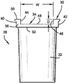
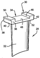
図3及び図4は、本発明の非限定的な実施形態による圧縮機ステータブレードを示す。この実施形態では、圧縮機ステータブレード28はまた、基部又は取付部30と翼形部32とを含む。ブレードの固有振動数を求めかつ目標固有振動数を特定した後に、ステータブレードは、基部又は取付部30から材料を選択的に取り除くことによって修正される。具体的には、単一の幅広の溝34が、切削又は機械加工によって基部又は取付部内に形成され、この溝は、基部又は取付部の幅を完全に横切って、すなわち端面40、42と平行に側面36から側面38まで延びる。溝の幅は、実質的に翼形部32の翼弦方向長さ全体にわたっていることが分かる。このケースでは、溝34は、平行な側面44、46と平坦な底又は底面48を有する。底面48は、基部又は取付部30の半径方向内面50及び半径方向外面52に対して平行である。
3 and 4 illustrate a compressor stator blade according to a non-limiting embodiment of the present invention. In this embodiment, the
基部又は取付部から取り除かれる材料の量が所望の固有振動数に応じて決まることは、当業者には明らかであろう。従って、溝の幅「W」及び深さ「D」は、目標固有振動数を得るための必要に応じて変えることができる。加えて、溝34の側面44、46は、直線状又は平行である必要はなく、また溝の深さ「D」は、溝の平坦な底面48にわたって変化させることができる。例えば、面44、46は、対向させて湾曲(凸状又は凹状のいずれか)させることができ、また深さDは、溝の長さ及び/又は幅にわたって線形又は非線形に変化させることができる。所望の固有振動数はまた、同一の又は異なる大きさ及び形状の1つ又はそれ以上の付加的な溝を形成することによっても得ることができる。
It will be apparent to those skilled in the art that the amount of material removed from the base or mounting depends on the desired natural frequency. Thus, the groove width “W” and depth “D” can be varied as needed to obtain the target natural frequency. In addition, the
翼形部の固有振動数を調整する目的でステータブレードの基部又は取付部から材料を取り除くことは、既存の圧縮機ステータブレードを改造するだけでなく、圧縮機ステータブレードの初期設計及び製造にも使用することができる概念である。既存の圧縮機ステータブレードに本発明を利用することができることにより、振動数に関する問題に対して、修正した翼形部形状を有する新しいステータブレードを製造するような通常のサイクルに比べて、比較的早いハードウェアの解決が得られる。 Removing material from the base or mounting of the stator blades to adjust the airfoil natural frequency not only modifies the existing compressor stator blades, but also in the initial design and manufacture of the compressor stator blades. It is a concept that can be used. The ability to use the present invention with existing compressor stator blades allows for relatively low frequency problems compared to conventional cycles such as manufacturing new stator blades with modified airfoil shapes. Get a fast hardware solution.
現在最も実用的でかつ好ましい実施形態であると考えられるものに関して本発明を説明してきたが、本発明は開示した実施形態に限定されるものではなく、また特許請求の範囲に記載した参照符号は、本発明の技術的範囲を狭めるのではなく、本発明をより容易に理解するためのものであることを理解されたい。 Although the present invention has been described with respect to what is presently considered to be the most practical and preferred embodiments, the invention is not limited to the disclosed embodiments, and reference signs in the claims are not It should be understood that the present invention is not intended to narrow the technical scope of the present invention but rather to more easily understand the present invention.
28 圧縮機ステータブレード
30 基部
32 翼形部
34 溝
36、38 基部の側面
40、42 基部の端面
44、46 溝の側面
48 溝の底面
50 基部の半径方向内面
52 基部の半径方向外面
D 溝の深さ
W 溝の幅
28 Compressor Stator Blade 30
Claims (10)
a)前記圧縮機ステータブレードの固有振動数を特定する段階と、
b)前記圧縮機ステータブレードの異なる目標固有振動数を決定する段階と、
c)前記目標目標固有振動数が得られる量及び形状で、前記圧縮機ステータブレード(28)の基部(30)から材料を取り除く段階と、
を含む方法。 A method of adjusting a compressor stator blade (28) having a base (30) and an airfoil (32) to obtain a desired natural frequency,
a) identifying the natural frequency of the compressor stator blade;
b) determining different target natural frequencies of the compressor stator blade;
c) removing material from the base (30) of the compressor stator blade (28) in an amount and shape that provides the target target natural frequency;
Including methods.
Applications Claiming Priority (2)
| Application Number | Priority Date | Filing Date | Title |
|---|---|---|---|
| US10/814,221 | 2004-04-01 | ||
| US10/814,221 US7024744B2 (en) | 2004-04-01 | 2004-04-01 | Frequency-tuned compressor stator blade and related method |
Publications (2)
| Publication Number | Publication Date |
|---|---|
| JP2005291211A true JP2005291211A (en) | 2005-10-20 |
| JP4711717B2 JP4711717B2 (en) | 2011-06-29 |
Family
ID=35034279
Family Applications (1)
| Application Number | Title | Priority Date | Filing Date |
|---|---|---|---|
| JP2005101052A Expired - Fee Related JP4711717B2 (en) | 2004-04-01 | 2005-03-31 | Frequency-adjusting compressor stator blades and related methods |
Country Status (4)
| Country | Link |
|---|---|
| US (1) | US7024744B2 (en) |
| JP (1) | JP4711717B2 (en) |
| CN (1) | CN100419218C (en) |
| DE (1) | DE102005014074A1 (en) |
Families Citing this family (23)
| Publication number | Priority date | Publication date | Assignee | Title |
|---|---|---|---|---|
| DE102005006414A1 (en) * | 2005-02-12 | 2006-08-24 | Mtu Aero Engines Gmbh | A method of machining an integrally bladed rotor |
| GB0601837D0 (en) * | 2006-01-31 | 2006-03-08 | Rolls Royce Plc | An aerofoil assembly and a method of manufacturing an aerofoil assembly |
| US7507073B2 (en) * | 2006-02-24 | 2009-03-24 | General Electric Company | Methods and apparatus for assembling a steam turbine bucket |
| US7618234B2 (en) * | 2007-02-14 | 2009-11-17 | Power System Manufacturing, LLC | Hook ring segment for a compressor vane |
| KR20090087930A (en) * | 2007-06-22 | 2009-08-18 | 미츠비시 쥬고교 가부시키가이샤 | Jeongikhwan and Axial Flow Compressor Using the Same |
| US7854583B2 (en) * | 2007-08-08 | 2010-12-21 | Genral Electric Company | Stator joining strip and method of linking adjacent stators |
| DE102007059155A1 (en) * | 2007-12-06 | 2009-06-10 | Rolls-Royce Deutschland Ltd & Co Kg | Process for the manufacture of integrally constructed impellers for compressors and turbines |
| US20100166550A1 (en) * | 2008-12-31 | 2010-07-01 | Devangada Siddaraja M | Methods, systems and/or apparatus relating to frequency-tuned turbine blades |
| US8534965B2 (en) * | 2009-04-17 | 2013-09-17 | General Electric Company | Apparatus and tools for use with compressors |
| US8381379B2 (en) * | 2009-04-17 | 2013-02-26 | General Electric Company | Apparatus and tools for use with compressors |
| CA2761208C (en) | 2010-12-08 | 2019-03-05 | Pratt & Whitney Canada Corp. | Blade disk arrangement for blade frequency tuning |
| US8757962B2 (en) * | 2011-06-16 | 2014-06-24 | General Electric Company | System and method for adjusting a shroud block in a casing |
| CN104265681B (en) * | 2014-08-01 | 2016-08-31 | 中国人民解放军第五七一九工厂 | The method changing blade self natural frequency |
| CN104728170A (en) * | 2015-03-25 | 2015-06-24 | 北京华清燃气轮机与煤气化联合循环工程技术有限公司 | Gas compressor frequency adjustment structure |
| US10215194B2 (en) | 2015-12-21 | 2019-02-26 | Pratt & Whitney Canada Corp. | Mistuned fan |
| CA2958459C (en) | 2016-02-19 | 2025-07-08 | Pratt & Whitney Canada Corp. | Compressor rotor for supersonic flutter and/or resonant stress mitigation |
| US10533581B2 (en) | 2016-12-09 | 2020-01-14 | United Technologies Corporation | Stator with support structure feature for tuned airfoil |
| US10458436B2 (en) | 2017-03-22 | 2019-10-29 | Pratt & Whitney Canada Corp. | Fan rotor with flow induced resonance control |
| US10480535B2 (en) | 2017-03-22 | 2019-11-19 | Pratt & Whitney Canada Corp. | Fan rotor with flow induced resonance control |
| US10823203B2 (en) | 2017-03-22 | 2020-11-03 | Pratt & Whitney Canada Corp. | Fan rotor with flow induced resonance control |
| US10876417B2 (en) | 2017-08-17 | 2020-12-29 | Raytheon Technologies Corporation | Tuned airfoil assembly |
| CN113606189B (en) * | 2021-08-23 | 2024-07-02 | 中国联合重型燃气轮机技术有限公司 | Compressor blade, method for determining size of frequency modulation notch of compressor blade, compressor and gas turbine |
| US12043368B2 (en) | 2022-03-23 | 2024-07-23 | General Electric Company | Rotating airfoil assembly |
Citations (4)
| Publication number | Priority date | Publication date | Assignee | Title |
|---|---|---|---|---|
| JPS61192597U (en) * | 1985-05-24 | 1986-11-29 | ||
| JPS6487805A (en) * | 1987-08-12 | 1989-03-31 | Snecma | Manufacture of vane row of stator guide vane of compressor or turbine and vane and vane row formed by said method |
| JPH09105310A (en) * | 1995-06-02 | 1997-04-22 | United Technol Corp <Utc> | Flow orientation control element for gas-turbine engine and axial compressor |
| JP2001012390A (en) * | 1999-06-24 | 2001-01-16 | Hitachi Ltd | Gas turbine compressor blades |
Family Cites Families (16)
| Publication number | Priority date | Publication date | Assignee | Title |
|---|---|---|---|---|
| US3326523A (en) * | 1965-12-06 | 1967-06-20 | Gen Electric | Stator vane assembly having composite sectors |
| FR2282550A1 (en) * | 1974-08-21 | 1976-03-19 | Shur Lok International Sa | MONOBLOC CASING COMPRESSOR STATOR |
| US4118147A (en) * | 1976-12-22 | 1978-10-03 | General Electric Company | Composite reinforcement of metallic airfoils |
| US5022818A (en) * | 1989-02-21 | 1991-06-11 | Westinghouse Electric Corp. | Compressor diaphragm assembly |
| US5123813A (en) * | 1991-03-01 | 1992-06-23 | General Electric Company | Apparatus for preloading an airfoil blade in a gas turbine engine |
| FR2702242B1 (en) * | 1993-03-03 | 1995-04-07 | Snecma | Free blades stage at one end. |
| US5939006A (en) * | 1995-06-28 | 1999-08-17 | General Electric Company | Method for forming a composite airfoil structure |
| US5720597A (en) * | 1996-01-29 | 1998-02-24 | General Electric Company | Multi-component blade for a gas turbine |
| JPH1054204A (en) * | 1996-05-20 | 1998-02-24 | General Electric Co <Ge> | Multi-component wing for gas turbine |
| US5931641A (en) * | 1997-04-25 | 1999-08-03 | General Electric Company | Steam turbine blade having areas of different densities |
| US6042338A (en) * | 1998-04-08 | 2000-03-28 | Alliedsignal Inc. | Detuned fan blade apparatus and method |
| DE19905501B4 (en) | 1999-02-10 | 2005-05-19 | MediGene AG, Gesellschaft für molekularbiologische Kardiologie und Onkologie | A method of producing a recombinant adeno-associated virus, suitable compositions therefor, and use for the manufacture of a medicament |
| US6331100B1 (en) * | 1999-12-06 | 2001-12-18 | General Electric Company | Doubled bowed compressor airfoil |
| US6398489B1 (en) * | 2001-02-08 | 2002-06-04 | General Electric Company | Airfoil shape for a turbine nozzle |
| US6604285B2 (en) * | 2001-06-07 | 2003-08-12 | General Electric Company | Method and apparatus for electronically determining nozzle throat area and harmonics |
| US6607358B2 (en) * | 2002-01-08 | 2003-08-19 | General Electric Company | Multi-component hybrid turbine blade |
-
2004
- 2004-04-01 US US10/814,221 patent/US7024744B2/en not_active Expired - Fee Related
-
2005
- 2005-03-23 DE DE102005014074A patent/DE102005014074A1/en not_active Withdrawn
- 2005-03-31 JP JP2005101052A patent/JP4711717B2/en not_active Expired - Fee Related
- 2005-04-01 CN CNB2005100626302A patent/CN100419218C/en not_active Expired - Fee Related
Patent Citations (4)
| Publication number | Priority date | Publication date | Assignee | Title |
|---|---|---|---|---|
| JPS61192597U (en) * | 1985-05-24 | 1986-11-29 | ||
| JPS6487805A (en) * | 1987-08-12 | 1989-03-31 | Snecma | Manufacture of vane row of stator guide vane of compressor or turbine and vane and vane row formed by said method |
| JPH09105310A (en) * | 1995-06-02 | 1997-04-22 | United Technol Corp <Utc> | Flow orientation control element for gas-turbine engine and axial compressor |
| JP2001012390A (en) * | 1999-06-24 | 2001-01-16 | Hitachi Ltd | Gas turbine compressor blades |
Also Published As
| Publication number | Publication date |
|---|---|
| JP4711717B2 (en) | 2011-06-29 |
| US20050220615A1 (en) | 2005-10-06 |
| CN1690366A (en) | 2005-11-02 |
| US7024744B2 (en) | 2006-04-11 |
| DE102005014074A1 (en) | 2005-10-20 |
| CN100419218C (en) | 2008-09-17 |
Similar Documents
| Publication | Publication Date | Title |
|---|---|---|
| JP4711717B2 (en) | Frequency-adjusting compressor stator blades and related methods | |
| JP2007046608A (en) | Gas turbine engine rotor, gas turbine engine, and gas turbine engine fan adjusting method | |
| JPH08105301A (en) | Arrangement for mitigating stress peaks in turbine blade anchors, including the so-called "fir tree-footed" roots | |
| US20190178262A1 (en) | Flow Machine And Method For The Production Thereof | |
| US7784181B2 (en) | Processing method of a semi-processed product for the production of a rotor equipped with a series of blades integral therewith | |
| EP2862658A1 (en) | Method for manufacturing compressor impeller and compressor impeller | |
| JP2011020252A (en) | Chip saw | |
| JP5734392B2 (en) | Impeller, impeller cutting jig, and impeller machining method | |
| CN102330572B (en) | Rotor of a turbomachine | |
| JP2000505001A (en) | Method for preventing or reducing the formation of magnetism in two adjacently positioned saw teeth rotating in opposite directions, and apparatus for utilizing this method | |
| US10427213B2 (en) | Turbine blade with sectioned pins and method of making same | |
| US20100018377A1 (en) | Universal 3-TAB center for a cutting disc | |
| EP0155314B1 (en) | Saw blade or blank having self plugging stress relief means | |
| JPH10508262A (en) | Saw blade | |
| CN105637182B (en) | Turbine blades and gas turbines | |
| EP2669477B1 (en) | Shroud for airfoils | |
| JP2006231480A (en) | Saw blade | |
| JPS6397803A (en) | Fixed part structure of turbine blade | |
| JP2007090486A (en) | Hole cutter | |
| JP2006097524A (en) | Manufacturing method for blade | |
| JP2008213127A (en) | Tab groove processing method | |
| CN112895175A (en) | Cutting knife wheel | |
| JP5662201B2 (en) | Saw blade | |
| JP2007160416A (en) | Cutting blade | |
| JP2019098605A (en) | Scribing wheel |
Legal Events
| Date | Code | Title | Description |
|---|---|---|---|
| A621 | Written request for application examination |
Free format text: JAPANESE INTERMEDIATE CODE: A621 Effective date: 20080327 |
|
| A131 | Notification of reasons for refusal |
Free format text: JAPANESE INTERMEDIATE CODE: A131 Effective date: 20101102 |
|
| A521 | Request for written amendment filed |
Free format text: JAPANESE INTERMEDIATE CODE: A523 Effective date: 20110201 |
|
| RD02 | Notification of acceptance of power of attorney |
Free format text: JAPANESE INTERMEDIATE CODE: A7422 Effective date: 20110201 |
|
| RD04 | Notification of resignation of power of attorney |
Free format text: JAPANESE INTERMEDIATE CODE: A7424 Effective date: 20110201 |
|
| A01 | Written decision to grant a patent or to grant a registration (utility model) |
Free format text: JAPANESE INTERMEDIATE CODE: A01 Effective date: 20110222 |
|
| A61 | First payment of annual fees (during grant procedure) |
Free format text: JAPANESE INTERMEDIATE CODE: A61 Effective date: 20110322 |
|
| LAPS | Cancellation because of no payment of annual fees |