JP2005291201A - High recovery sonic gas valve - Google Patents
High recovery sonic gas valve Download PDFInfo
- Publication number
- JP2005291201A JP2005291201A JP2005062534A JP2005062534A JP2005291201A JP 2005291201 A JP2005291201 A JP 2005291201A JP 2005062534 A JP2005062534 A JP 2005062534A JP 2005062534 A JP2005062534 A JP 2005062534A JP 2005291201 A JP2005291201 A JP 2005291201A
- Authority
- JP
- Japan
- Prior art keywords
- valve
- inlet
- nozzle throat
- nozzle
- outlet
- Prior art date
- Legal status (The legal status is an assumption and is not a legal conclusion. Google has not performed a legal analysis and makes no representation as to the accuracy of the status listed.)
- Granted
Links
- 238000011084 recovery Methods 0.000 title abstract 2
- 238000011144 upstream manufacturing Methods 0.000 claims abstract description 25
- 238000003754 machining Methods 0.000 claims description 8
- 239000000446 fuel Substances 0.000 claims description 6
- 238000013459 approach Methods 0.000 claims description 4
- 230000007704 transition Effects 0.000 claims description 4
- 230000007423 decrease Effects 0.000 claims description 3
- 239000012530 fluid Substances 0.000 claims 8
- 230000000320 anti-stroke effect Effects 0.000 claims 1
- 238000013461 design Methods 0.000 abstract description 6
- 230000000694 effects Effects 0.000 abstract description 5
- 238000000034 method Methods 0.000 description 6
- 230000004323 axial length Effects 0.000 description 3
- 238000009530 blood pressure measurement Methods 0.000 description 3
- 238000012986 modification Methods 0.000 description 3
- 230000004048 modification Effects 0.000 description 3
- 230000006870 function Effects 0.000 description 2
- 238000004519 manufacturing process Methods 0.000 description 2
- 238000000926 separation method Methods 0.000 description 2
- 230000002411 adverse Effects 0.000 description 1
- 230000009286 beneficial effect Effects 0.000 description 1
- 230000000903 blocking effect Effects 0.000 description 1
- 238000009529 body temperature measurement Methods 0.000 description 1
- 230000008859 change Effects 0.000 description 1
- 238000005516 engineering process Methods 0.000 description 1
- 230000002349 favourable effect Effects 0.000 description 1
- 238000009434 installation Methods 0.000 description 1
- 239000007788 liquid Substances 0.000 description 1
- 239000000463 material Substances 0.000 description 1
- 230000007246 mechanism Effects 0.000 description 1
- 230000008569 process Effects 0.000 description 1
- 238000012545 processing Methods 0.000 description 1
- 230000009467 reduction Effects 0.000 description 1
- 238000012546 transfer Methods 0.000 description 1
Images
Classifications
-
- F—MECHANICAL ENGINEERING; LIGHTING; HEATING; WEAPONS; BLASTING
- F16—ENGINEERING ELEMENTS AND UNITS; GENERAL MEASURES FOR PRODUCING AND MAINTAINING EFFECTIVE FUNCTIONING OF MACHINES OR INSTALLATIONS; THERMAL INSULATION IN GENERAL
- F16K—VALVES; TAPS; COCKS; ACTUATING-FLOATS; DEVICES FOR VENTING OR AERATING
- F16K1/00—Lift valves or globe valves, i.e. cut-off apparatus with closure members having at least a component of their opening and closing motion perpendicular to the closing faces
- F16K1/32—Details
- F16K1/34—Cutting-off parts, e.g. valve members, seats
- F16K1/36—Valve members
- F16K1/38—Valve members of conical shape
-
- F—MECHANICAL ENGINEERING; LIGHTING; HEATING; WEAPONS; BLASTING
- F16—ENGINEERING ELEMENTS AND UNITS; GENERAL MEASURES FOR PRODUCING AND MAINTAINING EFFECTIVE FUNCTIONING OF MACHINES OR INSTALLATIONS; THERMAL INSULATION IN GENERAL
- F16K—VALVES; TAPS; COCKS; ACTUATING-FLOATS; DEVICES FOR VENTING OR AERATING
- F16K1/00—Lift valves or globe valves, i.e. cut-off apparatus with closure members having at least a component of their opening and closing motion perpendicular to the closing faces
- F16K1/32—Details
- F16K1/52—Means for additional adjustment of the rate of flow
-
- F—MECHANICAL ENGINEERING; LIGHTING; HEATING; WEAPONS; BLASTING
- F16—ENGINEERING ELEMENTS AND UNITS; GENERAL MEASURES FOR PRODUCING AND MAINTAINING EFFECTIVE FUNCTIONING OF MACHINES OR INSTALLATIONS; THERMAL INSULATION IN GENERAL
- F16K—VALVES; TAPS; COCKS; ACTUATING-FLOATS; DEVICES FOR VENTING OR AERATING
- F16K47/00—Means in valves for absorbing fluid energy
Landscapes
- Engineering & Computer Science (AREA)
- General Engineering & Computer Science (AREA)
- Mechanical Engineering (AREA)
- Lift Valve (AREA)
- Measuring Volume Flow (AREA)
- Details Of Valves (AREA)
Abstract
【課題】従来設計の場合より低い圧力比で音速流れを達成するガス弁を提供すること。
【解決手段】入口流れが横向きで、出口流れに直交して入ってくる高リカバリ音速ガス弁が提供される。この構成は、ノズルおよびディフューザの軸に直交して入ってくる入口流れの影響を打ち消す。入口通路は、流れがノズルおよびディフューザの中心線に沿って入るように湾曲している。このノズルは輪郭成形され、上流の流れの障害を提供する。ディフューザは、その面積勾配が、ノズルスロートにおける小さな正の値から、最大値を経て、最終的にノズル出口の手前でほぼゼロへ大きく落ち込むまで変化するように、輪郭成形される。ディフューザはほぼ円筒形であり、弁の出口フランジを越えて延在して、隣接する配管内へ突出してもよい。
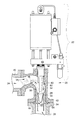
【選択図】図2
To provide a gas valve that achieves a sonic flow at a lower pressure ratio than in a conventional design.
A high recovery sonic gas valve is provided in which the inlet flow is sideways and enters orthogonally to the outlet flow. This configuration counteracts the effects of the inlet flow entering perpendicular to the nozzle and diffuser axes. The inlet passage is curved so that the flow enters along the centerline of the nozzle and diffuser. This nozzle is contoured and provides an upstream flow obstruction. The diffuser is contoured so that its area gradient changes from a small positive value at the nozzle throat, through a maximum value, and finally to a large drop to almost zero before the nozzle exit. The diffuser is generally cylindrical and may extend beyond the outlet flange of the valve and protrude into the adjacent piping.
[Selection] Figure 2
Description
本発明は一般的にはガス弁に関し、より詳細には音速ガス弁に関する。 The present invention relates generally to gas valves, and more particularly to sonic gas valves.
多くの産業において質量流量の精確な制御は必要条件である。例えば、装置産業では気体流が制御されている。ガスタービン産業では、ガスタービンへ送り込む燃料を計量するために、質量流量が用いられている。質量流量は、次式から判定される。
上流側圧力と温度との測定値が、気体密度を導くのに用いられる。亜音速弁内の速度を計測するには、下流側圧力も計測し、上流側と下流側の圧力の圧力差に基づいて速度が導き出される。しかし、この下流側圧力の測定は、上流側および下流側の両センサの使用のため流量制御の精度および信頼性を低下させる。 Upstream pressure and temperature measurements are used to derive the gas density. In order to measure the speed in the subsonic valve, the downstream pressure is also measured, and the speed is derived based on the pressure difference between the upstream pressure and the downstream pressure. However, this downstream pressure measurement reduces the accuracy and reliability of the flow control due to the use of both upstream and downstream sensors.
精度および信頼性の低下の結果、業界は、弁のノズルのスロート(最も狭い部分)内での速度がマッハ1.0である音速ガス弁を開発した。スロート内での気体速度がマッハ1.0である場合、下流側圧力信号はノズルスロートを通って上流へ伝播できない。というのは、圧力信号は音速より速く伝わり得ないからである。こうしたことから得られる結果の一つが、ノズルスロート内での速度がマッハ1.0である場合に、ノズルへ流入する上流側流れ(フロー)は、下流側圧力の影響を受けないことである。従って、下流側圧力が低下した場合であっても、ノズルスロート内での速度は影響を受けない。その結果、速度決定にとって下流側圧力測定はもはや不必要である。 As a result of reduced accuracy and reliability, the industry has developed a sonic gas valve with a Mach 1.0 velocity in the throat (narrowest part) of the valve nozzle. If the gas velocity in the throat is Mach 1.0, the downstream pressure signal cannot propagate upstream through the nozzle throat. This is because the pressure signal cannot travel faster than the speed of sound. One of the results obtained from this is that when the velocity in the nozzle throat is Mach 1.0, the upstream flow flowing into the nozzle is not affected by the downstream pressure. Therefore, even if the downstream pressure is reduced, the speed in the nozzle throat is not affected. As a result, downstream pressure measurements are no longer necessary for speed determination.
音速流れ(すなわち、気体速度はマッハ1.0である)をよりた易く達成できるのは、弁の入口側配管と出口側配管とが一直線になっている(例えば、両中心線が共通直線である)場合である。しかし、弁の入口側配管および出口側配管は、その多くの設置で一直線にはならない。入口側配管が出口側配管に対して直交するバルブでは、気体のフローパターンは入口から出口へ基本的に90度旋回する。吐出配管の中心線からというより側部から入ってくる流れが、弁内の流れをノズルスロートの周りで不均一にしてしまう。その結果、音速流れの達成はより困難になり、音速流れを達成するためには、より高い圧力降下が要求される。この高い圧力降下は著しいエネルギー損失の原因になる可能性があり、またシステムの効率に悪影響を及ぼす可能性がある。 The sonic flow (that is, the gas velocity is Mach 1.0) can be more easily achieved because the inlet side piping and the outlet side piping of the valve are in a straight line (for example, both center lines are a common straight line). There is a case. However, the inlet side piping and the outlet side piping of the valve are not aligned in many installations. In a valve in which the inlet side pipe is orthogonal to the outlet side pipe, the gas flow pattern basically turns 90 degrees from the inlet to the outlet. The flow coming in from the side rather than from the center line of the discharge pipe makes the flow in the valve non-uniform around the nozzle throat. As a result, achieving sonic flow becomes more difficult and higher pressure drops are required to achieve sonic flow. This high pressure drop can cause significant energy loss and can adversely affect the efficiency of the system.
本発明は、可変面積臨界(音速)ベンチュリ設計において、従来設計の場合より低い圧力比(P1/P2)で音速流れを達成するガス弁の設計を提供する。この弁の設計は、入口通路のために湾曲流路を設け、ノズル流れ領域環状部の円周まわりの各地点にごく類似した流れ条件を生み出す、より一様な態様で、入口側流れをノズル領域へ強制的に送り込む。 The present invention provides a gas valve design that achieves sonic flow in a variable area critical (sonic) venturi design with a lower pressure ratio (P1 / P2) than in conventional designs. This valve design provides a curved flow path for the inlet passage and produces a flow condition very similar to each point around the circumference of the nozzle flow region annulus in a more uniform manner. Force into the area.
本発明はさらに、流れを真直ぐにするために、ノズルスロート上流に配置する細まり形状の絞りを提供する。この細まり形状絞りは、その面積勾配がほぼゼロ(例えば、僅かに負の勾配)で始まり、ノズルスロートへ近づくにつれて負の勾配が増える。 The present invention further provides a narrowed throttle located upstream of the nozzle throat to straighten the flow. This narrow shaped aperture starts with an area gradient of approximately zero (eg, a slightly negative gradient), and the negative gradient increases as it approaches the nozzle throat.
ノズル下流のディフューザの形状は、面積勾配が小さな正の値で始まって大きくなり、最大値まで増加した後、ディユーザの出口で小さくなり、そこでの流路の形状がほぼ円筒形であるようになされている。ディフューザ部分の最大直径位置の軸方向長さの一部分は面積勾配がほぼゼロである。一実施の形態において、装着時にこのディフューザ部分は延在して弁の出口フランジを通って、隣接する配管内へ突出する。 The shape of the diffuser downstream of the nozzle is such that the area gradient starts with a small positive value and increases, then increases to the maximum value and then decreases at the exit of the diffuser, where the channel shape is approximately cylindrical. Has been made. A portion of the axial length of the maximum diameter position of the diffuser portion has a substantially zero area gradient. In one embodiment, when installed, the diffuser portion extends and projects through the valve outlet flange into the adjacent piping.
本発明のこれら利点および他の利点、ならびに発明上の更なる特徴は、ここに記載の本発明の説明から明らかになろう。 These and other advantages of the invention, as well as additional inventive features, will be apparent from the description of the invention provided herein.
本発明を特定の好ましい実施の形態に関連して説明するが、本発明をかかる実施の形態に限定する意図はない。反面、添付の請求項で定義される発明の精神および範囲に包含されるすべての代替、変形、および均等物を含むものとする。 While the invention will be described in connection with certain preferred embodiments, there is no intent to limit the invention to such embodiments. On the contrary, it is intended to include all alternatives, modifications, and equivalents included within the spirit and scope of the invention as defined by the appended claims.
本発明は、弁ノズルおよびディフューザの軸に直交して入ってくる入口流れへ及ぼす影響を打ち消すか大きく減らす、気体(空気を含む)の流れおよび/または工業用もしくはガスタービン用の燃料の流れを制御するガス制御弁、または、他の流量制御システムを提供する。臨界圧力比を最適化する方策のいくつかを説明する必要があろう。弁の臨界圧力比(P1/P2)は、入口圧力(P1)の出口圧力(P2)に対する比として定義され、この出口圧力での弁の流量は、音速流量の数%下方まで降下する。何れのガス弁も、その圧力比(P1/P2)が略2.0を超える(気体特性に依存する)のに伴って、弁のスロート内ではマッハ1.0の音速流れをもたらすことになる。先に述べた特徴を用いてここで記載する弁は、一実施の形態において略1.04以上の圧力比(P1/P2)でノズルスロート全体にわたって音速流れを提供する。こうした手法のいくつかを、液体弁を含む他の種類の弁に適用して、損失を減らすとともに、最大流量を高めるようにしてもよい。ここで説明する実施の形態は、流路断面がほぼ円形であり、弁内の流路には90度のベンドを有する。かかる特徴および方策は、長方形断面のような他の流路断面形状、そして真直な流路、あるいは、入口と出口の両フランジが整列するとともにノズル中心線に直交する典型的な玉型弁設計のような他の流路形状、および亜音速弁にも適用できる。 The present invention reduces gas (including air) flow and / or fuel flow for industrial or gas turbines, which counteracts or greatly reduces the effect on inlet flow that is orthogonal to the axis of the valve nozzle and diffuser. A gas control valve or other flow control system to control is provided. Some measures to optimize the critical pressure ratio will need to be explained. The critical pressure ratio of the valve (P1 / P2) is defined as the ratio of the inlet pressure (P1) to the outlet pressure (P2), and the flow rate of the valve at this outlet pressure drops to a few percent below the sonic flow rate. Any gas valve will produce a Mach 1.0 sonic flow in the throat of the valve as its pressure ratio (P1 / P2) exceeds approximately 2.0 (depending on gas characteristics). . The valves described herein using the features described above provide sonic flow across the nozzle throat in one embodiment with a pressure ratio (P1 / P2) of approximately 1.04 or greater. Some of these techniques may be applied to other types of valves, including liquid valves, to reduce losses and increase maximum flow. In the embodiment described here, the cross section of the flow path is substantially circular, and the flow path in the valve has a bend of 90 degrees. Such features and strategies can be found in other channel cross-sectional shapes, such as rectangular cross-sections, and straight flow paths, or in the typical ball valve design where the inlet and outlet flanges are aligned and perpendicular to the nozzle centerline. The present invention can also be applied to other flow path shapes and subsonic valves.
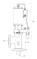
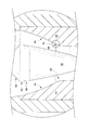
ここで、同様な符号が同様な要素を指す各図面を参照すると、本発明によるガス制御弁20の例示の実施の形態が図1に示されている。以下の説明から明らかになるであろうが、このガス制御弁20は、弁ノズルおよびディフューザの軸に直交して入ってくる入口流れの影響を最小限にするか、打ち消すかする弁である。
Referring now to the drawings wherein like numerals refer to like elements, an exemplary embodiment of a
図1乃至図4を参照すると、弁本体20は、気体入口24と、気体出口26と、弁ニードル30用のノズルスロート28とを有する。アクチュエータ22は、ノズルスロート28に対する弁ニードル30の動きを制御する何れの種類のアクチュエータであってもよい。アクチュエータそのものは広く周知であり、ここで詳細に検討を加える必要はない。弁ニードル30は、所望の、気体流れ対アクチュエータのピストンストローク(すなわち、位置)を提供するよう成形された輪郭面32を持っている。矢印34で示す流路は、入口通路36における湾曲流路であって、入口流れを強制的にノズル38へ、より一様に入るようにする。ノズル38は細まり流れ(converging flow)を生じ、そこでは流路断面積が流れ方向に沿って減少していく。この湾曲流路は、ノズルスロート28の上流にある位置で、ノズル中心線に平行な方向へ流れを変えることにより、ノズルおよびディフューザ軸に直交する入口流れの影響を打ち消す手助けをする。
1 to 4, the
入口流路の流れ断面積は、上流の入口側配管の断面積より小さな流れ面積を持ち、これにより、流れは強制的に所望の方向へ向けられる。より大きな断面積の入口流路も使用できるが、流れがあまり好ましくない経路に沿うことを許容する可能性がある。より小さな流れの断面積を適用して、音速弁ではないガス弁を含め他の種類の弁での損失を著しく減らすことができる。 The flow cross-sectional area of the inlet channel has a smaller flow area than the cross-sectional area of the upstream inlet-side piping, thereby forcing the flow in the desired direction. Larger cross-sectional inlet channels can also be used, but may allow flow to follow a less favorable path. Smaller flow cross-sectional areas can be applied to significantly reduce losses in other types of valves, including gas valves that are not sonic valves.
小断面積の入口流路は、入口流路が出口フランジ42からできるだけ離れるような、流路が入口側配管40に対して偏心する態様で、上流配管40に隣接して始まる(図2を参照)。これにより入口流路に要求される曲率が縮小されるので、流れがノズル中心線に沿ってノズル領域へ入ることが可能になる。
The small cross-sectional area inlet flow path begins adjacent to the
一実施の形態では、入口流路の断面は非円形であり、それはほぼ楕円形であるか、または流れ方向に直交して計測される曲率半径が、流れ方向に平行して計測される小さい方の曲率半径を持つ流路の側の方が小さくなるような形である(図8を参照)。どちらの場合であっても、大きい方の寸法が、ノズル中心線の軸に直交する楕円の長軸に相当する流路を測ることになる。このことは、ノズルスロート28の上流の位置で、ノズル中心線に平行な方向へ流れを変える更なる手助けとなる。
In one embodiment, the cross-section of the inlet channel is non-circular and it is approximately elliptical or the smaller the radius of curvature measured perpendicular to the flow direction is measured parallel to the flow direction. The shape is such that the side of the flow path having the radius of curvature is smaller (see FIG. 8). In either case, the larger dimension measures the flow path corresponding to the long axis of the ellipse orthogonal to the axis of the nozzle center line. This further assists in changing flow in a direction parallel to the nozzle centerline at a location upstream of the
出口側配管54に対する入口側配管40の配置は工業標準による制約を受けることが多い。入口側配管40は、ノズルおよびディフューザ中心線の軸に沿って測った場合、ノズルスロート28のできるだけ上流に配置して、流れがノズル中心線に沿ってノズル領域へ入れるようにするのがよい。ノズルスロート上流の位置で、ノズル中心線に平行な方向へ流れを変えることができるような入口流路の曲率は、多くの実施の形態で有益であり、直交する入口側配管を備える弁に対して限定されるものではない。
The arrangement of the
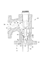
細まり形状絞り44はノズルスロート28の上流に配置される。絞り44は流れを真直にし、ノズルおよびディフューザ中心線の軸に直交する入口流れの影響の打ち消しを助ける。湾曲入口通路36と細まり形状絞り44との併用は、入口通路の形状に沿って流れが分離するのを防ぐとともに、ノズル38で厚い境界層を提供する。境界層が厚くなるとディフューザ境界層内に乱流が増加し、ディフューザ48のディフューザ壁46から流れが分離する性向を低くする。ディフューザ境界層での乱流は流れの本流中の運動量を壁から離してディフューザ境界層中へ移送するのを助け、かくして境界層の速度を高め、境界層が失速して分離する性向を低くする。
The narrowed
細まり形状絞り44の使用は、気体流量を継続的に増やしつつニードル30を更にノズルスロート28の外へ吸引できるようにするので、最大流量を増やすことができる。かかる形状を伴わない場合、ニードルがノズルスロートから引き抜かれるにつれて、それ以上流量が増加しない点が存在する。細まり形状絞り44は、面積勾配がほとんどゼロ(例えば、僅かに負)で始まり、ノズルスロート28へ近づくにつれて負の値が連続して大きくなるように成形される。この面積勾配は、流れ方向に沿う軸方向距離の単位長さ(例えばインチ(25.4mm))当たりの断面積の変化率である。
The use of the narrowed
ディフューザ48では広がり流れとなり、ここで流路断面積は流れ方向に沿って増加する。ノズル38の下流にあるディフューザ48の形状は、面積勾配が、ノズルスロート28近傍で小さな正の値で始まり、最大値に達してから、ディフューザ出口50でほぼゼロまで落ち込み、ここでの流路はほぼ円筒状である。ディフューザの端部は円筒状もしくはほぼ円筒状のチューブ52であってよい(すなわち、ほぼ一定断面積のチューブ)。一実施の形態では、このディフューザースリーブの断面積は、最初にノズルスロート28の下流直下で縮小するとともに、流れ方向に沿った方向で中高な湾曲であるようになされている。この中高湾曲形状は連続し、それにともない断面積はディフューザ内の流れ方向に沿った軸方向の位置で、出口フランジ42に向けて増加する。ディフューザ出口50の近傍では壁面の湾曲は中低となり、壁面がほぼ円筒形になるまでその面積勾配を減ずる。
In the
ディフューザ48がノズルスロート28の下流直下に小さな面積勾配を持つように成形することにより、ディフューザ壁46の最小内径をノズルスロートの下流へ来るようにする。この形状は、小さい弁開度で良好な臨界圧力比を維持しながら、ノズルスリーブから弁ニードル30が引き出される単位長さ当たりでの流量増加が略直線的である弁について、ストロークをより短くさせることができる。
By forming the
端部での面積勾配がほぼゼロ(ほぼ円筒形)であるディフューザ48の最大直径部位の軸方向長さは最大化されるが、これを弁の出口フランジを越えて、下流へ延びる隣接配管54内に突出させてもよい(図2を参照)。この延長部52はほぼ円筒形であり、外側フランジ位置でディフューザに接するようにもでき、あるいはディフューザ端のところで径方向に設けた外向き段差により僅かに大きい直径を持つようにしてもよい。延長部52の長さLは重要ではない。延長部52の機能は、気体流れの吐出方向をノズル38と一直線に維持するの助けることである。一実施の形態において、軸方向長さは、直径6インチ(152.4mm)の入口側および出口側配管用弁の場合は4インチ(101.6mm)である。延長部52のこの機能は、出口側配管54の始まりの部分の長さを、ディフューザの出口直径に等しいか、それよりも僅かに大きい縮小直径となるように設計することでもこと足りる。
The axial length of the largest diameter portion of the
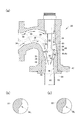
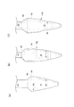
ニードル30は、長さ対直径比が1未満もしくは略1であってほぼ円筒形または僅かにテーパの付いた領域56を、弁20の流れ対ストローク特性をもたらすテーパが始まる軸方向位置の直上流に有する。この形状は流れがニードルの入口側に沿って分かれるのを防ぎ、ニードルに沿って厚い境界層を提供する。この厚い境界層が、ディフューザ境界層中の乱流を増やし、流れがノズルスロート28の下流のディフューザ48に突き出すニードル壁から分離する性向を縮小する。
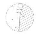
ニードル30はその外径部にある円錐形段差581(図4bを参照)または球形段差582(図4cを参照)を利用してノズル38のノズルスロート領域28に接触し、弁の全閉位置で気体流れを気密に遮断する。図6に円錐形段差58による遮断を示す。段差58がノズルスロート28の部分281にしっかりと接触していることが見て取れる。この段差58の半径方向高さを最小化して流れの分離を回避し、ほぼ円筒形または僅かにテーパの付いた領域56で発達する流れ境界層が消散されないように、そして段差58の下流にある栓部に沿って境界層の厚さを増すようにする。一実施の形態では、ほぼ円筒形または僅かにテーパの付いた領域56の、長さ対直径比が略1に等しい(図7bを参照)。
The
ほぼ円筒形の領域56の上流にある領域60でのニードルステム直径は縮小されている。ステム直径のこの縮小は、ニードルステム62の傍らを通って、入口側流れ配管とは反対側のノズルスロートを貫流する流れの渦度を最小化する。テーパ付移行部68をステム直径部と、ほぼ円筒形または僅かにテーパの付いた領域56との間に用いて、流れの分離を回避する。
The needle stem diameter in the
図7a乃至図7cは、本発明の弁20に使用できる弁ニードルのそれぞれ別の実施の形態を示す。図7aは、長さの短い(長さ対直径比が1未満)ほぼ円筒形またはテーパ付領域を示す。図7bおよび7cは二つの実施の形態を示し、そこでのほぼ円筒形または僅かにテーパの付いた領域56の長さ対直径比は略1である。
Figures 7a to 7c show different embodiments of valve needles that can be used with the
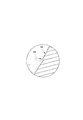
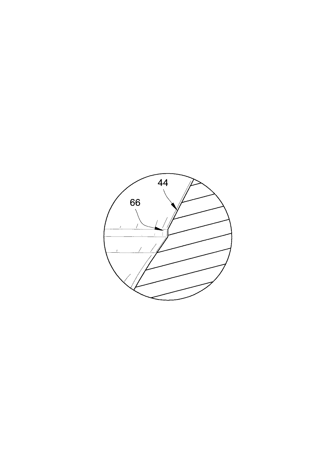
製造時には、機械加工(例えば旋盤加工)を行って、ノズルスロート28、細まり形状絞り44、およびディフューザ48の形状を加工している。弁の製造によっては、機械加工の合わさるところで表面の不連続となる、機械加工間での調整不良が認められることもある。一実施の形態では、ノズル/ディフューザ・スリーブ64を製作する機械加工において、機械加工ずれにより部品としての不連続部が置かれるが、両端から削除される材料の切削部分は、ノズルスロート28の可能な限り上流側に配置される。この許容差が外向段差66(図5を参照)であり、不連続部の下流の直径は不連続部での直径より大きくしてあるので、気体流れは滝のように流れてこの大きい方の直径部へ入る。
At the time of manufacture, machining (for example, lathe processing) is performed to process the shapes of the
弁内のフ流れを改良する技術を説明した。これら技術は、弁内での流れの性能を改善する。説明した技術を個別に利用しても、組み合わせて利用してもよい。例えば、縮小したニードルステムの直径、細まり形状絞り、ディフューザ延長部、および面積勾配パターンの技術を、単独でまたは組み合わせて、いかなるタイプの弁にも利用できる。 The technology to improve the flow in the valve was explained. These techniques improve flow performance within the valve. The described techniques may be used individually or in combination. For example, the reduced needle stem diameter, narrowed aperture, diffuser extension, and area gradient pattern techniques can be used for any type of valve, either alone or in combination.
本発明を説明する文脈での(特に、特許請求の範囲の文脈での)名詞及び同様な指示語の使用は、特に指示されない限り、または文脈によって明瞭に否定されない限り、単数および複数の両方を含むものと解釈すべきである。本明細書中で提供されたいずれの例示または例示的な用語(例えば、「等」)の使用も、単に本発明を説明し易くするという意図であるに過ぎず、特に請求の範囲に記載しない限り本発明の範囲に制限を加えるものではない。本明細書の語句は、本発明を実施する際の基本的な請求の範囲に含まれない要素を示すものと解釈すべきでない。 The use of nouns and similar directives in the context of describing the present invention (especially in the context of the claims) is intended to include both the singular and the plural unless specifically indicated otherwise or clearly denied by the context. It should be interpreted as including. The use of any examples or exemplary terms provided herein (eg, “etc.”) is merely intended to facilitate the description of the invention and is not specifically recited in the claims. As long as it does not limit the scope of the present invention. No language in the specification should be construed as indicating an element that is not included in the scope of the basic claims for carrying out the invention.
本発明の様々な実施の形態に関するこれまでの説明は、図解と説明の目的のために示されたものである。それは網羅することを意図したものではなく、また開示した精確な実施の形態に限定しようとするものではない。例えば、多くの形状および手法を亜音速弁にも使用できる。多くの変更や改変が上記の教示に照らして可能である。検討を行った実施の形態は、本発明の原理およびその実施での最善の説明を提供して、当該技術に通常に精通する者が本発明を、様々な実施の形態において並びに熟慮された特定の使途に合わせた様々な変更を伴って、利用できるようにする。かかる全ての変更および改変は、公正に、法的に、かつ公平に付与された権利の範囲に従って解釈したときに付帯の請求項で定められる本発明の範囲に含まれる。 The foregoing descriptions of various embodiments of the present invention have been presented for purposes of illustration and description. It is not intended to be exhaustive and is not intended to be limited to the precise embodiments disclosed. For example, many shapes and techniques can be used for subsonic valves. Many modifications and variations are possible in light of the above teaching. The discussed embodiments provide the principles of the invention and the best description of its practice, and those skilled in the art will recognize the invention in various embodiments as well as specific considerations. It can be used with various changes according to the purpose of use. All such changes and modifications are included within the scope of the present invention as defined in the appended claims when interpreted in accordance with the scope of rights granted fairly, legally and fairly.
本明細書と一体化されて、その一部を成す付帯図面は、本発明のいくつかの局面を示すとともに、以下の説明と共に本発明の原理を明らかにする。図面において、
20 ガス制御弁
22 アクチュエータ
24 気体入口
26 気体出口
28 ノズルスロート
30 弁ニードル
32 輪郭面
36 入口通路
38 ノズル
40 入口側配管
42 出口フランジ
44 細まり形状絞り
46 ディフューザ壁
48 ディフューザ
50 ディフューザ出口
52 円筒状もしくはほぼ円筒状のチューブ(延長部)
54 出口側配管
56 ほぼ円筒形または僅かにテーパの付いた領域
58 段差
60 ほぼ円筒形の領域の上流にある領域
62 ニードルステム
64 ノズル/ディフューザ・スリーブ
66 外向段差
68 テーパ付移行部
20
54
Claims (44)
前記入口通路に流体連通するノズル領域であって、ノズルスロートと、前記ノズルスロート上流に細まり形状絞りとを有する前記ノズル領域と;
前記ノズルスロートに流体連通する出口とを備える;
制御弁本体。 An inlet having an inlet passage;
A nozzle region in fluid communication with the inlet passage, the nozzle region having a nozzle throat and a narrowed aperture upstream of the nozzle throat;
An outlet in fluid communication with the nozzle throat;
Control valve body.
請求項1の弁本体。 The outlet has a diffuser, and the diffuser has an area gradient that increases from an initial starting position near the nozzle throat to a maximum value and decreases to zero at the outlet boundary,
The valve body according to claim 1.
請求項1の弁本体。 The inner diameter of the initial starting position is smaller than the inner diameter of the nozzle throat, and the initial starting position is downstream of the nozzle throat;
The valve body according to claim 1.
請求項2の弁本体。 The outlet has an outlet flange, and the diffuser extends beyond the outlet flange;
The valve body according to claim 2.
請求項1の弁本体。 The narrowed aperture is shaped such that its area gradient starts at approximately zero and the negative gradient increases as it approaches the nozzle throat.
The valve body according to claim 1.
請求項1の弁本体。 The inlet passage has a curved flow path;
The valve body according to claim 1.
請求項6の弁本体。 The cross-section of the inlet passage is measured in parallel to the flow direction from the side of the flow path having the larger radius of curvature measured in parallel to the flow direction. Is formed so that the side of the flow path having the smaller radius of curvature is smaller,
The valve body according to claim 6.
請求項6の弁本体。 The inlet passage has a substantially oval cross section,
The valve body according to claim 6.
前記入口通路の、前記入口に隣接する位置での断面積は、前記入口側配管の断面積未満である、
請求項1の弁本体。 The inlet is adapted to connect to an inlet-side pipe having a cross-sectional area, and a cross-sectional area of the inlet passage at a position adjacent to the inlet is less than a cross-sectional area of the inlet-side pipe;
The valve body according to claim 1.
請求項9の弁本体。 The inlet passage is adjacent to the inlet side pipe so that the flow path at a position adjacent to the inlet is as far as possible from the outlet flange of the outlet so that the flow path is eccentric with respect to the inlet side pipe. Begins,
The valve body according to claim 9.
請求項1の弁本体。 In addition, the valve needle is adapted to be movable between a shut-off position and a closed position, the valve needle having a generally cylindrical region upstream of the axial position that begins to taper to provide a flow-to-stroke characteristic of the valve body. Have;
The valve body according to claim 1.
請求項11の弁本体。 The generally cylindrical region has a length to diameter ratio of less than 1 and approximately 1;
The valve body of claim 11.
請求項11の弁本体。 The valve needle has one of a conical step and a spherical step on the outer shape of the valve needle, and the one of the conical step and the spherical step contacts the nozzle throat to fully close the valve. Is adapted to provide a gas flow shut-off at the location,
The valve body of claim 11.
前記弁ステムの直径は、前記ほぼ円筒形領域の上流の位置での前記ほぼ円筒形領域の直径より小さい、
請求項11の弁本体。 The valve needle has a valve stem;
The diameter of the valve stem is smaller than the diameter of the substantially cylindrical region at a position upstream of the substantially cylindrical region;
The valve body of claim 11.
請求項14の弁本体。 And a tapered transition between the small diameter valve stem and the substantially cylindrical region,
The valve body of claim 14.
請求項1の弁本体。 Further, an outward step for allowing inconsistency between machining is provided in the narrowed-shaped aperture.
The valve body according to claim 1.
前記入口通路に流体連通するノズル領域であって、ノズルスロートを有するノズル領域と;
前記ノズルスロートに流体連通する出口と;
前記ノズルスロートに接触している閉位置と、前記ノズルスロートから離間している開位置との間を移動できるようになされた弁ニードルであって、弁ニードルは、テーパが始まって弁本体の流れ対ストローク特性をもたらす軸位置の上流にほぼ円筒形領域を有する弁ニードルとを備える;
弁。 An inlet having an inlet passage;
A nozzle region in fluid communication with the inlet passage, the nozzle region having a nozzle throat;
An outlet in fluid communication with the nozzle throat;
A valve needle adapted to move between a closed position in contact with the nozzle throat and an open position spaced from the nozzle throat, wherein the valve needle begins to taper and the flow of the valve body A valve needle having a substantially cylindrical region upstream of the axial position providing anti-stroke characteristics;
valve.
請求項17の弁。 The generally cylindrical region has a length-to-diameter ratio of less than 1 and approximately 1.
The valve of claim 17.
請求項17の弁。 The fuel inlet is orthogonal to the fuel outlet;
The valve of claim 17.
請求項19の弁。 The inlet passage is curved, thus forcing the inlet flow towards the nozzle in a more uniform manner;
The valve of claim 19.
請求項20の弁。 The curved channel and the narrowed-shaped restriction are adapted to prevent flow from separating along the inlet passage and to provide a relatively thick boundary layer at the nozzle.
21. The valve of claim 20.
請求項17の弁。 And further comprising a narrowed-shaped stop upstream of the nozzle throat, wherein the narrowed-shaped stop is shaped such that its area gradient starts slightly negative and increases toward the nozzle throat.
The valve of claim 17.
請求項22の弁。 The area gradient is shaped in such a way that the area gradient first curves inwardly and then curves outwardly.
23. The valve of claim 22.
請求項17の弁本体。 The valve needle has one of a conical step and a spherical step on the outer shape of the valve needle, and the one of the conical step and the spherical step is when the previous valve needle is in a fully closed position. Made to contact the nozzle throat so as to provide a hermetic shut-off,
The valve body of claim 17.
請求項17の弁本体。 The valve needle has a valve stem, and the diameter of the valve stem is the diameter of the substantially cylindrical region so as to minimize the vorticity of the flow through the valve stem and opposite the inlet passage. Smaller,
The valve body of claim 17.
請求項25の弁本体。 And a tapered transition between the small diameter valve stem and the substantially cylindrical region.
The valve body of claim 25.
前記入口通路に流体連通し、ノズルスロートを有するノズル領域と;
前記ノズルスロートに流体連通する出口と;
前記ノズルスロートに接触している閉位置と、前記ノズルスロートから離間している開位置との間を移動できるようになされた弁ニードルとを備える;
弁。 An inlet configured to connect to an inlet side pipe, the inlet having a curved inlet passage having a smaller cross-sectional area than a cross-sectional area of the inlet side pipe;
A nozzle region in fluid communication with the inlet passage and having a nozzle throat;
An outlet in fluid communication with the nozzle throat;
A valve needle adapted to be movable between a closed position contacting the nozzle throat and an open position spaced from the nozzle throat;
valve.
請求項27の弁。 The cross-sectional area of the curved inlet passage is adjacent to the inlet-side piping so that the gas passage is eccentric with respect to the inlet-side piping so that the inlet passage is as far as possible from the outlet flange of the fuel outlet. Starting with
28. The valve of claim 27.
請求項27の弁。 The cross-sectional area of the curved inlet passage is such that the radius of curvature measured perpendicular to the flow direction is parallel to the flow direction from the side of the flow path having the larger radius of curvature measured parallel to the flow direction. Molded so that the side of the channel with the smaller radius of curvature to be measured is smaller,
28. The valve of claim 27.
請求項27の弁。 A cross-sectional area of the curved inlet passage is substantially elliptical;
28. The valve of claim 27.
請求項27の弁。 The outlet has a diffuser, and the diffuser is shaped so that its area gradient increases from an initial starting position near the nozzle throat to a maximum and drops to approximately zero at the fuel outlet boundary.
28. The valve of claim 27.
請求項31の弁。 The inner diameter of the initial starting position is smaller than the inner diameter of the nozzle throat, and the initial starting position is downstream of the nozzle throat;
32. The valve of claim 31.
請求項27の弁。 Further, a narrowed diaphragm is provided between the nozzle throat and the curved inlet passage.
28. The valve of claim 27.
請求項33の弁。 The narrowed aperture is shaped such that its area gradient starts from approximately zero and the negative gradient increases as the narrowed aperture approaches the nozzle throat.
34. The valve of claim 33.
前記入口通路に流体連通し、ノズルスロートと、前記ノズルスロート上流の細まり形状絞りとを有するノズル領域と;
前記ノズルスロートに流体連通する出口であって、前記出口はディフューザを有し、前記ディフューザは、その面積勾配が、前記ノズルスロート近傍の初めの開始位置から最大値まで増加し、前記出口の境界でゼロまで下がるように整形されるようになした前記出口と;
前記ノズルスロートに接触している閉位置と、前記ノズルスロートから離間している開位置との間を移動できるようになされた弁ニードルであって、テーパが始まって弁本体の流れ対ストローク特性をもたらす軸位置の上流にほぼ円筒形領域を有する弁ニードルとを備える;
弁。 An inlet adapted to connect to the inlet side piping and having a curved inlet passage;
A nozzle region in fluid communication with the inlet passage and having a nozzle throat and a narrowed throttle upstream of the nozzle throat;
An outlet in fluid communication with the nozzle throat, the outlet having a diffuser, the diffuser having an area gradient that increases from an initial starting position in the vicinity of the nozzle throat to a maximum value at the boundary of the outlet; Said exit adapted to be shaped to drop to zero;
A valve needle adapted to move between a closed position in contact with the nozzle throat and an open position spaced from the nozzle throat. A valve needle having a substantially cylindrical region upstream of the resulting axial position;
valve.
請求項35の弁。 The generally cylindrical region has a length-to-diameter ratio of approximately 1 and less than 1;
36. The valve of claim 35.
請求項35の弁。 The narrowed aperture is shaped so that its area gradient starts at approximately zero and the negative gradient increases as it approaches the nozzle throat,
36. The valve of claim 35.
請求項35の弁。 The inner diameter of the initial starting position is smaller than the inner diameter of the nozzle throat, and the initial starting position is downstream of the nozzle throat;
36. The valve of claim 35.
請求項35の弁。 The cross-sectional area of the curved inlet passage is adjacent to the inlet side piping so that the gas passage is eccentric with respect to the inlet side piping so that the inlet passage is as far as possible from the outlet flange of the outlet. Begins,
36. The valve of claim 35.
請求項35の弁。 The cross-sectional area of the curved inlet passage is such that the radius of curvature measured perpendicular to the flow direction is parallel to the flow direction from the side of the flow path having the larger radius of curvature measured parallel to the flow direction. Molded so that the side of the channel with the smaller radius of curvature to be measured is smaller,
36. The valve of claim 35.
前記入口通路は、前記入口側配管の断面積より小さな断面積を前記入口近傍の位置に有する、
請求項35の弁。 The inlet is adapted to connect to an inlet-side pipe having a cross-sectional area, and the inlet passage has a cross-sectional area smaller than that of the inlet-side pipe at a position near the inlet;
36. The valve of claim 35.
請求項35の弁。 The diffuser extends beyond the outlet flange of the outlet;
36. The valve of claim 35.
請求項35の弁。 The initial length portion of the outlet side pipe connected to the diffuser has an inner diameter that is smaller than the inner diameter of the outlet side pipe, thus extending the diffuser.
36. The valve of claim 35.
請求項35の弁。 In addition, an outward step is provided in the narrowed diaphragm to allow for discrepancies between machining.
36. The valve of claim 35.
Applications Claiming Priority (2)
| Application Number | Priority Date | Filing Date | Title |
|---|---|---|---|
| US10/796,811 | 2004-03-09 | ||
| US10/796,811 US7044434B2 (en) | 2004-03-09 | 2004-03-09 | High recovery sonic gas valve |
Publications (2)
| Publication Number | Publication Date |
|---|---|
| JP2005291201A true JP2005291201A (en) | 2005-10-20 |
| JP4979197B2 JP4979197B2 (en) | 2012-07-18 |
Family
ID=34827620
Family Applications (1)
| Application Number | Title | Priority Date | Filing Date |
|---|---|---|---|
| JP2005062534A Expired - Fee Related JP4979197B2 (en) | 2004-03-09 | 2005-03-07 | High recovery sonic gas valve |
Country Status (4)
| Country | Link |
|---|---|
| US (1) | US7044434B2 (en) |
| EP (1) | EP1574764B1 (en) |
| JP (1) | JP4979197B2 (en) |
| AT (1) | ATE510156T1 (en) |
Cited By (2)
| Publication number | Priority date | Publication date | Assignee | Title |
|---|---|---|---|---|
| JP2012163212A (en) * | 2005-11-23 | 2012-08-30 | Fisher Controls Internatl Llc | Vorticity generator for use with fluid control system |
| JP2021046830A (en) * | 2019-09-19 | 2021-03-25 | 愛三工業株式会社 | Egr valve and egr valve device having the same |
Families Citing this family (33)
| Publication number | Priority date | Publication date | Assignee | Title |
|---|---|---|---|---|
| US6769666B2 (en) * | 2001-11-15 | 2004-08-03 | Fisher Controls International Llc | Variable port valve plug |
| US7467778B2 (en) * | 2003-09-15 | 2008-12-23 | Exxonmobil Upstream Research Company | Slurry tolerant pilot operated relief valve |
| CN101076439B (en) | 2004-12-28 | 2011-08-24 | 倍耐力轮胎股份公司 | Method and apparatus for manufacturing wheel tires |
| JP2007024241A (en) * | 2005-07-20 | 2007-02-01 | Denso Corp | Fluid control valve |
| US8689883B2 (en) * | 2006-02-22 | 2014-04-08 | Weatherford/Lamb, Inc. | Adjustable venturi valve |
| WO2007095951A1 (en) * | 2006-02-23 | 2007-08-30 | Scanima A/S | Powder valve |
| US20080057848A1 (en) * | 2006-08-31 | 2008-03-06 | Honeywell International, Inc. | Venturi gate valve assembly for an auxiliary power unit |
| US20080149182A1 (en) * | 2006-12-21 | 2008-06-26 | M-I Llc | Linear motor to control hydraulic force |
| US8418989B2 (en) * | 2006-12-21 | 2013-04-16 | M-I L.L.C. | Pressure-balanced choke system |
| US8006715B2 (en) * | 2007-09-20 | 2011-08-30 | Caterpillar Inc. | Valve with thin-film coating |
| ATE557222T1 (en) * | 2008-05-20 | 2012-05-15 | Parker Hannifin Corp | DOSING SOLENOID VALVE |
| US8038121B2 (en) | 2009-01-06 | 2011-10-18 | Woodward, Inc. | Fluid control valve with sensing port |
| EP2588213A4 (en) * | 2010-07-02 | 2016-01-06 | Enfield Technologies Llc | Corrective measures and devices for bi-stable flow phenomena in fluid valves |
| TWI481844B (en) * | 2012-03-02 | 2015-04-21 | China Steel Corp | Positive and negative micro pressure relief valve detection device |
| DE102013107389B4 (en) * | 2013-07-12 | 2023-06-01 | Svm Schultz Verwaltungs-Gmbh & Co. Kg | pressure control valve |
| US9279502B2 (en) | 2014-01-30 | 2016-03-08 | Fives Bronx, Inc. | Fill valve apparatus |
| NO336259B1 (en) * | 2014-02-03 | 2015-07-06 | Subsea Chokes Internat As | Valve for flow control of a fluid |
| US10295064B2 (en) * | 2014-03-19 | 2019-05-21 | Zhejiang Sanhua Co., Ltd | Electronic expansion valve |
| DE102014015555B3 (en) * | 2014-10-22 | 2015-11-19 | Bundesrepublik Deutschland, vertr. durch das Bundesministerium für Wirtschaft und Energie, dieses vertreten durch den Präsidenten der Physikalisch-Technischen Bundesanstalt | Method for detecting the criticality of a differential pressure device and device for embodying a flow |
| US9915353B2 (en) | 2014-10-28 | 2018-03-13 | Fisher Controls International Llc | Choked flow valve with clamped seat ring |
| US10392786B2 (en) | 2015-01-19 | 2019-08-27 | Moen Incorporated | Electronic plumbing fixture fitting with electronic valve including piston and seat |
| US20170082035A1 (en) * | 2015-09-21 | 2017-03-23 | Moog Inc. | Gas turbine active combustion instability control system |
| US10544879B2 (en) * | 2016-01-25 | 2020-01-28 | Moog Inc. | Sonic flow control valve |
| JP6461872B2 (en) * | 2016-08-30 | 2019-01-30 | 株式会社不二工機 | Motorized valve |
| US10551856B2 (en) | 2017-02-23 | 2020-02-04 | Fisher Controls International Llc | Fluid control valve having discrete flow channels arranged to equalize the velocity of fluid at the perimeter of the valve port |
| US10960237B2 (en) | 2017-07-19 | 2021-03-30 | Honeywell International Inc. | Powered air-purifying respirator (PAPR) with eccentric venturi air flow rate determination |
| CN109185479A (en) * | 2018-09-14 | 2019-01-11 | 珠海格力电器股份有限公司 | Valve and device with valve |
| US11624442B2 (en) * | 2021-02-15 | 2023-04-11 | Fisher Controls International Llc | Push-down-to-open high recovery choke valves |
| US11512795B2 (en) * | 2021-03-26 | 2022-11-29 | Honeywell International Inc. | Noise abatement in a venturi valve |
| CN113638823B (en) * | 2021-08-10 | 2022-06-17 | 北京理工大学 | Needle valve type flow-adjustable gas generator ground test device |
| US11713813B2 (en) | 2022-01-03 | 2023-08-01 | Woodward, Inc. | Inline variable sonic valve |
| CN114788978B (en) * | 2022-05-07 | 2024-04-12 | 长沙有色冶金设计研究院有限公司 | Novel pressure leaching process tail gas treatment device and method |
| BE1032909B1 (en) * | 2024-08-29 | 2026-04-15 | Safran Aero Boosters Sa | Turbomachine equipped with a sonic control valve for gaseous fluids |
Citations (3)
| Publication number | Priority date | Publication date | Assignee | Title |
|---|---|---|---|---|
| US4413646A (en) * | 1981-05-01 | 1983-11-08 | Exxon Research And Engineering Co. | Streamline coal slurry letdown valve |
| JPS6260770U (en) * | 1985-10-04 | 1987-04-15 | ||
| US4707278A (en) * | 1984-12-03 | 1987-11-17 | Herion-Werke Kg | Control valve |
Family Cites Families (4)
| Publication number | Priority date | Publication date | Assignee | Title |
|---|---|---|---|---|
| US3889537A (en) * | 1973-10-11 | 1975-06-17 | Gen Electric | Venturi arrangement |
| US4721284A (en) * | 1986-11-06 | 1988-01-26 | Norriseal Controls | Valve plug design |
| GB2351140B (en) * | 1999-06-15 | 2001-05-09 | Masterflo Valve Inc | Choke valve for throttling fluid flow |
| BR0211292A (en) * | 2001-08-17 | 2004-08-03 | Fisher Controls Int | Fluid control valve and seating ring for use in a fluid control valve |
-
2004
- 2004-03-09 US US10/796,811 patent/US7044434B2/en not_active Expired - Lifetime
-
2005
- 2005-03-03 AT AT05004730T patent/ATE510156T1/en not_active IP Right Cessation
- 2005-03-03 EP EP05004730A patent/EP1574764B1/en not_active Expired - Lifetime
- 2005-03-07 JP JP2005062534A patent/JP4979197B2/en not_active Expired - Fee Related
Patent Citations (3)
| Publication number | Priority date | Publication date | Assignee | Title |
|---|---|---|---|---|
| US4413646A (en) * | 1981-05-01 | 1983-11-08 | Exxon Research And Engineering Co. | Streamline coal slurry letdown valve |
| US4707278A (en) * | 1984-12-03 | 1987-11-17 | Herion-Werke Kg | Control valve |
| JPS6260770U (en) * | 1985-10-04 | 1987-04-15 |
Cited By (3)
| Publication number | Priority date | Publication date | Assignee | Title |
|---|---|---|---|---|
| JP2012163212A (en) * | 2005-11-23 | 2012-08-30 | Fisher Controls Internatl Llc | Vorticity generator for use with fluid control system |
| JP2021046830A (en) * | 2019-09-19 | 2021-03-25 | 愛三工業株式会社 | Egr valve and egr valve device having the same |
| US11913412B2 (en) | 2019-09-19 | 2024-02-27 | Aisan Kogyo Kabushiki Kaisha | EGR valve and EGR valve device provided with same |
Also Published As
| Publication number | Publication date |
|---|---|
| US20050199840A1 (en) | 2005-09-15 |
| EP1574764A3 (en) | 2005-10-05 |
| ATE510156T1 (en) | 2011-06-15 |
| EP1574764A8 (en) | 2005-12-21 |
| US7044434B2 (en) | 2006-05-16 |
| EP1574764B1 (en) | 2011-05-18 |
| JP4979197B2 (en) | 2012-07-18 |
| EP1574764A2 (en) | 2005-09-14 |
Similar Documents
| Publication | Publication Date | Title |
|---|---|---|
| JP4979197B2 (en) | High recovery sonic gas valve | |
| US20240003465A1 (en) | Fluid flow control devices and systems, and methods of flowing fluids therethrough | |
| KR101643517B1 (en) | Steam valve | |
| US20040051072A1 (en) | High-stability valve arrangement for a governor valve | |
| EP3341615B1 (en) | Restrictors using the venturi effect | |
| US5413145A (en) | Low-pressure-drop critical flow venturi | |
| CN114384271A (en) | Flow regulator and throughflow measurement system | |
| JP5976065B2 (en) | Fuel injection valve | |
| US3647176A (en) | Cavitating throttling valve | |
| CN102908919A (en) | Fluid mixer | |
| CN218326281U (en) | Valve trim assembly | |
| JPS5865904A (en) | Control valve of steam turbine | |
| CN221401727U (en) | A valve device | |
| JP2005140672A (en) | Intake duct device | |
| CN219345595U (en) | Unidirectional component | |
| US20250283540A1 (en) | Bi-stable valve | |
| CN117267455A (en) | Noise reduction device, electronic expansion valve and noise reduction method | |
| JP2002188944A (en) | Flow measuring device having restrictor | |
| CN111946832A (en) | Water valve and gas equipment with same | |
| CN117546029A (en) | Flow velocity meter |
Legal Events
| Date | Code | Title | Description |
|---|---|---|---|
| A521 | Request for written amendment filed |
Free format text: JAPANESE INTERMEDIATE CODE: A523 Effective date: 20060710 |
|
| A521 | Request for written amendment filed |
Free format text: JAPANESE INTERMEDIATE CODE: A821 Effective date: 20060710 |
|
| A621 | Written request for application examination |
Free format text: JAPANESE INTERMEDIATE CODE: A621 Effective date: 20080214 |
|
| A131 | Notification of reasons for refusal |
Free format text: JAPANESE INTERMEDIATE CODE: A131 Effective date: 20100615 |
|
| A601 | Written request for extension of time |
Free format text: JAPANESE INTERMEDIATE CODE: A601 Effective date: 20100915 |
|
| A602 | Written permission of extension of time |
Free format text: JAPANESE INTERMEDIATE CODE: A602 Effective date: 20100921 |
|
| A601 | Written request for extension of time |
Free format text: JAPANESE INTERMEDIATE CODE: A601 Effective date: 20101015 |
|
| A602 | Written permission of extension of time |
Free format text: JAPANESE INTERMEDIATE CODE: A602 Effective date: 20101020 |
|
| A521 | Request for written amendment filed |
Free format text: JAPANESE INTERMEDIATE CODE: A523 Effective date: 20101115 |
|
| A131 | Notification of reasons for refusal |
Free format text: JAPANESE INTERMEDIATE CODE: A131 Effective date: 20110705 |
|
| A521 | Request for written amendment filed |
Free format text: JAPANESE INTERMEDIATE CODE: A523 Effective date: 20111005 |
|
| RD03 | Notification of appointment of power of attorney |
Free format text: JAPANESE INTERMEDIATE CODE: A7423 Effective date: 20111226 |
|
| A521 | Request for written amendment filed |
Free format text: JAPANESE INTERMEDIATE CODE: A821 Effective date: 20111227 |
|
| TRDD | Decision of grant or rejection written | ||
| A01 | Written decision to grant a patent or to grant a registration (utility model) |
Free format text: JAPANESE INTERMEDIATE CODE: A01 Effective date: 20120410 |
|
| A01 | Written decision to grant a patent or to grant a registration (utility model) |
Free format text: JAPANESE INTERMEDIATE CODE: A01 |
|
| A61 | First payment of annual fees (during grant procedure) |
Free format text: JAPANESE INTERMEDIATE CODE: A61 Effective date: 20120417 |
|
| FPAY | Renewal fee payment (event date is renewal date of database) |
Free format text: PAYMENT UNTIL: 20150427 Year of fee payment: 3 |
|
| R150 | Certificate of patent or registration of utility model |
Ref document number: 4979197 Country of ref document: JP Free format text: JAPANESE INTERMEDIATE CODE: R150 Free format text: JAPANESE INTERMEDIATE CODE: R150 |
|
| R250 | Receipt of annual fees |
Free format text: JAPANESE INTERMEDIATE CODE: R250 |
|
| R250 | Receipt of annual fees |
Free format text: JAPANESE INTERMEDIATE CODE: R250 |
|
| R250 | Receipt of annual fees |
Free format text: JAPANESE INTERMEDIATE CODE: R250 |
|
| R250 | Receipt of annual fees |
Free format text: JAPANESE INTERMEDIATE CODE: R250 |
|
| R250 | Receipt of annual fees |
Free format text: JAPANESE INTERMEDIATE CODE: R250 |
|
| R250 | Receipt of annual fees |
Free format text: JAPANESE INTERMEDIATE CODE: R250 |
|
| R250 | Receipt of annual fees |
Free format text: JAPANESE INTERMEDIATE CODE: R250 |
|
| R250 | Receipt of annual fees |
Free format text: JAPANESE INTERMEDIATE CODE: R250 |
|
| LAPS | Cancellation because of no payment of annual fees |