JP2005291168A - Antistatic plate - Google Patents
Antistatic plate Download PDFInfo
- Publication number
- JP2005291168A JP2005291168A JP2004110691A JP2004110691A JP2005291168A JP 2005291168 A JP2005291168 A JP 2005291168A JP 2004110691 A JP2004110691 A JP 2004110691A JP 2004110691 A JP2004110691 A JP 2004110691A JP 2005291168 A JP2005291168 A JP 2005291168A
- Authority
- JP
- Japan
- Prior art keywords
- ignition coil
- negative electrode
- antistatic plate
- plate
- antistatic
- Prior art date
- Legal status (The legal status is an assumption and is not a legal conclusion. Google has not performed a legal analysis and makes no representation as to the accuracy of the status listed.)
- Pending
Links
- 230000017525 heat dissipation Effects 0.000 claims 1
- 230000003068 static effect Effects 0.000 abstract description 8
- 230000005611 electricity Effects 0.000 abstract description 7
- 230000005855 radiation Effects 0.000 description 9
- 239000000463 material Substances 0.000 description 5
- 238000002485 combustion reaction Methods 0.000 description 3
- 229910001369 Brass Inorganic materials 0.000 description 2
- RYGMFSIKBFXOCR-UHFFFAOYSA-N Copper Chemical compound [Cu] RYGMFSIKBFXOCR-UHFFFAOYSA-N 0.000 description 2
- 229910052782 aluminium Inorganic materials 0.000 description 2
- XAGFODPZIPBFFR-UHFFFAOYSA-N aluminium Chemical compound [Al] XAGFODPZIPBFFR-UHFFFAOYSA-N 0.000 description 2
- 239000010951 brass Substances 0.000 description 2
- 238000001816 cooling Methods 0.000 description 2
- 229910052802 copper Inorganic materials 0.000 description 2
- 239000010949 copper Substances 0.000 description 2
- 238000010586 diagram Methods 0.000 description 2
- 229910052751 metal Inorganic materials 0.000 description 2
- 239000002184 metal Substances 0.000 description 2
- CWYNVVGOOAEACU-UHFFFAOYSA-N Fe2+ Chemical compound [Fe+2] CWYNVVGOOAEACU-UHFFFAOYSA-N 0.000 description 1
- 239000000446 fuel Substances 0.000 description 1
- 238000009434 installation Methods 0.000 description 1
- 239000000696 magnetic material Substances 0.000 description 1
- 230000002093 peripheral effect Effects 0.000 description 1
Images
Landscapes
- Ignition Installations For Internal Combustion Engines (AREA)
Abstract
Description
本発明は、エンジンの各気筒毎に取り付けられた点火プラグに装着されるイグニッションコイルの帯電を防止するために設置される帯電防止板に関する。 The present invention relates to an antistatic plate installed to prevent charging of an ignition coil attached to a spark plug attached to each cylinder of an engine.
自動車等の車両の内燃機関において、複数気筒のシリンダ内の燃料を順次効率よく燃焼させるものとして、各気筒毎に取り付けられた点火プラグに高圧電流を発生させためにイグニッションコイルがある。バッテリからの一次電流をイグニッションコイルにて高圧の2次電流に変換して、これを各気筒の点火時期に適合させてディストリビュータ(配電装置)により分配していた。しかしながら、近年では、ダイレクトイグニッション点火方式が主流になってきている。つまり、コンピュータ制御により分配されたバッテリーからの1次電流を、気筒毎に備えたイグニッションコイルによって、高圧の2次電流を得てこれを点火プラグに供給するというものである。 2. Description of the Related Art In an internal combustion engine of a vehicle such as an automobile, an ignition coil is used to generate a high-voltage current in a spark plug attached to each cylinder as one that sequentially burns fuel in a cylinder of a plurality of cylinders. The primary current from the battery is converted into a high-voltage secondary current by an ignition coil, and this is adapted to the ignition timing of each cylinder and distributed by a distributor (distribution device). However, in recent years, the direct ignition ignition system has become mainstream. That is, the primary current from the battery distributed by computer control is obtained by the ignition coil provided for each cylinder, and a high-voltage secondary current is obtained and supplied to the spark plug.
このような各気筒毎に配設される点火プラグやイグニッションコイルの周辺には、正極線によって高圧のプラス電流が流れて点火プラグを発火させた後で、負の静電気が帯電することは避けられない。また、イグニッションコイルを燃焼室の近傍に配置したが故に、この近傍にて高温が蓄積し易い構造となった。点火プラグやイグニッションコイルはそれらの負極側がエンジンヘッドへのねじ込みや取付板を介したエンジンヘッドへの取付け等により、直接に車体を介してアースを得ているものの、依然として静電気の帯電が残留し、不安定な点火やエンジンの出力の低下を招く虞れがあった。そこで、点火プラグの帯電を有効に防止する提案がなされた(例えば下記特許文献1参照)。
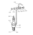
前記特許文献1に開示された発明は、図7に示すように、点火プラグの接地電極と一体化された主体金具(ロ)のボルト頭部(ハ)とシリンダーヘッドへの装着外周ブラケット(ニ)との中間部に高電圧印加用端子方向へ突出した棒状の端子(ヘ)を溶接し、この棒状の端子は末端部に導線(リ)を接続し、点火装置のマイナス側回路から車台アースされている導線と一緒にバッテリーマイナス端子に接続し、点火装置から接地電極へ直接通電回路を確保するものである。
As shown in FIG. 7, the invention disclosed in
しかしながら、前記特許文献1に開示されたものは、エンジンヘッドにねじ込めれた点火プラグのねじ部から直接にアースを得る他、各点火プラグ毎に、その負極に接続された板状体およびアース線によって、車体とは別途に直接にバッテリの負極に接続しただけのものであるため、気筒の数だけアース線を要して煩雑になる上に、配線作業に手間取り、配線材料費のコストアップを招いていた。また、高温対策は何ら講じられていない。
However, the one disclosed in
そこで、本発明では、前記従来の点火プラグ等における帯電防止装置における諸課題を解決して、構造が簡素で、取付作業も簡便に行え、イグニッションコイルの帯電を有効に防止できるとともに、高温対策にも有効な帯電防止板を提供することを目的とする。 Therefore, in the present invention, the problems in the conventional antistatic device such as the spark plug are solved, the structure is simple, the mounting work can be easily performed, the ignition coil can be effectively prevented from being charged, and the countermeasure against high temperature is taken. Another object of the present invention is to provide an effective antistatic plate.
そのため本発明は、エンジンの各気筒毎に取り付けられた点火プラグに装着されるイグニッションコイルの帯電を防止するために設置される帯電防止板において、エンジンヘッドに取付ボルトを介して取り付けられる各イグニッションコイル負極板への取付部が形成されるとともに、バッテリー負極あるいはバッテリー負極と導通する車体およびエンジン部と連結されるアース線取付部が設けられたことを特徴とする。また本発明は、前記帯電防止板に放熱孔が穿設されたことを特徴とする。また本発明は、前記放熱孔あるいはイグニッションコイル収容切欠きの周囲に放熱フィンが起立形成されたことを特徴とするもので、これらを課題解決のための手段とするものである。 Therefore, the present invention provides an antistatic plate installed to prevent charging of an ignition coil attached to a spark plug attached to each cylinder of the engine, and each ignition coil attached to the engine head via a mounting bolt. An attachment portion to the negative electrode plate is formed, and a battery negative electrode or a ground wire attachment portion connected to the vehicle body and the engine portion connected to the battery negative electrode is provided. Further, the present invention is characterized in that a heat radiating hole is formed in the antistatic plate. Further, the present invention is characterized in that a heat radiating fin is formed upright around the heat radiating hole or the ignition coil accommodating notch, and these are used as means for solving the problem.
本発明では、エンジンの各気筒毎に取り付けられた点火プラグに装着されるイグニッションコイルの帯電を防止するために設置される帯電防止板において、エンジンヘッドに取付ボルトを介して取り付けられる各イグニッションコイル負極板への取付部が形成されるとともに、バッテリー負極あるいはバッテリー負極と導通する車体およびエンジン部と連結されるアース線取付部が設けられたことにより、気筒毎に取り付けられたイグニッションコイルの負極に発生した静電気を、取りまとめて帯電防止板に集電して、導電性のよいアース線にて直接にバッテリの負極に伝達することを可能にする。しかも、帯電防止板の取付けに関しては、エンジンヘッドへの取付板であるイグニッションコイル負極板に共締めすることで、取付けと負極からの静電気の取り出しが同時に行え、構造が簡素化され、取付け作業も簡便になる。 In the present invention, each ignition coil negative electrode attached to the engine head via a mounting bolt in an antistatic plate installed to prevent charging of an ignition coil attached to a spark plug attached to each cylinder of the engine Generated at the negative electrode of the ignition coil attached to each cylinder by forming the mounting part to the plate and providing the battery negative electrode or the vehicle body conducting with the battery negative electrode and the ground wire attaching part connected to the engine part The collected static electricity is collected and collected on the antistatic plate, and can be directly transmitted to the negative electrode of the battery through a conductive ground wire. In addition, regarding the attachment of the antistatic plate, it can be attached to the negative electrode plate of the ignition coil, which is the attachment plate to the engine head, so that the attachment and the removal of static electricity from the negative electrode can be performed simultaneously, the structure is simplified, and the installation work is also simplified. It becomes simple.
また、前記帯電防止板に放熱孔が穿設された場合は、イグニッションコイルに高圧電流の発生に伴って生じる高熱が、放熱孔を貫通する走行風等によって有効に空中に放散される。しかも、これらの放熱孔によって、材料費の節減を可能にして軽量化される。さらに、前記放熱孔あるいはイグニッションコイル収容切欠きの周囲に放熱フィンが起立形成された場合は、放熱面積が増大して、さらに迅速に冷却機能が発揮される。 Further, when the heat dissipating hole is formed in the antistatic plate, the high heat generated by the generation of the high voltage current in the ignition coil is effectively dissipated into the air by the traveling wind passing through the heat dissipating hole. Moreover, these heat radiating holes can reduce the material cost by reducing the material cost. Further, when the heat radiation fins are formed upright around the heat radiation hole or the ignition coil housing notch, the heat radiation area is increased and the cooling function is exhibited more quickly.
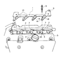
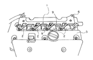
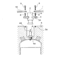
以下、本発明の実施例を図面に基づいて詳細に説明する。図1〜図3は本発明の帯電防止板の第1実施例を示すもので、図1は帯電防止板を取り付ける前のエンジンヘッドの全体斜視図、図2は帯電防止板を取り付けた後のエンジンの全体斜視図、図3は1つの気筒の点火プラグおよびイグニッションコイルの取付け状態を示す要部断面図である。本発明の基本的な構成は、図1に示すように、エンジンの各気筒毎に取り付けられた点火プラグに装着されるイグニッションコイル2、2・・の帯電を防止するために設置される帯電防止板1において、エンジンヘッド5に取付ボルト(8)を介して取り付けられる各イグニッションコイル負極板3への取付部1Bが形成されるとともに、バッテリー負極あるいはバッテリー負極と導通する車体およびエンジ部と連結されるアース線取付部6が設けられたことを特徴とする。
Hereinafter, embodiments of the present invention will be described in detail with reference to the drawings. 1 to 3 show a first embodiment of an antistatic plate according to the present invention. FIG. 1 is an overall perspective view of an engine head before attaching the antistatic plate, and FIG. 2 shows a state after attaching the antistatic plate. FIG. 3 is a cross-sectional view of the main part showing an attachment state of an ignition plug and an ignition coil of one cylinder. As shown in FIG. 1, the basic configuration of the present invention is an antistatic device installed to prevent the
以下に詳述する。図1〜図3に示す本発明の帯電防止板の第1実施例は、4気筒のエンジンに取り付けられる帯電防止板の例である。図1に示すように、4つのイグニッションコイル2はそれぞれの取付板である負極板3によって、エンジンヘッド5の対応する部位に取り付けられている。本発明の帯電防止板1は、前記イグニッションコイル2をエンジンヘッド5に取り付けている前記負極板3の取付ボルト8(図3)を取り外し、この取付孔3Aを利用して帯電防止板1の取付部1Bを取り付けるものである。
This will be described in detail below. The first embodiment of the antistatic plate of the present invention shown in FIGS. 1 to 3 is an example of an antistatic plate attached to a 4-cylinder engine. As shown in FIG. 1, the four
好適には、帯電防止板1は導電性の良いアルミニウム、真鍮、銅等の非鉄金属の非磁性体により構成される。帯電防止板1には、前記4つのイグニッションコイル2のエンジンヘッド5への各取付板3の取付孔3Aに対応するところの、三角形状の4つの取付部1Bが形成される。この三角形状の取付部1Bにはそれぞれ放熱孔10が穿設されている。また、これらの各取付部1Bの先端には取付孔1Aが穿設され、該取付孔1Aには、取付ボルト8を取り外した前記負極板3の取付孔3Aへの帯電防止板取付ボルト9の螺合の際に、該帯電防止板取付ボルト9が挿入される。
Preferably, the
このようにして、帯電防止板1をエンジンヘッド5に取り付けた状態を示しているのが図2である。帯電防止板1の一端部にはアース線取付部6が形成され、図示省略の導電性の良いアース線が接続される。該アース線はバッテリの負極と直接接続され、あるいはバッテリの負極と導通する車体およびエンジン部と接続され、イグニッションンコイル2および点火プラグの負極に発生した静電気を直にバッテリの負極に戻すことができる。これによって、イグニッションンコイル2の性能を充分に引き出すことができ、より安定した強力な点火供給をすることが可能となる。
FIG. 2 shows a state where the
図3は1つの気筒の点火プラグおよびイグニッションコイルの取付け状態を示す要部断面図である。エンジン燃焼室の近傍のエンジンヘッド5を貫通して点火プラグ4のねじ部4Aがねじ込まれる。該ねじ部4Aは点火プラグ4の負極を構成し、エンジンを通じて直接に車体にアースされる。該点火プラグ4の上部正極には、上方からイグニッションコイル2が被冠されて装着される。イグニッションコイル2の本体周囲には負極を構成する取付板3が配設され、該取付板3の取付孔3Aに挿入された取付ボルト8により、イグニッションコイル2がアースを兼ねてエンジンヘッド5のねじ孔5Aに取り付けられる。
FIG. 3 is a cross-sectional view of a main part showing a state where an ignition plug and an ignition coil of one cylinder are attached. The threaded
本発明の帯電防止板1をエンジンヘッド5に取り付けるには、前記イグニッションコイル2の取付板3の取付孔3Aから取付ボルト8を取り外し、これに代わって、帯電防止板1における取付部1Bの取付孔1Aに取付ボルト9を挿入して、前記イグニッションコイル2の取付板3と共締め形態にて帯電防止板1を取り付けるものである。これにより、イグニッションコイル2の負極は、取付ボルト9を介して帯電防止板2と接続されたことになる。4つの各イグニッションコイル2に4つの取付部1Bが接続された帯電防止板1にて負極が集電され、帯電防止板1のア−ス線取付部6に接続されたアース線を通じてバッテリ負極に直接に、あるいはバッテリ負極と導通する車体およびエンジン部に静電気が伝達される。
In order to mount the
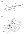
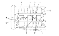
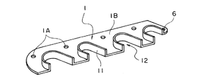
図4は本発明の帯電防止板の第2実施例を示すもので、図4(A)は帯電防止板の斜視図、図4(B)はエンジンヘッドに取り付けられた状態図である。本実施例では、イグニッションコイル2がエンジンヘッド5の頭部から突出して取り付けられた形式のものに適用された例である。したがって、本実施例のものは、向きを幾分傾斜して配設されたイグニッションコイル2と干渉しないように、イグニッションコイル収容切欠き12を4つ形成した帯電防止板1を、前記実施例のものと同様に、イグニッションコイル2の取付ボルト8を取り外した上で、取付ボルト9により帯電防止板1をエンジンヘッド5に取り付けたものである。
4A and 4B show a second embodiment of the antistatic plate of the present invention. FIG. 4A is a perspective view of the antistatic plate, and FIG. 4B is a state diagram attached to the engine head. In this embodiment, the
図5は本発明の帯電防止板の第3実施例を示すもので、本実施例のものは6気筒エンジンの3つのイグニッションコイルを配設したものに適用されたもので、ほぼ正方形のイグニッションコイル2の平面投影形状にくり抜いたイグニッションコイル収容切欠き12を3つ形成した帯電防止板1を、前記実施例のものと同様に、取付ボルト9により帯電防止板1をエンジンヘッド5に取り付けたものである。帯電防止板1の端部に形成したアース線取付部6に接続したアース線13により、バッテリ負極と直接に、あるいはバッテリ負極と導通する車体およびエンジン部に接続した。
FIG. 5 shows a third embodiment of the antistatic plate of the present invention. This embodiment is applied to a six-cylinder engine provided with three ignition coils, and is a substantially square ignition coil. The
図6は本発明の帯電防止板の第4実施例を示すもので、本実施例のものは、前記図4の第2実施例のものを基本構成としている。向きを幾分傾斜して配設されたイグニッションコイル2と干渉しないように、イグニッションコイル収容切欠き12を4つ形成した帯電防止板1における、前記イグニッションコイル収容切欠き12の周囲に、放熱フィン11が起立形成されたものである。これにより、放熱面積が増大して、さらに迅速に冷却機能が発揮される。また、放熱フィン11は、前記図1の第1実施例のものにおける放熱孔10の周囲に形成してもよい。
FIG. 6 shows a fourth embodiment of the antistatic plate according to the present invention. This embodiment has the basic structure of the second embodiment of FIG. In the
以上、本発明の実施例について説明してきたが、本発明の趣旨の範囲内にて、エンジンの形状、形式(気筒数等)、点火プラグの形状、形式、イグニッションコイルの形状、形式および点火プラグへの被冠しての装着形態ならびにエンジンヘッドへの取付形態、帯電防止板の形状すなわち、放熱孔(実施例の三角形状の他、多数のスリットや円形、楕円形、多角形等)、イグニッションコイル収容切欠き(イグニッションコイルの形状に整合)、アース線取付部(取付孔の他、ねじ突起形状等)、放熱フィン(連続壁の他、不連続状壁等)の各形状、数、形式および材質(アルミニウム、真鍮、銅等)ならびにイグニッションコイルとの共締め形態、バッテリー負極あるいはバッテリー負極と導通する車体およびエンジン部と連結されるアース線の形状、形式および材質(導電性の良好なもの)等については適宜選定することができる。 Although the embodiments of the present invention have been described above, the shape and type of the engine (number of cylinders, etc.), the shape and form of the ignition plug, the shape and form of the ignition coil, and the ignition plug are within the scope of the present invention. Attached to the head and attached to the engine head, the shape of the antistatic plate, that is, the heat radiation hole (in addition to the triangular shape of the embodiment, a number of slits, circles, ellipses, polygons, etc.), ignition Coil housing notch (matches the shape of the ignition coil), ground wire mounting part (mounting hole, screw projection shape, etc.), heat sink fin (continuous wall, discontinuous wall, etc.) And materials (aluminum, brass, copper, etc.), and a fastening form with an ignition coil, a battery negative electrode or a body connected to the battery negative electrode and an engine connected to the engine part Line shape, for the format and material (conductive good thing) and the like can be appropriately selected.
1 帯電防止板(放熱板)
1A 取付孔
1B 取付部
2 イグニッションコイル
3 取付板(負極板)
3A 取付孔
4 点火プラグ
4A ねじ部(負極)
4B 正極
5 エンジンヘッド
5A ねじ孔
6 アース線取付部
7 イグニッションコイル正極線
8 イグニッションコイル取付ボルト
9 帯電防止板取付ボルト
10 放熱孔
11 放熱フィン
12 イグニッションコイル収容切欠き
13 アース線
1 Antistatic plate (heat sink)
1A Mounting hole
3A Mounting hole 4
Claims (3)
The antistatic plate according to claim 1, wherein a heat radiating fin is formed upright around the heat radiating hole or the ignition coil housing notch.
Priority Applications (1)
| Application Number | Priority Date | Filing Date | Title |
|---|---|---|---|
| JP2004110691A JP2005291168A (en) | 2004-04-05 | 2004-04-05 | Antistatic plate |
Applications Claiming Priority (1)
| Application Number | Priority Date | Filing Date | Title |
|---|---|---|---|
| JP2004110691A JP2005291168A (en) | 2004-04-05 | 2004-04-05 | Antistatic plate |
Publications (1)
| Publication Number | Publication Date |
|---|---|
| JP2005291168A true JP2005291168A (en) | 2005-10-20 |
Family
ID=35324368
Family Applications (1)
| Application Number | Title | Priority Date | Filing Date |
|---|---|---|---|
| JP2004110691A Pending JP2005291168A (en) | 2004-04-05 | 2004-04-05 | Antistatic plate |
Country Status (1)
| Country | Link |
|---|---|
| JP (1) | JP2005291168A (en) |
Cited By (4)
| Publication number | Priority date | Publication date | Assignee | Title |
|---|---|---|---|---|
| DE102008041759A1 (en) | 2008-09-02 | 2010-03-04 | Robert Bosch Gmbh | Heat dissipating arrangement for e.g. waste heat producing electrical unit, of motor vehicle, has heat coupler formed in form of heat conducting cable or conducting strip, and thermally and directly connected with heat sink |
| JP2017187043A (en) * | 2017-07-12 | 2017-10-12 | 株式会社クボタ | Spark ignition type engine |
| US9955562B2 (en) | 2014-12-26 | 2018-04-24 | Toyota Jidosha Kabushiki Kaisha | Engine and method of production of engine |
| US10718299B2 (en) | 2014-12-25 | 2020-07-21 | Toyota Jidosha Kabushiki Kaisha | Intake system of vehicle |
-
2004
- 2004-04-05 JP JP2004110691A patent/JP2005291168A/en active Pending
Cited By (4)
| Publication number | Priority date | Publication date | Assignee | Title |
|---|---|---|---|---|
| DE102008041759A1 (en) | 2008-09-02 | 2010-03-04 | Robert Bosch Gmbh | Heat dissipating arrangement for e.g. waste heat producing electrical unit, of motor vehicle, has heat coupler formed in form of heat conducting cable or conducting strip, and thermally and directly connected with heat sink |
| US10718299B2 (en) | 2014-12-25 | 2020-07-21 | Toyota Jidosha Kabushiki Kaisha | Intake system of vehicle |
| US9955562B2 (en) | 2014-12-26 | 2018-04-24 | Toyota Jidosha Kabushiki Kaisha | Engine and method of production of engine |
| JP2017187043A (en) * | 2017-07-12 | 2017-10-12 | 株式会社クボタ | Spark ignition type engine |
Similar Documents
| Publication | Publication Date | Title |
|---|---|---|
| WO2022039948A9 (en) | Spark plug with thermally coupled center electrode | |
| JPS5842620Y2 (en) | plasma igniter | |
| US20100072874A1 (en) | Spark plug | |
| JP2006009782A (en) | Multiple discharge ignition system | |
| JP2010118236A (en) | Spark plug of internal combustion engine | |
| JP2009026489A (en) | Plasma ignition device | |
| JPH10176647A (en) | Ignition coil | |
| JP2009146636A (en) | Ignition device | |
| US5181498A (en) | Ignition apparatus for an internal combustion engine | |
| US7124725B2 (en) | Engine spark plug grounding structure, grounding wiring apparatus, and grounding wiring method | |
| JPH08232825A (en) | Ignition device with integrated combustion pressure sensor | |
| JP2014239000A (en) | Spark plug for internal combustion engine | |
| JP2004122871A (en) | Power supply circuit for automobile | |
| US7140359B2 (en) | Spark plug capable of removing remaining electric charges | |
| JP2771240B2 (en) | Mounting structure of outboard motor charger | |
| JP2009176504A (en) | Spark plug | |
| KR101749685B1 (en) | spark plug | |
| US9059572B2 (en) | Spark plug with center electrode for internal combustion engine | |
| KR102592168B1 (en) | Converter | |
| JP3109380U (en) | Spark plug that can remove residual electricity | |
| JPH08121308A (en) | In-cylinder pressure sensor integrated ignition device | |
| JP2864750B2 (en) | Ignition device for internal combustion engine | |
| JPS591108Y2 (en) | internal combustion engine ignition system | |
| US7320317B2 (en) | Auxiliary device for engine spark plug ignition | |
| EP2978086B1 (en) | Ignition apparatus, ignition plug, and engine using said apparatus and plug |