US10718299B2 - Intake system of vehicle - Google Patents

Intake system of vehicle Download PDF

Info

Publication number
US10718299B2
US10718299B2 US14/979,664 US201514979664A US10718299B2 US 10718299 B2 US10718299 B2 US 10718299B2 US 201514979664 A US201514979664 A US 201514979664A US 10718299 B2 US10718299 B2 US 10718299B2
Authority
US
United States
Prior art keywords
air
cleaner case
air cleaner
discharge type
self discharge
Prior art date
Legal status (The legal status is an assumption and is not a legal conclusion. Google has not performed a legal analysis and makes no representation as to the accuracy of the status listed.)
Active, expires
Application number
US14/979,664
Other versions
US20160186703A1 (en
Inventor
Toshio Tanahashi
Yoji Kanehara
Koshi Yamada
Current Assignee (The listed assignees may be inaccurate. Google has not performed a legal analysis and makes no representation or warranty as to the accuracy of the list.)
Toyota Motor Corp
Original Assignee
Toyota Motor Corp
Priority date (The priority date is an assumption and is not a legal conclusion. Google has not performed a legal analysis and makes no representation as to the accuracy of the date listed.)
Filing date
Publication date
Application filed by Toyota Motor Corp filed Critical Toyota Motor Corp
Assigned to TOYOTA JIDOSHA KABUSHIKI KAISHA reassignment TOYOTA JIDOSHA KABUSHIKI KAISHA ASSIGNMENT OF ASSIGNORS INTEREST (SEE DOCUMENT FOR DETAILS). Assignors: KANEHARA, YOJI, TANAHASHI, TOSHIO, YAMADA, KOSHI
Publication of US20160186703A1 publication Critical patent/US20160186703A1/en
Application granted granted Critical
Publication of US10718299B2 publication Critical patent/US10718299B2/en
Active legal-status Critical Current
Adjusted expiration legal-status Critical

Links

Images

Classifications

    • FMECHANICAL ENGINEERING; LIGHTING; HEATING; WEAPONS; BLASTING
    • F02COMBUSTION ENGINES; HOT-GAS OR COMBUSTION-PRODUCT ENGINE PLANTS
    • F02MSUPPLYING COMBUSTION ENGINES IN GENERAL WITH COMBUSTIBLE MIXTURES OR CONSTITUENTS THEREOF
    • F02M35/00Combustion-air cleaners, air intakes, intake silencers, or induction systems specially adapted for, or arranged on, internal-combustion engines
    • F02M35/10Air intakes; Induction systems
    • FMECHANICAL ENGINEERING; LIGHTING; HEATING; WEAPONS; BLASTING
    • F02COMBUSTION ENGINES; HOT-GAS OR COMBUSTION-PRODUCT ENGINE PLANTS
    • F02MSUPPLYING COMBUSTION ENGINES IN GENERAL WITH COMBUSTIBLE MIXTURES OR CONSTITUENTS THEREOF
    • F02M35/00Combustion-air cleaners, air intakes, intake silencers, or induction systems specially adapted for, or arranged on, internal-combustion engines
    • F02M35/02Air cleaners
    • F02M35/0217Air cleaners acting by electric discharge; Electrostatic precipitators therefor
    • BPERFORMING OPERATIONS; TRANSPORTING
    • B01PHYSICAL OR CHEMICAL PROCESSES OR APPARATUS IN GENERAL
    • B01DSEPARATION
    • B01D46/00Filters or filtering processes specially modified for separating dispersed particles from gases or vapours
    • B01D46/0002Casings; Housings; Frame constructions
    • BPERFORMING OPERATIONS; TRANSPORTING
    • B01PHYSICAL OR CHEMICAL PROCESSES OR APPARATUS IN GENERAL
    • B01DSEPARATION
    • B01D46/00Filters or filtering processes specially modified for separating dispersed particles from gases or vapours
    • B01D46/42Auxiliary equipment or operation thereof
    • B01D46/4209Prevention of static charge, e.g. by grounding
    • FMECHANICAL ENGINEERING; LIGHTING; HEATING; WEAPONS; BLASTING
    • F02COMBUSTION ENGINES; HOT-GAS OR COMBUSTION-PRODUCT ENGINE PLANTS
    • F02MSUPPLYING COMBUSTION ENGINES IN GENERAL WITH COMBUSTIBLE MIXTURES OR CONSTITUENTS THEREOF
    • F02M35/00Combustion-air cleaners, air intakes, intake silencers, or induction systems specially adapted for, or arranged on, internal-combustion engines
    • F02M35/02Air cleaners
    • F02M35/0201Housings; Casings; Frame constructions; Lids; Manufacturing or assembling thereof
    • F02M35/0205Details, e.g. sensors or measuring devices
    • FMECHANICAL ENGINEERING; LIGHTING; HEATING; WEAPONS; BLASTING
    • F02COMBUSTION ENGINES; HOT-GAS OR COMBUSTION-PRODUCT ENGINE PLANTS
    • F02MSUPPLYING COMBUSTION ENGINES IN GENERAL WITH COMBUSTIBLE MIXTURES OR CONSTITUENTS THEREOF
    • F02M35/00Combustion-air cleaners, air intakes, intake silencers, or induction systems specially adapted for, or arranged on, internal-combustion engines
    • F02M35/02Air cleaners
    • F02M35/024Air cleaners using filters, e.g. moistened
    • HELECTRICITY
    • H01ELECTRIC ELEMENTS
    • H01TSPARK GAPS; OVERVOLTAGE ARRESTERS USING SPARK GAPS; SPARKING PLUGS; CORONA DEVICES; GENERATING IONS TO BE INTRODUCED INTO NON-ENCLOSED GASES
    • H01T19/00Devices providing for corona discharge
    • HELECTRICITY
    • H05ELECTRIC TECHNIQUES NOT OTHERWISE PROVIDED FOR
    • H05FSTATIC ELECTRICITY; NATURALLY-OCCURRING ELECTRICITY
    • H05F3/00Carrying-off electrostatic charges
    • H05F3/04Carrying-off electrostatic charges by means of spark gaps or other discharge devices
    • FMECHANICAL ENGINEERING; LIGHTING; HEATING; WEAPONS; BLASTING
    • F02COMBUSTION ENGINES; HOT-GAS OR COMBUSTION-PRODUCT ENGINE PLANTS
    • F02MSUPPLYING COMBUSTION ENGINES IN GENERAL WITH COMBUSTIBLE MIXTURES OR CONSTITUENTS THEREOF
    • F02M35/00Combustion-air cleaners, air intakes, intake silencers, or induction systems specially adapted for, or arranged on, internal-combustion engines
    • F02M35/10Air intakes; Induction systems
    • F02M35/10314Materials for intake systems
    • F02M35/10321Plastics; Composites; Rubbers
    • FMECHANICAL ENGINEERING; LIGHTING; HEATING; WEAPONS; BLASTING
    • F02COMBUSTION ENGINES; HOT-GAS OR COMBUSTION-PRODUCT ENGINE PLANTS
    • F02MSUPPLYING COMBUSTION ENGINES IN GENERAL WITH COMBUSTIBLE MIXTURES OR CONSTITUENTS THEREOF
    • F02M35/00Combustion-air cleaners, air intakes, intake silencers, or induction systems specially adapted for, or arranged on, internal-combustion engines
    • F02M35/10Air intakes; Induction systems
    • F02M35/10314Materials for intake systems
    • F02M35/10327Metals; Alloys

Definitions

  • the invention relates to an intake system of a vehicle.
  • a vehicle is publicly known, in which a discharge device such as a discharge antenna is mounted on an engine or an engine-related member of the vehicle, and high-voltage electricity, static electricity and so on generated and charged in the engine area is discharged and emitted outside, thereby improving fuel economy (for example, see Japanese Patent Application Publication No. 5-238438 (JP 5-238438 A)).
  • JP 5-238438 A it is known that static electricity is charged to a vehicle, and that static electricity charged to a vehicle have some kind of influence on driving of the vehicle.
  • specifically why and how the static electricity charged to a vehicle affects driving of the vehicle is not known for sure.
  • without clearly knowing specifically why and how static electricity charged to a vehicle affects driving of the vehicle it is not possible to appropriately deal with static electricity charged to a vehicle.
  • the inventors paid attention especially to an air cleaner, and pursued specifically why and how static electricity charged to an air cleaner affects driving of a vehicle.
  • the inventors found that static electricity charged to an air filter of an air cleaner greatly affects intake efficiency of intake air, and also found an adequate static elimination method required for improving intake efficiency of intake air based on the fact found.
  • An intake system of a vehicle includes an air cleaner case, an air filter that is arranged inside the air cleaner case and positively charged, and a self discharge type static eliminator that decreases an amount of electrification charge on a wall surface of the air cleaner case within a limited range about a location where the self discharge type static eliminator is installed, when the self discharge type static eliminator is installed on the wall surface of the air cleaner case.
  • a peripheral edge part of the air filter is held by an air filter holding part of the air cleaner case.
  • the self discharge type static eliminator is installed on an outer wall surface of the air filter holding part of the air cleaner case.
  • the air cleaner case may include an air inflow-side air cleaner case and an air outflow-side air cleaner case, and the peripheral edge part of the air filter may be held at a connecting part between the air inflow-side air cleaner case and the air outflow-side air cleaner case.
  • the self discharge type static eliminator may be installed on an outer wall surface of the connecting part between the air inflow-side air cleaner case and the air outflow-side air cleaner case.
  • the air inflow-side air cleaner case and the air outflow-side air cleaner case may be provided with connection flanges, respectively, in the connection part between the air inflow-side air cleaner case and the air outflow-side air cleaner case.
  • the connection flanges project outwardly from an outer wall surface of the air inflow-side air cleaner case and an outer wall surface of the air outflow-side air cleaner case, respectively.
  • the peripheral edge part of the air filter may be held between the connection flange of the air inflow-side air cleaner case and the connection flange of the air outflow-side air cleaner case.
  • the self discharge type static eliminator may be installed on at least one of an outer wall surface of the connection flange of the air inflow-side air cleaner case, and an outer wall surface of the connection flange of the air outflow-side air cleaner case.
  • the air filter may include filter paper and a filter paper support frame that supports a periphery of the filter paper, and the filter paper support frame may be held between the connection flange of the air inflow-side air cleaner case and the connection flange of the air outflow-side air cleaner case.
  • the air cleaner case may be made from a non-conductive synthetic resin material.
  • the self discharge type static eliminator may be metallic foil that is adhered onto a wall surface of the air cleaner case by a conductive adhesive.
  • the self discharge type static eliminator may have a corner part.
  • the self discharge type static eliminator may have a long and narrow rectangular flat plate shape.
  • the self discharge type static eliminator may be formed integrally on a wall surface of the air cleaner case.
  • FIG. 1 is an exploded perspective view of an air cleaner
  • FIG. 2 is a bottom view of an air inflow-side air cleaner case shown in FIG. 1 ;
  • FIG. 3 is a top view of an air outflow-side air cleaner case shown in FIG. 1 ;
  • FIG. 4 is a partial enlarged sectional view of the air cleaner, taken along the line A-A in FIG. 2 ;
  • FIG. 7A is a view showing a self discharge type static eliminator
  • FIG. 7B is a view showing the self discharge type static eliminator
  • FIG. 7C is a view showing a self discharge type static eliminator
  • FIG. 8A is a view for explaining a static elimination effect by the self discharge type static eliminator
  • FIG. 8B is a view for explaining the static elimination effect by the self discharge type static eliminator elimination effect
  • FIG. 8C is a view for explaining the static elimination effect by the self discharge type static eliminator
  • FIG. 9A is a view for explaining a self discharge effect
  • FIG. 9B is a view for explaining the self discharge effect
  • FIG. 10A is an exploded perspective view of an air cleaner according to another example
  • FIG. 10B is an exploded perspective view of an air cleaner according to another example.
  • FIG. 1 shows an exploded perspective view of an air cleaner.
  • reference numeral 1 shows an air inflow-side air cleaner case having an outside air inlet 1 a
  • reference numeral 2 shows an air outflow-side air cleaner case having an air outflow port 2 a
  • an air cleaner case is structured from the air inflow-side air cleaner case 1 and the air outflow-side air cleaner case 2 .
  • the air inflow-side air cleaner case 1 and the air outflow-side air cleaner case 2 , or the air cleaner case is formed from a non-conductive synthetic resin material.
  • reference numeral 3 shows an air filter.
  • the air filter 3 is made from convoluted filter paper 4 and a filter paper support frame 5 that supports the periphery of the filter paper 4 throughout the entire circumference.
  • the filter paper support frame 5 is formed from a rubber material.
  • connection flange 6 is formed in an upper end part of the air inflow-side air cleaner case 1 throughout the entire circumference of the upper end part.
  • the connection flange 6 projects outwardly from an outer wall surface of the upper end part of the air inflow-side air cleaner case 1 .
  • An connection flange 7 is formed in a lower end part of the air outflow-side air cleaner case 2 throughout the entire circumference of the lower end part. The connection flange 7 projects outwardly from an outer wall surface of the lower end part of the air outflow-side air cleaner case 2 .
  • FIG. 4 shows a partial enlarged sectional view of the air cleaner case integrated as stated above. The sectional view is taken along the line A-A in FIG. 2 .
  • FIG. 2 shows a bottom view of the air inflow-side air cleaner case 1 , which is a view of the air inflow-side air cleaner case 1 in FIG. 1 seen from the bottom.
  • FIG. 3 is a plan view of the air outflow-side air cleaner case 2 , which is a view of the air outflow-side air cleaner case 2 in FIG. 1 seen from the top.
  • FIG. 6A shows a case where air flows along a surface of a thin wall 9 that is positively charged. In this case, since air tends to be positively charged, FIG. 6A shows a case where positively-charged air flows along the surface of the thin wall 9 that is positively charged.
  • FIG. 6A shows a case where positively-charged air flows along the surface of the thin wall 9 that is positively charged.
  • solid-line arrows show a case where a voltage value on the surface of the thin wall 9 is low, and, in this case, air flows along the surface of the thin wall 9 .
  • broken-line arrows show a case where a voltage value on the surface of the thin wall 9 is high, and, in this case, air flows so as to be separated from the surface of the thin wall 9 at a point where the surface of the thin wall 9 curves downwardly, or a point where the air flow is easily separated from the surface of the thin wall 9 .
  • the air flow is not separated when the surface of the thin wall 9 is not positively charged.
  • an air flow could be separated when the surface of the thin wall 9 is positively charged.
  • a degree of separation of an air flow is greater than that in the case where the surface of the thin wall 9 is not positively charged. In this way, it is confirmed that, when the surface of the thin wall 9 is positively charged, an air flow is separated from the surface of the thin wall 9 or separation of air happens based on electrical repulsive force.
  • FIG. 7C show examples of this self discharge type static eliminator.
  • FIG. 7A and FIG. 7B show a plan view and a side sectional view of a typical self discharge type static eliminator 10 , respectively.
  • FIG. 7C shows a side sectional view of another self discharge type static eliminator 10 .
  • the self discharge type static eliminator 10 has a long and narrow rectangular flat plate shape, and is also formed from metallic foil 11 that is adhered onto the surface of the thin wall 9 by a conductive adhesive 12 .
  • the self discharge type static eliminator 10 is made from a conductive thin film that is formed integrally with the surface of the thin wall 9 .
  • static elimination of the air filter 3 is performed by using the self discharge type static eliminator 10 .
  • FIG. 8A shows a case where the self discharge type static eliminator 10 shown in FIG. 7A and FIG. 7B is installed on the surface of the thin wall 9 .
  • the self discharge type static eliminator 10 is installed on the surface of the thin wall 9 as stated above, an amount of electrification charge of the surface of the thin wall 9 is reduced within a limited range shown by a broken line about the location where the self discharge type static eliminator 10 is installed as shown in FIG. 8B .
  • FIG. 8C shows a case where the self discharge type static eliminator 10 is installed in the vicinity of an end part 9 a of the thin wall 9 .
  • the thin wall 9 is formed from a non-conductive synthetic resin material.
  • the thin wall 9 is formed from a non-conductive synthetic resin material as stated above, inside of the thin wall 9 is not charged, and the surface of the thin wall 9 is charged. It is confirmed that both the surface and rear surface of the air cleaner cases 1 , 2 shown in FIG. 1 are charged positively.
  • FIG. 9A shows a case where both the surface and the rear surface of the thin wall 9 are positively charged.
  • the self discharge type static eliminator 10 is the metallic foil 11 adhered to the surface of the thin wall 9 by the conductive adhesive 12 . Since both the metallic foil 11 and the conductive adhesive 12 have conductivity, inside of the metallic foil 11 , that means inside of the self discharge type static eliminator 10 , is positively charged.
  • Voltage of the self discharge type static eliminator 10 is about the same as voltage on the surface of the thin wall 9 around the self discharge type static eliminator 10 . Therefore, the voltage of the self discharge type static eliminator 10 is quite high. Meanwhile, because air tends to be positively charged as stated earlier, positive air ions (expressed as + in a circle) are present in a part of air. In this case, in comparison between electrical potential of the air ion, and electrical potential of the self discharge type static eliminator 10 , the electrical potential of the self discharge type static eliminator 10 is much higher than the electrical potential of the air ion. Therefore, when the air ion comes close to, for example, a corner part 13 of the self discharge type static eliminator 10 as shown in FIG. 9B , a field intensity increases between the air ion and the corner part 13 of the self discharge type static eliminator 10 . As a result, discharge happens between the air ion and the corner part 13 of the self discharge type static eliminator 10 .
  • an air ion with an increased positive charge amount (expressed as ++ in a circle) is generated as shown in FIG. 9B , and the air ion with the increased positive charge amount is dispersed into circumambient air.
  • the amount of air ions with the increased positive charge amount is extremely smaller than the amount of air flowing around the self discharge type static eliminator 10 .
  • Discharge between an air ion and the self discharge type static eliminator 10 happens between the air ion and the corner part 13 of the self discharge type static eliminator 10 , or between the air ion and sharp end parts 14 in a peripheral part of the self discharge type static eliminator 10 . Therefore, in order to make discharge happen easily between an air ion and the self discharge type static eliminator 10 , it is preferred that a number of sharp end parts 14 are formed, in addition to the corner part 13 , in the peripheral part of the self discharge type static eliminator 10 . Hence, when fabricating the self discharge type static eliminator 10 , it is preferred that metallic foil is cut so that burrs like the sharp end parts 14 are made in the section when fabricating the metallic foil 11 by cutting large metallic foil.
  • the metallic foil 11 of the self discharge type static eliminator 10 shown in FIG. 7A and FIG. 7B is made from ductile metal such as aluminum or copper.
  • the metallic foil 11 in the example according to the invention is aluminum foil.
  • a longitudinal length of the aluminum foil 11 used in the example according to the invention is between about 50 mm and 100 mm, and a thickness is between about 0.05 mm and 0.2 mm.
  • a diameter D of the limited range shown by the broken line in FIG. 8B in which voltage is reduced, is between about 150 mm and 200 mm.
  • An aluminum tape, in which a layer of conductive adhesive 12 is formed on the aluminum foil 11 may be cut and used as the self discharge type static eliminator 10 . Further, as shown in FIG.
  • the self discharge type static eliminator 10 may be structured from a conductive thin film that is formed integrally with the surface of the thin wall 9 .
  • a number of sharp end parts 14 are formed, in addition to the corner part 13 , in a peripheral part of the conductive thin film as shown in FIG. 9B .
  • FIG. 5A and FIG. 5B show enlarged views of sections of the filter paper 4
  • reference numeral 8 in FIG. 5A and FIG. 5B shows fiber that structures the filter paper 4
  • FIG. 5B shows a flow of intake air when voltage of the filter paper 4 is low, and, intake air in this case flows along a peripheral wall surface of the fiber 8 as shown by arrows.
  • the self discharge type static eliminator 10 is installed on the outer wall surface of the air filter holding part of the air cleaner case in order to reduce voltage of the filter paper 4 .
  • the self discharge type static eliminators 10 are installed on an outer wall surface of the connection flange 6 of the air inflow-side air cleaner case 1 as shown in FIG. 2 and FIG. 4 .
  • the inner wall surface portions are in contact with the filter paper 4 or the filter paper support frame 5 .
  • the location is on the outer wall surface of the air filter holding part of the air cleaner case. Therefore, in the invention, the self discharge type static eliminator 10 is installed on the outer wall surface of the air filter holding part of the air cleaner case.
  • the air inflow-side air cleaner case 1 and the air outflow-side air cleaner case 2 have the connection flanges 6 , 7 , respectively, in the connecting part between the air inflow-side air cleaner case 1 and the air outflow-side air cleaner case 2 as shown in FIG. 4 .
  • the connection flanges 6 , 7 project outwardly from the outer wall surface of the air inflow-side air cleaner case 1 and the outer wall surface of the air outflow-side air cleaner case 2 , respectively.
  • the plurality of self discharge type static eliminators 10 are installed at an equal interval on the outer wall surface of the connection flange 6 of the air inflow-side air cleaner case 1 .
  • the plurality of self discharge type static eliminators 10 are installed at an equal interval on the outer wall surface of the connection flange 7 of the air outflow-side air cleaner case 2 .
  • FIG. 10A shows an exploded perspective view of an air cleaner that is formed integrally with a cylinder head cover.
  • the air cleaner is structured from an air inflow-side air cleaner case 21 that is formed integrally with a cylinder head cover 20 made from a non-conductive synthetic resin, an air outflow-side air cleaner case 22 made from a non-conductive synthetic resin material, and an air filter 23 .
  • a peripheral edge part of the air filter 23 is also held between a connection flange 24 of the air inflow-side air cleaner case 21 and a connection flange 25 of the air outflow-side air cleaner case 22 .
  • a self discharge type static eliminator 10 is installed on an outer wall surface of the connection flange 24 of the air inflow-side air cleaner case 21 .
  • the self discharge type static eliminator 10 is installed on an outer wall surface of the connection flange 25 of the air outflow-side air cleaner case 22 .
  • a self discharge type static eliminator 10 is installed on an outer wall surface of the connection flange 34 of the air inflow-side air cleaner case 31 .
  • the self discharge type static eliminator 10 is installed on an outer wall surface of the connection flange 35 of the air outflow-side air cleaner case 32 .

Abstract

An intake system of a vehicle, includes an air cleaner case, an air filter that is arranged inside the air cleaner case and positively charged, and a self discharge type static eliminator that decreases an amount of electrification charge on a wall surface of the air cleaner case within a limited range about a location where the self discharge type static eliminator is installed, when the self discharge type static eliminator is installed on the wall surface of the air cleaner case. An peripheral edge part of the air filter is held by an air filter holding part of the air cleaner case. The self discharge type static eliminator is installed on an outer wall surface of the air filter holding part of the air cleaner case.

Description

INCORPORATION BY REFERENCE
The disclosure of Japanese Patent Application No. 2014-263679 filed on Dec. 25, 2014 including the specification, drawings and abstract is incorporated herein by reference in its entirety.
BACKGROUND OF THE INVENTION
1. Field of the Invention
The invention relates to an intake system of a vehicle.
2. Description of Related Art
A vehicle is publicly known, in which a discharge device such as a discharge antenna is mounted on an engine or an engine-related member of the vehicle, and high-voltage electricity, static electricity and so on generated and charged in the engine area is discharged and emitted outside, thereby improving fuel economy (for example, see Japanese Patent Application Publication No. 5-238438 (JP 5-238438 A)).
SUMMARY OF THE INVENTION
As described in JP 5-238438 A, it is known that static electricity is charged to a vehicle, and that static electricity charged to a vehicle have some kind of influence on driving of the vehicle. However, specifically why and how the static electricity charged to a vehicle affects driving of the vehicle is not known for sure. However, without clearly knowing specifically why and how static electricity charged to a vehicle affects driving of the vehicle, it is not possible to appropriately deal with static electricity charged to a vehicle.
Therefore, the inventors paid attention especially to an air cleaner, and pursued specifically why and how static electricity charged to an air cleaner affects driving of a vehicle. As a result of the pursuit, the inventors found that static electricity charged to an air filter of an air cleaner greatly affects intake efficiency of intake air, and also found an adequate static elimination method required for improving intake efficiency of intake air based on the fact found.
An intake system of a vehicle according to an aspect of the invention includes an air cleaner case, an air filter that is arranged inside the air cleaner case and positively charged, and a self discharge type static eliminator that decreases an amount of electrification charge on a wall surface of the air cleaner case within a limited range about a location where the self discharge type static eliminator is installed, when the self discharge type static eliminator is installed on the wall surface of the air cleaner case. A peripheral edge part of the air filter is held by an air filter holding part of the air cleaner case. The self discharge type static eliminator is installed on an outer wall surface of the air filter holding part of the air cleaner case.
By installing the self discharge type static eliminator on the outer wall surface of the air filter holding part of the air cleaner case, static elimination of the air filter is performed. Thus, intake efficiency of intake air is improved significantly.
In the foregoing aspect, the air cleaner case may include an air inflow-side air cleaner case and an air outflow-side air cleaner case, and the peripheral edge part of the air filter may be held at a connecting part between the air inflow-side air cleaner case and the air outflow-side air cleaner case. The self discharge type static eliminator may be installed on an outer wall surface of the connecting part between the air inflow-side air cleaner case and the air outflow-side air cleaner case.
In the foregoing structure, the air inflow-side air cleaner case and the air outflow-side air cleaner case may be provided with connection flanges, respectively, in the connection part between the air inflow-side air cleaner case and the air outflow-side air cleaner case. The connection flanges project outwardly from an outer wall surface of the air inflow-side air cleaner case and an outer wall surface of the air outflow-side air cleaner case, respectively. The peripheral edge part of the air filter may be held between the connection flange of the air inflow-side air cleaner case and the connection flange of the air outflow-side air cleaner case. The self discharge type static eliminator may be installed on at least one of an outer wall surface of the connection flange of the air inflow-side air cleaner case, and an outer wall surface of the connection flange of the air outflow-side air cleaner case.
In the foregoing structure, the air filter may include filter paper and a filter paper support frame that supports a periphery of the filter paper, and the filter paper support frame may be held between the connection flange of the air inflow-side air cleaner case and the connection flange of the air outflow-side air cleaner case.
In the foregoing aspect, the air cleaner case may be made from a non-conductive synthetic resin material.
In the foregoing aspect, the self discharge type static eliminator may be metallic foil that is adhered onto a wall surface of the air cleaner case by a conductive adhesive.
In the foregoing structure, the self discharge type static eliminator may have a corner part.
In the foregoing structure, the self discharge type static eliminator may have a long and narrow rectangular flat plate shape.
In the foregoing structure, the self discharge type static eliminator may have a sharp end part.
In the foregoing structure, the self discharge type static eliminator may be formed integrally on a wall surface of the air cleaner case.
According to the above structure, it is possible to obtain effects similar to those obtained in the foregoing aspect.
BRIEF DESCRIPTION OF THE DRAWINGS
Features, advantages, and technical and industrial significance of exemplary embodiments of the invention will be described below with reference to the accompanying drawings, in which like numerals denote like elements, and wherein:
FIG. 1 is an exploded perspective view of an air cleaner;
FIG. 2 is a bottom view of an air inflow-side air cleaner case shown in FIG. 1;
FIG. 3 is a top view of an air outflow-side air cleaner case shown in FIG. 1;
FIG. 4 is a partial enlarged sectional view of the air cleaner, taken along the line A-A in FIG. 2;
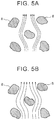
FIG. 5A is a view for explaining an intake air flow within filter paper of an air filter, and FIG. 5B is a view for explaining an intake air flow within the filter paper of the air filter;
FIG. 6A is a view for explaining a change of an intake air flow, and FIG. 6B is a view for explaining the change of the intake air flow;
FIG. 7A is a view showing a self discharge type static eliminator, FIG. 7B is a view showing the self discharge type static eliminator, and FIG. 7C is a view showing a self discharge type static eliminator;
FIG. 8A is a view for explaining a static elimination effect by the self discharge type static eliminator; FIG. 8B is a view for explaining the static elimination effect by the self discharge type static eliminator elimination effect, and FIG. 8C is a view for explaining the static elimination effect by the self discharge type static eliminator;
FIG. 9A is a view for explaining a self discharge effect, and FIG. 9B is a view for explaining the self discharge effect; and
FIG. 10A is an exploded perspective view of an air cleaner according to another example, and FIG. 10B is an exploded perspective view of an air cleaner according to another example.
DETAILED DESCRIPTION OF EMBODIMENTS
FIG. 1 shows an exploded perspective view of an air cleaner. With reference to FIG. 1, reference numeral 1 shows an air inflow-side air cleaner case having an outside air inlet 1 a, reference numeral 2 shows an air outflow-side air cleaner case having an air outflow port 2 a. In short, in the air cleaner shown in FIG. 1, an air cleaner case is structured from the air inflow-side air cleaner case 1 and the air outflow-side air cleaner case 2. The air inflow-side air cleaner case 1 and the air outflow-side air cleaner case 2, or the air cleaner case, is formed from a non-conductive synthetic resin material. Meanwhile, in FIG. 1, reference numeral 3 shows an air filter. The air filter 3 is made from convoluted filter paper 4 and a filter paper support frame 5 that supports the periphery of the filter paper 4 throughout the entire circumference. In the example shown in FIG. 1, the filter paper support frame 5 is formed from a rubber material.
As shown in FIG. 1, a connection flange 6 is formed in an upper end part of the air inflow-side air cleaner case 1 throughout the entire circumference of the upper end part. The connection flange 6 projects outwardly from an outer wall surface of the upper end part of the air inflow-side air cleaner case 1. An connection flange 7 is formed in a lower end part of the air outflow-side air cleaner case 2 throughout the entire circumference of the lower end part. The connection flange 7 projects outwardly from an outer wall surface of the lower end part of the air outflow-side air cleaner case 2. The air inflow-side air cleaner case 1 and the air outflow-side air cleaner case 2 are integrated with each other by fastening the connection flanges 6, 7 of the air inflow-side air cleaner case 1 and the air outflow-side air cleaner case 2 to each other. FIG. 4 shows a partial enlarged sectional view of the air cleaner case integrated as stated above. The sectional view is taken along the line A-A in FIG. 2.
As this time, as seen in FIG. 4, the filter paper support frame 5, or a peripheral edge part of the air filter 3, is held between the connection flange 6 of the air inflow-side air cleaner case 1 and the connection flange 7 of the air outflow-side air cleaner case 2. As shown in FIG. 4, a flange end part 6 a extends upwardly or towards the connection flange 7 from an outer peripheral edge of the connection flange 6. A flange end part 7 a extends downwardly from an outer peripheral edge of the connection flange 7 so as to cover an outer peripheral surface of the flange end part 6 a.
Once driving of an engine begins, outside air is drawn into the air inflow-side air cleaner case 1 from the outside air inlet 1 a. Then, the outside air, or air, passes through the filter paper 4 and is drawn into the air outflow-side air cleaner case 2. Thereafter, the outside air passes through the air outflow port 2 a and is drawn into an air intake system of the engine, for example, a surge tank. FIG. 2 shows a bottom view of the air inflow-side air cleaner case 1, which is a view of the air inflow-side air cleaner case 1 in FIG. 1 seen from the bottom. FIG. 3 is a plan view of the air outflow-side air cleaner case 2, which is a view of the air outflow-side air cleaner case 2 in FIG. 1 seen from the top.
Once a vehicle is run, each part of tires comes into contact with and is separated from a road surface repeatedly, and static electricity is thus generated. Static electricity is also generated as components of the engine, and components of a braking device move relative to each other. Further, static electricity is generated due to air that flows on and is in frictional contact with an outer peripheral surface of the vehicle when the vehicle is running. Because of the static electricity generated as above, the vehicle's body, engine, and so on of the vehicle are charged, and an air cleaner is also charged. In such a case, it is confirmed that a surface of the air cleaner case made from a non-conductive synthetic resin material, that means surfaces of the air inflow-side air cleaner case 1 and the air outflow-side air cleaner case 2, as well as the air filter 3 are positively charged. Moreover, it is confirmed that there are instances where a voltage value of the surfaces of the air cleaner cases 1, 2 and the air filter 3 is a voltage as high as 1000 (v) or higher.
It is confirmed that, when a voltage value becomes high on a surface of a thin wall made from a non-conductive synthetic resin material, a flow of air along the surface of the thin wall changes. Thus, to begin with, explanation is given about phenomena confirmed by the inventors with regard to how an air flow along the surface of the thin wall changes in accordance with a voltage value on the surface of the thin wall. FIG. 6A shows a case where air flows along a surface of a thin wall 9 that is positively charged. In this case, since air tends to be positively charged, FIG. 6A shows a case where positively-charged air flows along the surface of the thin wall 9 that is positively charged. In FIG. 6A, solid-line arrows show a case where a voltage value on the surface of the thin wall 9 is low, and, in this case, air flows along the surface of the thin wall 9. On the contrary, broken-line arrows show a case where a voltage value on the surface of the thin wall 9 is high, and, in this case, air flows so as to be separated from the surface of the thin wall 9 at a point where the surface of the thin wall 9 curves downwardly, or a point where the air flow is easily separated from the surface of the thin wall 9.
FIG. 6B shows measured values of a velocity ratio U/U, at point X (FIG. 6A), between a flow velocity U of a main flow of air that flows along the surface of the thin wall 9 in FIG. 6A, and a flow velocity U at a point away from the surface of the thin wall 9 by a distance S. Each point shown by a black rhombus in FIG. 6B shows a case where the surface of the thin wall 9 is not positively charged, and each point shown by a black quadrangle in FIG. 6B shows a case where the surface of the thin wall 9 is positively charged. It is understood from FIG. 6B that, in the case where the surface of the thin wall 9 is positively charged, a velocity boundary layer is separated more from the surface of the thin wall 9 compared to the case where the surface the thin wall 9 is not positively charged. Therefore, in the case where the surface of the thin wall 9 is positively charged, air flows so as to be separated from the surface of the thin wall 9 as shown by broken-line arrows in FIG. 6A.
As stated above, air tends to be positively charged. Therefore, positive air ions (expressed as + in a circle) are present in a part of air. Accordingly, when the surface of the thin wall 9 is positively charged, repulsive force acts between the positive air ions and the surface of the thin wall 9. Thus, as shown by the broken-line arrows in FIG. 6A, air flows so as to be separated from the surface of the thin wall 9 at the point where the surface of the thin wall 9 is curved downwardly, or the point where the air flow is easily separated from the surface of the thin wall 9. It is confirmed from an experiment that an air flow along the surface of the thin wall 9 is separated from the surface of the thin wall 9 because of positive charge on the surface of the thin wall 9. In this case, it is known that the higher the voltage value becomes on the surface of the thin wall 9, the more the air flow along the surface of the thin wall 9 is separated from the surface of the thin wall 9.
In a case where the surface of the thin wall 9 has a shape that easily causes separation of the air flow, the air flow is not separated when the surface of the thin wall 9 is not positively charged. However, it is confirmed that an air flow could be separated when the surface of the thin wall 9 is positively charged. It is also confirmed that, when the surface of the thin wall 9 is positively charged, a degree of separation of an air flow is greater than that in the case where the surface of the thin wall 9 is not positively charged. In this way, it is confirmed that, when the surface of the thin wall 9 is positively charged, an air flow is separated from the surface of the thin wall 9 or separation of air happens based on electrical repulsive force.
As stated above, when the surface of the thin wall 9 is positively charged, an air flow becomes different from a flow that is originally intended. In this case, once positive charge on the surface of the thin wall 9 is entirely or partially eliminated, or static elimination of the surface of the thin wall 9 is performed, to decrease the voltage value of the surface of the thin wall 9, it is possible to bring the air flow along the surface of the thin wall 9 back to an air flow in the case where the surface of the thin wall 9 is not positively charged. This means that, by the static elimination, the air flow is restored to an air flow that is originally intended. Thus, the inventors considered an easy static elimination method for restoring an air flow to one originally intended, and found an easy static elimination method using a self discharge type static eliminator. FIG. 7A to FIG. 7C show examples of this self discharge type static eliminator. FIG. 7A and FIG. 7B show a plan view and a side sectional view of a typical self discharge type static eliminator 10, respectively. FIG. 7C shows a side sectional view of another self discharge type static eliminator 10.
In the example shown in FIG. 7A and FIG. 7B, the self discharge type static eliminator 10 has a long and narrow rectangular flat plate shape, and is also formed from metallic foil 11 that is adhered onto the surface of the thin wall 9 by a conductive adhesive 12. Meanwhile, in the example shown in FIG. 7C, the self discharge type static eliminator 10 is made from a conductive thin film that is formed integrally with the surface of the thin wall 9. In the invention, static elimination of the air filter 3 is performed by using the self discharge type static eliminator 10. Before giving explanation of the static elimination method for the air filter 3, a basic static elimination method using the self discharge type static eliminator 10 according to the invention is explained first using an example case where static elimination of the surface of the thin wall 9 is performed by the self discharge type static eliminator 10.
FIG. 8A shows a case where the self discharge type static eliminator 10 shown in FIG. 7A and FIG. 7B is installed on the surface of the thin wall 9. When the self discharge type static eliminator 10 is installed on the surface of the thin wall 9 as stated above, an amount of electrification charge of the surface of the thin wall 9 is reduced within a limited range shown by a broken line about the location where the self discharge type static eliminator 10 is installed as shown in FIG. 8B. As a result, it is confirmed that voltage of the surface of the thin wall 9 within the limited range shown by the broken line in FIG. 8B is decreased. FIG. 8C shows a case where the self discharge type static eliminator 10 is installed in the vicinity of an end part 9 a of the thin wall 9. It is confirmed that, in this case, not only an amount of electrification charge, or voltage, on the surface of the thin wall 9 is reduced, but also an amount of electrification charge, or voltage, of a rear surface of the thin wall 9 is reduced by the self discharge type static eliminator 10.
In this case, although it is not clear about static elimination mechanism when static elimination of the surface and the rear surface of the thin wall 9 is performed by the self discharge type static eliminator 10, it is presumed that, because of an effect of the self discharge type static eliminator 10 for discharging positive charge, a static elimination effect could be performed on the surface and the rear surface of the thin wall 9 around the location where the self discharge type static eliminator 10 is installed. Next, the static elimination mechanism, which is presumed to be carried out on the surface of the thin wall 9, is explained with reference to FIG. 9A showing an enlarged sectional view of the thin wall 9 shown in FIG. 8C, and FIG. 9B showing an enlarged view of an end part of the self discharge type static eliminator 10 shown in FIG. 9A.
As stated above, the thin wall 9 is formed from a non-conductive synthetic resin material. When the thin wall 9 is formed from a non-conductive synthetic resin material as stated above, inside of the thin wall 9 is not charged, and the surface of the thin wall 9 is charged. It is confirmed that both the surface and rear surface of the air cleaner cases 1, 2 shown in FIG. 1 are charged positively. In the example according to the invention, in order to perform static elimination of the air filter 3, static elimination is performed on parts of the surfaces and the rear surfaces of the air cleaner cases 1, 2. Therefore, assuming a case where static elimination is performed on parts of the surface and the rear surface of the air cleaner cases 1, 2, FIG. 9A shows a case where both the surface and the rear surface of the thin wall 9 are positively charged. Meanwhile, as stated earlier, the self discharge type static eliminator 10 is the metallic foil 11 adhered to the surface of the thin wall 9 by the conductive adhesive 12. Since both the metallic foil 11 and the conductive adhesive 12 have conductivity, inside of the metallic foil 11, that means inside of the self discharge type static eliminator 10, is positively charged.
Voltage of the self discharge type static eliminator 10 is about the same as voltage on the surface of the thin wall 9 around the self discharge type static eliminator 10. Therefore, the voltage of the self discharge type static eliminator 10 is quite high. Meanwhile, because air tends to be positively charged as stated earlier, positive air ions (expressed as + in a circle) are present in a part of air. In this case, in comparison between electrical potential of the air ion, and electrical potential of the self discharge type static eliminator 10, the electrical potential of the self discharge type static eliminator 10 is much higher than the electrical potential of the air ion. Therefore, when the air ion comes close to, for example, a corner part 13 of the self discharge type static eliminator 10 as shown in FIG. 9B, a field intensity increases between the air ion and the corner part 13 of the self discharge type static eliminator 10. As a result, discharge happens between the air ion and the corner part 13 of the self discharge type static eliminator 10.
Once discharge happens between the air ion and the corner part 13 of the self discharge type static eliminator 10, some electrons of the air ions move into the self discharge type static eliminator 10 as shown in FIG. 9B. Therefore, a positive charge amount of the air ion is increased (expressed as ++ in a circle), and an electron that has moved into the self discharge type static eliminator 10 neutralizes positive charge on the self discharge type static eliminator 10. Once discharge is performed, discharge occurs easily, and, when another air ion comes close to the corner part 13 of the self discharge type static eliminator 10, discharge happens immediately between the air ion and the corner part 13 of the self discharge type static eliminator 10. In short, when air moves around the self discharge type static eliminator 10, air ions move close to the corner part 13 of the self discharge type static eliminator 10 one after another. Therefore, discharge happens continuously between air ions and the corner part 13 of the self discharge type static eliminator 10.
Once discharge happens continuously between air ions and the corner part 13 of the self discharge type static eliminator 10, positive charge on the self discharge type static eliminator 10 is neutralized in succession. As a result, a positive charge amount on the self discharge type static eliminator 10 is reduced. Once the positive charge amount on the self discharge type static eliminator 10 is reduced, positive charge on the surface of the thin wall 9 around the self discharge type static eliminator 10 moves into the self discharge type static eliminator 10. Therefore, a positive charge amount on the surface of the thin wall 9 around the self discharge type static eliminator 10 is also reduced. As a result, voltage on the self discharge type static eliminator 10 and the surface of the thin wall 9 around the self discharge type static eliminator 10 is decreased gradually. This effect of decreasing voltage on the self discharge type static eliminator 10 and the surface of the thin wall 9 around the self discharge type static eliminator 10 continues until voltage on the self discharge type static eliminator 10 is reduced and the discharge effect is stopped. As a result, as shown in FIG. 8B, voltage on the surface of the thin wall 9 is reduced within the limited range shown by the broken line about the location where the self discharge type static eliminator 10 is installed. In this case, in the example shown in FIG. 8C, when a positive charge amount on the self discharge type static eliminator 10 is reduced, positive charge on the surface and the rear surface of the thin wall 9 around the self discharge type static eliminator 10 moves into the self discharge type static eliminator 10. As a result, voltage on the surface and the rear surface of the thin wall 9 is decreased.
Meanwhile, as stated earlier, once discharge happens between an air ion and the corner part 13 of the self discharge type static eliminator 10, an air ion with an increased positive charge amount (expressed as ++ in a circle) is generated as shown in FIG. 9B, and the air ion with the increased positive charge amount is dispersed into circumambient air. The amount of air ions with the increased positive charge amount is extremely smaller than the amount of air flowing around the self discharge type static eliminator 10. When air around the self discharge type static eliminator 10 is stagnant and air ions do not move, discharge does not happen continuously, and voltage on the surface of the thin wall 9 is not decreased. This means that it is necessary to make air around the self discharge type static eliminator 10 flow in order to decrease voltage on the surface of the thin wall 9. Also, when the engine is operating, the air in an engine room accommodating the air cleaner cases flows due to drawing of the air into the engine.
Discharge between an air ion and the self discharge type static eliminator 10 happens between the air ion and the corner part 13 of the self discharge type static eliminator 10, or between the air ion and sharp end parts 14 in a peripheral part of the self discharge type static eliminator 10. Therefore, in order to make discharge happen easily between an air ion and the self discharge type static eliminator 10, it is preferred that a number of sharp end parts 14 are formed, in addition to the corner part 13, in the peripheral part of the self discharge type static eliminator 10. Hence, when fabricating the self discharge type static eliminator 10, it is preferred that metallic foil is cut so that burrs like the sharp end parts 14 are made in the section when fabricating the metallic foil 11 by cutting large metallic foil.
The metallic foil 11 of the self discharge type static eliminator 10 shown in FIG. 7A and FIG. 7B is made from ductile metal such as aluminum or copper. The metallic foil 11 in the example according to the invention is aluminum foil. Further, a longitudinal length of the aluminum foil 11 used in the example according to the invention is between about 50 mm and 100 mm, and a thickness is between about 0.05 mm and 0.2 mm. In this case, a diameter D of the limited range shown by the broken line in FIG. 8B, in which voltage is reduced, is between about 150 mm and 200 mm. An aluminum tape, in which a layer of conductive adhesive 12 is formed on the aluminum foil 11, may be cut and used as the self discharge type static eliminator 10. Further, as shown in FIG. 7C, the self discharge type static eliminator 10 may be structured from a conductive thin film that is formed integrally with the surface of the thin wall 9. In this case, it is also preferred that a number of sharp end parts 14 are formed, in addition to the corner part 13, in a peripheral part of the conductive thin film as shown in FIG. 9B.
As explained earlier, it is confirmed that a voltage value on the surfaces of the air cleaner cases 1, 2 and the surface of the air filter 3 becomes as high as 1000 (v) or higher. In this case, judging from the experiment results shown in FIG. 6A and FIG. 6B, a flow of intake air flowing inside the filter paper 4 of the air filter 3 is changed by the high voltage, which presumably affects intake efficiency. Thus, an experiment was carried out regarding intake efficiency. As a result, it was found that intake efficiency was deteriorated when a voltage value on the surface of the filter paper 4 was high. It was also found that, in this case, intake efficiency was improved when the self discharge type static eliminator 10 was installed in the air filter holding part of the air cleaner case.
First, with reference to FIG. 5A and FIG. 5B, explanation is given about the reason for the deterioration of intake efficiency when a voltage value on the surface of the filter paper 4 is high. FIG. 5A and FIG. 5B show enlarged views of sections of the filter paper 4, and reference numeral 8 in FIG. 5A and FIG. 5B shows fiber that structures the filter paper 4. FIG. 5B shows a flow of intake air when voltage of the filter paper 4 is low, and, intake air in this case flows along a peripheral wall surface of the fiber 8 as shown by arrows. However, when voltage of the filter paper 4 becomes high due to static electricity charge, intake air flowing along the peripheral wall surface of the fiber 8 is separated from the peripheral wall surface of the fiber 8 by electrical repulsive force as shown by arrows in FIG. 5A. As a result, intake air has to flow away from the peripheral wall surface of the fiber 8.
When intake air has to flow away from the peripheral wall surface of the fiber 8 as stated above, a section of a flow passage for intake air is reduced, thereby increasing intake resistance. As a result, intake efficiency is deteriorated. In this case, if voltage of the filter paper 4 is decreased, the section of the flow passage for intake air increases, and intake efficiency is improved as shown in FIG. 5B. Thus, in the invention, the self discharge type static eliminator 10 is installed on the outer wall surface of the air filter holding part of the air cleaner case in order to reduce voltage of the filter paper 4. In the example of the invention, the self discharge type static eliminators 10 are installed on an outer wall surface of the connection flange 6 of the air inflow-side air cleaner case 1 as shown in FIG. 2 and FIG. 4.
When the self discharge type static eliminators 10 are installed on the outer wall surface of the connection flange 6 of the air inflow-side air cleaner case 1, electrification charge within certain ranges about the self discharge type static eliminators 10 is eliminated by a static elimination effect produced by the self discharge type static eliminators 10. Thus, voltage on the surface and rear surface of the connection flange 6, and voltage of the surface and the rear surface of the flange end part 6 a are decreased. Once voltage on the rear surface of the connection flange 6 and voltage of the rear surface of the flange end part 6 a are decreased, voltage of the filter paper support frame 5, which is in contact with the connection flange 6 and the flange end part 6 a, is decreased. Further, voltage of the filter paper 4 supported by the filter paper support frame 5 is decreased. This means that voltage of the air filter 3 is decreased, and, as a result, intake efficiency is improved.
Meanwhile, as shown in FIG. 3 and FIG. 4, when the self discharge type static eliminators 10 are installed on an outer wall surface of the connection flange 7 of the air outflow-side air cleaner case 2, electrification charge within a certain range about the self discharge type static eliminators 10 is also eliminated by the static elimination effect produced by the self discharge type static eliminators 10. Thus, voltage of the surface and the rear surface of the connection flange 7, and voltage of the surface and the rear surface of the flange end part 7 a are decreased. Once voltage of the rear surface of the connection flange 7 and voltage of the rear surface of the flange end part 7 a are decreased, voltage of the filter paper 4, which is in contact with the connection flange 7, and voltage of the filter paper support frame 5 are decreased. This means that voltage of the air filter 3 is decreased, and, as a result, the intake efficiency is improved.
In this case, voltage of the filter paper 4 is decreased when the self discharge type static eliminator 10 is installed on either one of the outer wall surface of the connection flange 6, and the outer wall surface of the connection flange 7. Therefore, it is sufficient to install the self discharge type static eliminator 10 on either one of the outer wall surface of the connection flange 6 and the outer wall surface of the connection flange 7. The self discharge type static eliminator 10 is installed in a location so that the self discharge type static eliminator 10 is able to decrease voltage of an inner wall surface portion of the air inflow-side air cleaner case 1 or an inner wall surface portion of the air outflow-side air cleaner case 2 when the self discharge type static eliminator 10 is installed. The inner wall surface portions are in contact with the filter paper 4 or the filter paper support frame 5. Comprehensively expressed, the location is on the outer wall surface of the air filter holding part of the air cleaner case. Therefore, in the invention, the self discharge type static eliminator 10 is installed on the outer wall surface of the air filter holding part of the air cleaner case.
In short, in the invention, the self discharge type static eliminator 10 is provided in the air cleaner of a vehicle, in which the air cleaner case and the air filter 3 arranged inside the air cleaner case are positively charged. When installed on the wall surface of the air cleaner case, the self discharge type static eliminator 10 is able to reduce an amount of electrification charge on the wall surface of the air cleaner case within a limited range about a location where the self discharge type static eliminator 10 is installed. The peripheral edge part of the air filter 3 is held by the air filter holding part of the air cleaner case, and the self discharge type static eliminator 10 is installed on the outer wall surface of the air filter holding part of the air cleaner case, thereby performing static elimination of the air filter.
In this case, according to the example of the invention, the air cleaner case is made from the air inflow-side air cleaner case 1 and the air outflow-side air cleaner case 2. At the same time, the peripheral edge part of the air filter 3 is held at a connecting part between the air inflow-side air cleaner case 1 and the air outflow-side air cleaner case 2, and the self discharge type static eliminator 10 is installed on the outer wall surface of the connecting part between the air inflow-side air cleaner case 1 and the air outflow-side air cleaner case 2.
Further, according to the example of the invention, the air inflow-side air cleaner case 1 and the air outflow-side air cleaner case 2 have the connection flanges 6, 7, respectively, in the connecting part between the air inflow-side air cleaner case 1 and the air outflow-side air cleaner case 2 as shown in FIG. 4. The connection flanges 6, 7 project outwardly from the outer wall surface of the air inflow-side air cleaner case 1 and the outer wall surface of the air outflow-side air cleaner case 2, respectively. The peripheral edge part of the air filter 3 is held between the connection flange 6 of the air inflow-side air cleaner case 1, and the connection flange 7 of the air outflow-side air cleaner case 2, and the self discharge type static eliminator 10 is installed on at least one of the outer wall surface of the connection flange 6 of the air inflow-side air cleaner case 1, and the outer wall surface of the connection flange 7 of the air outflow-side air cleaner case 2.
As shown in FIG. 2, it is preferred that the plurality of self discharge type static eliminators 10 are installed at an equal interval on the outer wall surface of the connection flange 6 of the air inflow-side air cleaner case 1. Alternatively, as shown in FIG. 3, it is preferred that the plurality of self discharge type static eliminators 10 are installed at an equal interval on the outer wall surface of the connection flange 7 of the air outflow-side air cleaner case 2.
Next, with reference to FIG. 10A and FIG. 10B, other examples of the air cleaner are explained. FIG. 10A shows an exploded perspective view of an air cleaner that is formed integrally with a cylinder head cover. Referring to FIG. 10A, in this example, the air cleaner is structured from an air inflow-side air cleaner case 21 that is formed integrally with a cylinder head cover 20 made from a non-conductive synthetic resin, an air outflow-side air cleaner case 22 made from a non-conductive synthetic resin material, and an air filter 23. In this example, a peripheral edge part of the air filter 23 is also held between a connection flange 24 of the air inflow-side air cleaner case 21 and a connection flange 25 of the air outflow-side air cleaner case 22.
In this example, similarly to the example shown in FIG. 2, a self discharge type static eliminator 10 is installed on an outer wall surface of the connection flange 24 of the air inflow-side air cleaner case 21. Alternatively, similarly to the example shown in FIG. 3, the self discharge type static eliminator 10 is installed on an outer wall surface of the connection flange 25 of the air outflow-side air cleaner case 22. When the self discharge type static eliminator 10 is installed as stated above, voltage of a surface and a rear surface of the connection flange 24 or 25 is decreased due to an static elimination effect produced by the self discharge type static eliminator 10, and voltage of the air filter 23 is decreased accordingly. As a result, intake efficiency is improved.
FIG. 10B shows an exploded perspective view of an air cleaner that is formed integrally with a fan cover mounted on a radiator. With reference to FIG. 10B, in this example, the air cleaner is structured from an air inflow-side air cleaner case 31 that is formed integrally with a fan cover 30 made from a non-conductive synthetic resin, an air outflow-side air cleaner case 32 made from a non-conductive synthetic resin material, and an air filter 33. In this example, a peripheral edge part of the air filter 33 is also held between a connection flange 34 of the air inflow-side air cleaner case 31, and a connection flange 35 of the air outflow-side air cleaner case 32.
In this example, similarly to the example shown in FIG. 2, a self discharge type static eliminator 10 is installed on an outer wall surface of the connection flange 34 of the air inflow-side air cleaner case 31. Alternatively, similarly to the example shown in FIG. 3, the self discharge type static eliminator 10 is installed on an outer wall surface of the connection flange 35 of the air outflow-side air cleaner case 32. When the self discharge type static eliminator 10 is installed as stated above, voltage of a surface and a rear surface of the connection flange 34 or 35 is decreased due to a static elimination effect produced by the self discharge type static eliminator 10, and voltage of the air filter 33 is reduced accordingly. As a result, intake efficiency is improved.

Claims (7)

What is claimed is:
1. An intake system of a vehicle comprising:
an air cleaner case, wherein the air cleaner case:
includes an air inflow-side air cleaner case and an air outflow-side air cleaner case; and
is made from a non-conductive synthetic resin material;
an air filter, wherein:
the air filter is removably arranged inside the air cleaner case; and
a peripheral edge part of the air filter is held at a connecting part between the air inflow-side air cleaner case and the air outflow-side air cleaner case;
a self discharge type static eliminator, wherein the self discharge type static eliminator:
is a conductive layer disposed only on an outer wall surface of the connecting part of the air cleaner case; and
has a corner part configured to discharge a positive charge when air moves into the corner part of the self discharge type static eliminator.
2. The intake system according to claim 1, wherein
the air inflow-side air cleaner case and the air outflow-side air cleaner case are provided with connection flanges, respectively, in the connection part between the air inflow-side air cleaner case and the air outflow-side air cleaner case, the connection flanges projecting outwardly from an outer wall surface of the air inflow-side air cleaner case and an outer wall surface of the air outflow-side air cleaner case, respectively,
the peripheral edge part of the air filter is held between the connection flange of the air inflow-side air cleaner case and the connection flange of the air outflow-side air cleaner case, and
the self discharge type static eliminator is installed on at least one of an outer wall surface of the connection flange of the air inflow-side air cleaner case, and an outer wall surface of the connection flange of the air outflow-side air cleaner case.
3. The intake system according to claim 2, wherein
the air filter includes filter paper and a filter paper support frame that supports a periphery of the filter paper, and
the filter paper support frame is held between the connection flange of the air inflow-side air cleaner case and the connection flange of the air outflow-side air cleaner case.
4. The intake system according to claim 1, wherein the self discharge type static eliminator is metallic foil that is adhered onto a wall surface of the air cleaner case by a conductive adhesive.
5. The intake system according to claim 4, wherein the self discharge type static eliminator has a long and narrow rectangular flat plate shape.
6. The intake system according to claim 4, wherein the self discharge type static eliminator has a sharp end part.
7. The intake system according to claim 1, wherein the self discharge type static eliminator is formed integrally on a wall surface of the air cleaner case.
US14/979,664 2014-12-25 2015-12-28 Intake system of vehicle Active 2037-05-03 US10718299B2 (en)

Applications Claiming Priority (2)

Application Number Priority Date Filing Date Title
JP2014263679A JP6201980B2 (en) 2014-12-25 2014-12-25 Vehicle intake system
JP2014-263679 2014-12-25

Related Parent Applications (1)

Application Number Title Priority Date Filing Date
US13/370,549 Continuation US9003322B2 (en) 2011-02-10 2012-02-10 Method and apparatus for processing multi-touch input at touch screen terminal

Related Child Applications (1)

Application Number Title Priority Date Filing Date
US16/588,230 Continuation US11460938B2 (en) 2011-02-10 2019-09-30 Method and apparatus for processing multi-touch input at touch screen terminal

Publications (2)

Publication Number Publication Date
US20160186703A1 US20160186703A1 (en) 2016-06-30
US10718299B2 true US10718299B2 (en) 2020-07-21

Family

ID=55066391

Family Applications (1)

Application Number Title Priority Date Filing Date
US14/979,664 Active 2037-05-03 US10718299B2 (en) 2014-12-25 2015-12-28 Intake system of vehicle

Country Status (7)

Country Link
US (1) US10718299B2 (en)
EP (1) EP3037649B1 (en)
JP (1) JP6201980B2 (en)
KR (2) KR20160078921A (en)
CN (1) CN105736195B (en)
BR (1) BR102015032420A2 (en)
RU (1) RU2617647C1 (en)

Families Citing this family (18)

* Cited by examiner, † Cited by third party
Publication number Priority date Publication date Assignee Title
WO2015064195A1 (en) 2013-10-30 2015-05-07 トヨタ自動車株式会社 Vehicle, and method of manufacturing same
JP6124020B2 (en) 2014-08-29 2017-05-10 トヨタ自動車株式会社 Charged charge reduction device for vehicles
JP6128093B2 (en) 2014-10-16 2017-05-17 トヨタ自動車株式会社 Vehicle intake system
JP6160603B2 (en) 2014-12-19 2017-07-12 トヨタ自動車株式会社 Vehicle cooling device
JP6115559B2 (en) 2014-12-26 2017-04-19 トヨタ自動車株式会社 Vehicle exhaust system
JP6183383B2 (en) 2015-01-13 2017-08-23 トヨタ自動車株式会社 vehicle
JP6365316B2 (en) 2015-01-19 2018-08-01 トヨタ自動車株式会社 Lubricating oil or fuel supply device for vehicles
EP3048017B1 (en) 2015-01-23 2017-11-08 Toyota Jidosha Kabushiki Kaisha Damping force generation device for vehicle
JP6281501B2 (en) 2015-01-29 2018-02-21 トヨタ自動車株式会社 Vehicle wheel support device
JP6248962B2 (en) 2015-02-10 2017-12-20 トヨタ自動車株式会社 Vehicle braking force generator
JP6344292B2 (en) * 2015-04-03 2018-06-20 トヨタ自動車株式会社 vehicle
KR20180113233A (en) 2017-04-05 2018-10-16 (주)동양정밀 Air filter for internal combustion engine having loess powder
CN107435586B (en) * 2017-07-27 2023-11-10 扬州沃尔特机械有限公司 Energy-saving diesel generator set
JP7225549B2 (en) 2018-03-23 2023-02-21 株式会社デンソー Intake device
KR101882834B1 (en) 2018-04-17 2018-07-27 이재욱 Noise reduction type intake device for enhancing output of internal combustion engine
JP7268558B2 (en) * 2019-09-25 2023-05-08 トヨタ自動車株式会社 Intake device
WO2021111188A1 (en) * 2019-12-02 2021-06-10 Porvair Filtration Group Limited Gas filtration apparatus
CN111535950B (en) * 2020-05-10 2022-06-21 益阳融天滤清器科技有限公司 Air filter for rapid dust removal of automobile engine

Citations (52)

* Cited by examiner, † Cited by third party
Publication number Priority date Publication date Assignee Title
GB824448A (en) 1956-09-22 1959-12-02 Ernesto Mario Conconi Electro-statically acting air purifier, particularly adapted for internal combustion engines
US2925874A (en) 1958-02-13 1960-02-23 Pacific Car & Foundry Co Exhaust stack for tilting-cab vehicles
US3597668A (en) 1968-10-17 1971-08-03 Goro Fujii Electrostatic charger for liquid fuel by friction
JPS5026778A (en) 1973-03-27 1975-03-19
US4210016A (en) 1977-11-05 1980-07-01 Robert Bosch Gmbh Flow rate meter with temperature-dependent resistor
JPS61194999U (en) 1985-05-28 1986-12-04
WO1987001301A1 (en) 1985-09-06 1987-03-12 Eastman Kodak Company Conductive filter cartridge and method for making same
US4795935A (en) 1985-02-23 1989-01-03 Terumo Corporation Ultrasonic transducer
JPH03140216A (en) 1989-10-27 1991-06-14 Isuzu Motors Ltd Method for forming resin exterior panel
US5095400A (en) * 1988-12-06 1992-03-10 Saito Kohki Co., Ltd. Method and apparatus for eliminating static electricity
US5212451A (en) 1992-03-09 1993-05-18 Xerox Corporation Single balanced beam electrostatic voltmeter modulator
JPH05238438A (en) 1992-02-28 1993-09-17 Shizuo Kawai Improvement of fuel consumption of vehicle such as automobile and motorcycle
US5303584A (en) * 1991-12-24 1994-04-19 Ngk Insulators, Ltd. Intake air flow rate measuring apparatus for internal combustion engine, having water-absorptive porous protective member
US5382359A (en) 1993-05-13 1995-01-17 Parr Manufacturing, Inc. Plastic fuel filter with conductive coating for providing an evaporative barrier and for dissipating electrostatic charges
US5825605A (en) 1996-09-27 1998-10-20 Sutherland; Colin A. Electrostatic shock prevention device for use in vehicles
US6235385B1 (en) 1998-05-06 2001-05-22 Shin Wha Products Co., Ltd. Electrically conductive adhesive tape
EP1116621A1 (en) 2000-01-12 2001-07-18 WEGU Gummi- und Kunststoffwerke GmbH & Co. KG Elastic bearing, in particular for the attachment of an exhaust unit to a vehicle floor
JP2001355524A (en) 2000-06-14 2001-12-26 Sigma Science Kk Method and sheet for activating fluid for improvement of fuel consumption
JP2002104106A (en) 2000-09-27 2002-04-10 Achilles Corp Static eliminator of industrial vehicle
US20020179311A1 (en) 2001-05-29 2002-12-05 Philip Alper Vehicle antistatic device
US20030183465A1 (en) 2002-03-27 2003-10-02 Takashi Ikeda Drum brake device with an automatic shoe clearance adjustment apparatus
US20050018375A1 (en) 2003-07-22 2005-01-27 Makoto Takayanagi Static eliminator
JP2005291168A (en) 2004-04-05 2005-10-20 Splitfire Japan Kk Antistatic plate
JP2006234093A (en) 2005-02-25 2006-09-07 Nsk Ltd Rolling bearing device for supporting wheel
US20060213422A1 (en) 2005-03-06 2006-09-28 Wegu Gmbh & Do. Kg Elastic loop for suspending the exhaust system of a motor vehicle
US20080036241A1 (en) 2001-02-15 2008-02-14 Integral Technologies, Inc. Vehicle body, chassis, and braking systems manufactured from conductive loaded resin-based materials
JP2008181694A (en) 2007-01-23 2008-08-07 National Institute Of Advanced Industrial & Technology Atmospheric-pressure discharge plasma generator
CN101500686A (en) 2006-08-10 2009-08-05 丰田自动车株式会社 Gas filtering device
US20090242334A1 (en) 2008-03-28 2009-10-01 Wayne-Ian Moore Hydraulic caliper brake assembly for a bicycle
US7684169B1 (en) 2008-11-05 2010-03-23 Alpha Innovation, Inc. Protective ionizing surface for eliminating static
JP2010192177A (en) 2009-02-17 2010-09-02 Toru Nakai Charge supplier
US7832528B1 (en) 2009-06-16 2010-11-16 Amtai Medical Equipment, Inc. Brake mechanism for operating table
DE102010003789A1 (en) 2010-04-09 2011-10-13 Wegu Gmbh & Co. Kg Elastic bearing, particularly for suspending exhaust system on car body floor pan of motor vehicle, has base plate for stationary mounting, which has two recesses which allow passage of fastening elements for bearing
US8432658B1 (en) 2011-11-16 2013-04-30 GM Global Technology Operations LLC Antistatic coating of fuel cell exhaust systems made of plastic
WO2013061650A1 (en) 2011-10-28 2013-05-02 宇部興産株式会社 Polyamide resin composition
CN203255258U (en) 2013-04-11 2013-10-30 浙江吉利汽车研究院有限公司杭州分公司 Cabin cover protection device
US20130291837A1 (en) 2012-05-03 2013-11-07 GM Global Technology Operations LLC Squeeze clip ground strap
US20140209209A1 (en) 2013-01-31 2014-07-31 Ford Global Technologies, Llc Refueling adapter
JP3194675U (en) 2014-09-23 2014-12-04 株式会社エヌジーシージャパン Static elimination device
US8932464B2 (en) 2012-03-21 2015-01-13 Mann+Hummel Purolator Filters Llc Static dissipater for a fuel filter assembly
WO2015064195A1 (en) 2013-10-30 2015-05-07 トヨタ自動車株式会社 Vehicle, and method of manufacturing same
US9044916B2 (en) 2008-06-16 2015-06-02 Yupo Corporation Electrostatic adsorbable sheet
US20150327352A1 (en) 2014-05-08 2015-11-12 Makita Corporation Power-operated work apparatus
US20160059838A1 (en) 2014-08-29 2016-03-03 Toyota Jidosha Kabushiki Kaisha Vehicle electrification charge reducing apparatus
EP3009653A1 (en) 2014-10-16 2016-04-20 Toyota Jidosha Kabushiki Kaisha Intake device for vehicle
US20160177811A1 (en) 2014-12-19 2016-06-23 Toyota Jidosha Kabushiki Kaisha Vehicle cooling device
US20160186639A1 (en) 2014-12-26 2016-06-30 Toyota Jidosha Kabushiki Kaisha Vehicle engine exhaust system
US20160200270A1 (en) 2015-01-13 2016-07-14 Toyota Jidosha Kabushiki Kaisha Vehicle
US20160208748A1 (en) 2015-01-19 2016-07-21 Toyota Jidosha Kabushiki Kaisha Feed system of lubricating oil or fuel of vehicle
US20160214453A1 (en) 2015-01-23 2016-07-28 Toyota Jidosha Kabushiki Kaisha Damping force generation device for vehicle
US20160223024A1 (en) 2015-01-29 2016-08-04 Toyota Jidosha Kabushiki Kaisha Wheel support device for vehicle
US20160230824A1 (en) 2015-02-10 2016-08-11 Toyota Jidosha Kabushiki Kaisha Braking force generation device of vehicle

Family Cites Families (6)

* Cited by examiner, † Cited by third party
Publication number Priority date Publication date Assignee Title
CH361437A (en) * 1959-05-27 1962-04-15 Saurer Ag Adolph Oil bath air filter with noise damper for internal combustion engines
RU2008502C1 (en) * 1991-01-24 1994-02-28 Николай Леонидович Егин Air cleaner of internal combustion engine
JP3194675B2 (en) * 1994-10-27 2001-07-30 三菱電機株式会社 Engine intake air control system
DE19530526C2 (en) * 1995-08-19 1997-12-18 Knecht Filterwerke Gmbh Fuel filter with an electrically conductive housing for motor vehicles in particular
US8640677B2 (en) * 2009-04-01 2014-02-04 James Gonzales Electrostatic air charging system for an internal combustion engine
DE102013208149A1 (en) * 2012-05-03 2013-11-07 Gm Global Technology Operations, Llc Engine e.g. internal combustion engine for e.g. motorcar, has spring clip coupled with arranged within engine component recess, and comprising resilient surface that exhibits larger depth than predetermined depth of recess in unsprung state

Patent Citations (63)

* Cited by examiner, † Cited by third party
Publication number Priority date Publication date Assignee Title
GB824448A (en) 1956-09-22 1959-12-02 Ernesto Mario Conconi Electro-statically acting air purifier, particularly adapted for internal combustion engines
US2925874A (en) 1958-02-13 1960-02-23 Pacific Car & Foundry Co Exhaust stack for tilting-cab vehicles
US3597668A (en) 1968-10-17 1971-08-03 Goro Fujii Electrostatic charger for liquid fuel by friction
JPS5026778A (en) 1973-03-27 1975-03-19
US3922214A (en) 1973-03-27 1975-11-25 Cit Alcatel Device for manufacturing thin layers of mineral substances
US4210016A (en) 1977-11-05 1980-07-01 Robert Bosch Gmbh Flow rate meter with temperature-dependent resistor
US4795935A (en) 1985-02-23 1989-01-03 Terumo Corporation Ultrasonic transducer
JPS61194999U (en) 1985-05-28 1986-12-04
WO1987001301A1 (en) 1985-09-06 1987-03-12 Eastman Kodak Company Conductive filter cartridge and method for making same
US5095400A (en) * 1988-12-06 1992-03-10 Saito Kohki Co., Ltd. Method and apparatus for eliminating static electricity
JPH03140216A (en) 1989-10-27 1991-06-14 Isuzu Motors Ltd Method for forming resin exterior panel
US5303584A (en) * 1991-12-24 1994-04-19 Ngk Insulators, Ltd. Intake air flow rate measuring apparatus for internal combustion engine, having water-absorptive porous protective member
JPH05238438A (en) 1992-02-28 1993-09-17 Shizuo Kawai Improvement of fuel consumption of vehicle such as automobile and motorcycle
JPH063396A (en) 1992-03-09 1994-01-11 Xerox Corp Modulator of single-balance-beam type electrostatic voltmeter
US5212451A (en) 1992-03-09 1993-05-18 Xerox Corporation Single balanced beam electrostatic voltmeter modulator
US5382359A (en) 1993-05-13 1995-01-17 Parr Manufacturing, Inc. Plastic fuel filter with conductive coating for providing an evaporative barrier and for dissipating electrostatic charges
US5825605A (en) 1996-09-27 1998-10-20 Sutherland; Colin A. Electrostatic shock prevention device for use in vehicles
US6235385B1 (en) 1998-05-06 2001-05-22 Shin Wha Products Co., Ltd. Electrically conductive adhesive tape
EP1116621A1 (en) 2000-01-12 2001-07-18 WEGU Gummi- und Kunststoffwerke GmbH & Co. KG Elastic bearing, in particular for the attachment of an exhaust unit to a vehicle floor
JP2001355524A (en) 2000-06-14 2001-12-26 Sigma Science Kk Method and sheet for activating fluid for improvement of fuel consumption
JP2002104106A (en) 2000-09-27 2002-04-10 Achilles Corp Static eliminator of industrial vehicle
US20080036241A1 (en) 2001-02-15 2008-02-14 Integral Technologies, Inc. Vehicle body, chassis, and braking systems manufactured from conductive loaded resin-based materials
US20020179311A1 (en) 2001-05-29 2002-12-05 Philip Alper Vehicle antistatic device
US20030183465A1 (en) 2002-03-27 2003-10-02 Takashi Ikeda Drum brake device with an automatic shoe clearance adjustment apparatus
US20050018375A1 (en) 2003-07-22 2005-01-27 Makoto Takayanagi Static eliminator
US7248454B2 (en) 2003-07-22 2007-07-24 Trinc.Org Static eliminator
JP2005291168A (en) 2004-04-05 2005-10-20 Splitfire Japan Kk Antistatic plate
JP2006234093A (en) 2005-02-25 2006-09-07 Nsk Ltd Rolling bearing device for supporting wheel
US20060213422A1 (en) 2005-03-06 2006-09-28 Wegu Gmbh & Do. Kg Elastic loop for suspending the exhaust system of a motor vehicle
US7575216B2 (en) 2005-06-03 2009-08-18 Wegu Gmbh & Co. Kg Elastic loop for suspending the exhaust system of a motor vehicle
CN101500686A (en) 2006-08-10 2009-08-05 丰田自动车株式会社 Gas filtering device
US20100154643A1 (en) 2006-08-10 2010-06-24 Toyota Jidosha Kabushiki Kaisha Gas filtering device
JP2008181694A (en) 2007-01-23 2008-08-07 National Institute Of Advanced Industrial & Technology Atmospheric-pressure discharge plasma generator
US7971689B2 (en) 2008-03-28 2011-07-05 Wayne-Ian Moore Hydraulic caliper brake assembly for a bicycle
US20090242334A1 (en) 2008-03-28 2009-10-01 Wayne-Ian Moore Hydraulic caliper brake assembly for a bicycle
US9044916B2 (en) 2008-06-16 2015-06-02 Yupo Corporation Electrostatic adsorbable sheet
US7684169B1 (en) 2008-11-05 2010-03-23 Alpha Innovation, Inc. Protective ionizing surface for eliminating static
JP2010192177A (en) 2009-02-17 2010-09-02 Toru Nakai Charge supplier
US20120039012A1 (en) 2009-02-17 2012-02-16 Tooru Nakai Charge supplier
US8503154B2 (en) 2009-02-17 2013-08-06 Tooru Nakai Charge supplier
US7832528B1 (en) 2009-06-16 2010-11-16 Amtai Medical Equipment, Inc. Brake mechanism for operating table
DE102010003789A1 (en) 2010-04-09 2011-10-13 Wegu Gmbh & Co. Kg Elastic bearing, particularly for suspending exhaust system on car body floor pan of motor vehicle, has base plate for stationary mounting, which has two recesses which allow passage of fastening elements for bearing
WO2013061650A1 (en) 2011-10-28 2013-05-02 宇部興産株式会社 Polyamide resin composition
US8432658B1 (en) 2011-11-16 2013-04-30 GM Global Technology Operations LLC Antistatic coating of fuel cell exhaust systems made of plastic
US8932464B2 (en) 2012-03-21 2015-01-13 Mann+Hummel Purolator Filters Llc Static dissipater for a fuel filter assembly
US20130291837A1 (en) 2012-05-03 2013-11-07 GM Global Technology Operations LLC Squeeze clip ground strap
US20140209209A1 (en) 2013-01-31 2014-07-31 Ford Global Technologies, Llc Refueling adapter
CN203255258U (en) 2013-04-11 2013-10-30 浙江吉利汽车研究院有限公司杭州分公司 Cabin cover protection device
WO2015064195A1 (en) 2013-10-30 2015-05-07 トヨタ自動車株式会社 Vehicle, and method of manufacturing same
US20160280162A1 (en) 2013-10-30 2016-09-29 Toyota Jidosha Kabushiki Kaisha Vehicle and manufacturing method thereof
US20150327352A1 (en) 2014-05-08 2015-11-12 Makita Corporation Power-operated work apparatus
US20160059838A1 (en) 2014-08-29 2016-03-03 Toyota Jidosha Kabushiki Kaisha Vehicle electrification charge reducing apparatus
JP3194675U (en) 2014-09-23 2014-12-04 株式会社エヌジーシージャパン Static elimination device
US20160108868A1 (en) 2014-10-16 2016-04-21 Toyota Jidosha Kabushiki Kaisha Intake device for vehicle
JP2016078640A (en) 2014-10-16 2016-05-16 トヨタ自動車株式会社 Intake device of vehicle
EP3009653A1 (en) 2014-10-16 2016-04-20 Toyota Jidosha Kabushiki Kaisha Intake device for vehicle
US20160177811A1 (en) 2014-12-19 2016-06-23 Toyota Jidosha Kabushiki Kaisha Vehicle cooling device
US20160186639A1 (en) 2014-12-26 2016-06-30 Toyota Jidosha Kabushiki Kaisha Vehicle engine exhaust system
US20160200270A1 (en) 2015-01-13 2016-07-14 Toyota Jidosha Kabushiki Kaisha Vehicle
US20160208748A1 (en) 2015-01-19 2016-07-21 Toyota Jidosha Kabushiki Kaisha Feed system of lubricating oil or fuel of vehicle
US20160214453A1 (en) 2015-01-23 2016-07-28 Toyota Jidosha Kabushiki Kaisha Damping force generation device for vehicle
US20160223024A1 (en) 2015-01-29 2016-08-04 Toyota Jidosha Kabushiki Kaisha Wheel support device for vehicle
US20160230824A1 (en) 2015-02-10 2016-08-11 Toyota Jidosha Kabushiki Kaisha Braking force generation device of vehicle

Non-Patent Citations (11)

* Cited by examiner, † Cited by third party
Title
Final Office Action dated Jun. 5, 2018; issued by the U.S. Patent and Trademark Office in U.S. Appl. No. 14/979,671, 24 pages.
Notice of Allowance dated Oct. 20,2017, issued to U.S. Appl. No. 15/018,085.
Notice of Allowance issued to U.S. Appl. No. 14/922,385 dated Dec. 19, 2017.
Office Action issued in U.S. Appl. No. 15/018,085 dated Dec. 14, 2016.
Office Action issued to U.S. Appl. No. 14/979,671 dated Nov. 3, 2017.
U.S. Patent and Trademark Office, Corrected Notice of Allowability dated Dec. 14, 2017 in U.S. Appl. No. 15/018,085, 4 pages.
U.S. Patent and Trademark Office, Corrected Notice of Allowability dated Feb. 2, 2018 in U.S. Appl. No. 15/018,085, 4 pages.
U.S. Patent and Trademark Office, Corrected Notice of Allowability dated Jan. 9, 2018 in U.S. Appl. No. 15/018,085, 4 pages.
United States Patent and Trademark Office, Corrected Notice of Allowability issued to U.S. Appl. No. 14/979,671 dated Jan. 9, 2019, 6 pages.
Untied States Patent and Trademark Office, Notice of Allowance issued to U.S. Appl. No. 14/979,671, dated Sep. 27, 2018, 13 pages.
US Patent and Trademark Office, Final Office Action issued in U.S. Appl. No. 15/018,085, dated Jun. 7, 2017, 14 pages.

Also Published As

Publication number Publication date
KR20160078921A (en) 2016-07-05
EP3037649B1 (en) 2019-04-10
BR102015032420A2 (en) 2016-08-02
JP6201980B2 (en) 2017-09-27
CN105736195B (en) 2018-10-19
RU2617647C1 (en) 2017-04-25
KR20170121728A (en) 2017-11-02
CN105736195A (en) 2016-07-06
KR101914880B1 (en) 2018-11-02
JP2016121671A (en) 2016-07-07
EP3037649A1 (en) 2016-06-29
US20160186703A1 (en) 2016-06-30

Similar Documents

Publication Publication Date Title
US10718299B2 (en) Intake system of vehicle
US10196959B2 (en) Vehicle engine exhaust system
US9903261B2 (en) Vehicle cooling device
EP3009653B1 (en) Intake device for vehicle
JP6365316B2 (en) Lubricating oil or fuel supply device for vehicles
JP6146405B2 (en) Engine and engine manufacturing method
US10207750B2 (en) Vehicle
JP6490496B2 (en) Engine undercover and exhaust heat structure of vehicle engine room
CN211598860U (en) Air filter
KR102559327B1 (en) Electric Dust Filter

Legal Events

Date Code Title Description
AS Assignment

Owner name: TOYOTA JIDOSHA KABUSHIKI KAISHA, JAPAN

Free format text: ASSIGNMENT OF ASSIGNORS INTEREST;ASSIGNORS:TANAHASHI, TOSHIO;KANEHARA, YOJI;YAMADA, KOSHI;REEL/FRAME:037366/0589

Effective date: 20151030

STPP Information on status: patent application and granting procedure in general

Free format text: NON FINAL ACTION MAILED

STPP Information on status: patent application and granting procedure in general

Free format text: RESPONSE TO NON-FINAL OFFICE ACTION ENTERED AND FORWARDED TO EXAMINER

STPP Information on status: patent application and granting procedure in general

Free format text: FINAL REJECTION MAILED

STPP Information on status: patent application and granting procedure in general

Free format text: RESPONSE AFTER FINAL ACTION FORWARDED TO EXAMINER

STPP Information on status: patent application and granting procedure in general

Free format text: DOCKETED NEW CASE - READY FOR EXAMINATION

STPP Information on status: patent application and granting procedure in general

Free format text: PUBLICATIONS -- ISSUE FEE PAYMENT VERIFIED

STCF Information on status: patent grant

Free format text: PATENTED CASE

MAFP Maintenance fee payment

Free format text: PAYMENT OF MAINTENANCE FEE, 4TH YEAR, LARGE ENTITY (ORIGINAL EVENT CODE: M1551); ENTITY STATUS OF PATENT OWNER: LARGE ENTITY

Year of fee payment: 4