JP2005291154A - Protection device for electric compressor - Google Patents
Protection device for electric compressor Download PDFInfo
- Publication number
- JP2005291154A JP2005291154A JP2004110038A JP2004110038A JP2005291154A JP 2005291154 A JP2005291154 A JP 2005291154A JP 2004110038 A JP2004110038 A JP 2004110038A JP 2004110038 A JP2004110038 A JP 2004110038A JP 2005291154 A JP2005291154 A JP 2005291154A
- Authority
- JP
- Japan
- Prior art keywords
- terminal
- connection
- case
- electric compressor
- storage
- Prior art date
- Legal status (The legal status is an assumption and is not a legal conclusion. Google has not performed a legal analysis and makes no representation as to the accuracy of the status listed.)
- Granted
Links
- 230000001012 protector Effects 0.000 claims abstract description 85
- 238000003860 storage Methods 0.000 claims description 92
- 238000003780 insertion Methods 0.000 claims description 51
- 230000037431 insertion Effects 0.000 claims description 51
- 238000005192 partition Methods 0.000 claims description 35
- 230000001681 protective effect Effects 0.000 claims description 26
- 238000004891 communication Methods 0.000 claims description 17
- 230000007246 mechanism Effects 0.000 claims description 9
- 239000002184 metal Substances 0.000 claims description 8
- 239000003507 refrigerant Substances 0.000 abstract description 8
- 230000008859 change Effects 0.000 abstract description 5
- 238000009434 installation Methods 0.000 abstract 1
- 230000002093 peripheral effect Effects 0.000 description 18
- 238000003466 welding Methods 0.000 description 17
- 238000000034 method Methods 0.000 description 7
- 230000036544 posture Effects 0.000 description 7
- 238000004804 winding Methods 0.000 description 5
- 238000010292 electrical insulation Methods 0.000 description 4
- 239000012777 electrically insulating material Substances 0.000 description 4
- WABPQHHGFIMREM-UHFFFAOYSA-N lead(0) Chemical compound [Pb] WABPQHHGFIMREM-UHFFFAOYSA-N 0.000 description 4
- 238000004519 manufacturing process Methods 0.000 description 4
- 238000005452 bending Methods 0.000 description 2
- 229920006351 engineering plastic Polymers 0.000 description 2
- 230000006355 external stress Effects 0.000 description 2
- 230000005856 abnormality Effects 0.000 description 1
- 230000008901 benefit Effects 0.000 description 1
- 230000006835 compression Effects 0.000 description 1
- 238000007906 compression Methods 0.000 description 1
- 238000005520 cutting process Methods 0.000 description 1
- 230000006378 damage Effects 0.000 description 1
- 239000011521 glass Substances 0.000 description 1
- 230000017525 heat dissipation Effects 0.000 description 1
- 230000020169 heat generation Effects 0.000 description 1
- 238000000465 moulding Methods 0.000 description 1
- 238000013021 overheating Methods 0.000 description 1
- 230000001105 regulatory effect Effects 0.000 description 1
- 230000004044 response Effects 0.000 description 1
- 230000000452 restraining effect Effects 0.000 description 1
Images


Landscapes
- Compressor (AREA)
- Applications Or Details Of Rotary Compressors (AREA)
- Control Of Positive-Displacement Pumps (AREA)
Abstract
Description
本発明は主に容器の内部に冷媒が循環する密閉型や半密閉型の電動圧縮機の電動機保護に使用される保護装置の構造に関するものである。 The present invention mainly relates to a structure of a protection device used for protecting a motor of a hermetic type or semi-hermetic type electric compressor in which a refrigerant circulates inside a container.
従来、この種の電動圧縮機に使用される保護装置としては冷媒の流れる圧縮機の密閉容器内に配置されるものがある。(例えば、特許文献1参照)この保護装置について図16及び図17を参照しながら説明する。この保護装置101はモータープロテクタ102(以下、プロテクタと称する)と、このプロテクタを保持する電機絶縁性のケース103とからなる。
Conventionally, as a protection device used for this type of electric compressor, there is an apparatus disposed in a sealed container of a compressor through which a refrigerant flows. (For example, refer patent document 1) This protection apparatus is demonstrated referring FIG.16 and FIG.17. The
このプロテクタ102は金属製容器内部に熱応動接点機構を有するもの(例えば、特許文献2参照)であり、その金属製の密閉容器102Aの内部には周囲の熱や内部の発熱に応答してバイメタルなどの熱応動素子で接点を開閉する接点機構を収納している。密閉容器102Aには前記接点機構と電気的に接続された導電端子ピン102B、102Cがそれぞれ電気的に絶縁された状態で気密に貫通固定されている。
This
ケース103には接続端子104と105が固定されており、この例の接続端子においては接続端子104はケース103に弾性的に保持されており、接続端子105はインサート成形によってケースの壁面に固定されている。これらケース103に固定されたそれぞれの接続端子にプロテクタ102の導電端子ピン102B及び102Cが溶接によって接続固定されることにより、プロテクタ102はケース103に対して固定されている。プロテクタ102はケース103に所定の姿勢で配置されることにより金属製の密閉容器の一側面をケースで覆われるとともに、他の面は周囲に対して開放される。そのため周囲雰囲気との熱交換を良好に行うことができる。
この保護装置101は密閉型電動圧縮機の密閉ハウジングに設けられた密閉端子110の導電ピン111の一本に固定される。この密閉端子の導電ピン111にはタブ端子112が溶接固定されており、保護装置の接続端子104をこのタブ端子と導電ピンに刺し込むことによって、保護装置101は密閉端子110に対して固定される。こうして電動圧縮機の密閉容器内に固定された保護装置101は、プロテクタ102の一方の導電端子ピン102Bが密閉端子110の導電ピン111を介して密閉容器外部の電源と接続されるとともに、他方の導電端子ピン102Cには電動機巻線と接続されるリード線113が接続端子105を介して接続される。この実施例では図17に示す様にリード線113先端のリセプタクル端子114が接続端子105に挿入接続されている。
The
このように密閉型電動圧縮機に取付けられた電動圧縮機保護装置101は、プロテクタ102の金属容器102Aが直接冷媒の流れの中に配置されているので冷媒との熱交換が速やかに行われる。電動圧縮機の運転中には、その運転電流がプロテクタ内の電路を流れて内部部品が発熱しているが、通常時にはその発熱量と冷媒によって奪われる熱量とがほぼ平衡状態を保つので熱応動素子は接点機構の動作温度には達しない。何らかの異常によって冷媒温度の上昇や冷媒の減少による放熱の低下が起きたり、プロテクタに過電流が流れたりして熱応動素子がその動作温度を超えると、プロテクタはその接点機構を開放することにより通電を遮断して電動圧縮機の過熱による破壊や焼損を防止する。
In the electric
従来の電動圧縮機保護装置101においてはケース103に対して接続端子104と105が予め固定されており、それぞれの接続端子にプロテクタ102の導電端子ピン102B及び102Cが溶接されることによって、プロテクタ102はケース103に対して保持固定されている。
In the conventional electric
しかしこの場合、接続端子104と105の形状が違い、さらに一方の接続端子105はケース103に対して予めインサート成形されていることから、例えば左右の端子を入れ替えて使用したい場合や、端子の形状や組合せを変えたい場合などには端子の形状の変更はもちろん、それに合わせてケース103を新たに作る必要があった。そのためケースの種類は端子の種類や組合せの分だけ増えてしまい汎用性に欠けると言う問題がある。
However, in this case, the
本発明はこのような従来技術の問題を解決するためになされたものであり、その目的は前記特許文献1に記載の電動圧縮機保護装置の性能を生かしながら、さらに各種の取付姿勢への対応が容易な構造の電動圧縮機用保護装置を提供することにある。
The present invention has been made to solve such problems of the prior art, and the object thereof is to deal with various mounting postures while taking advantage of the performance of the electric compressor protection device described in
上記の目的を達成するための請求項1に記載の発明は、金属製の密閉容器内に接点機構を有するモータプロテクタとこのモータプロテクタを保持する電気絶縁性のケースを有し、前記ケースには接続端子が装着され、この接続端子にモータプロテクタの端子を接続固定することによりモータプロテクタがケースに対して所定の姿勢で保持固定される電動圧縮機用保護装置において、前記ケースはモータプロテクタ収納部と端子接続部、さらに2箇所の端子収納部を有しており、端子接続部はモータプロテクタ収納部に対して隣接し、さらに端子収納部は前記端子接続部と隔壁を挟んで隣接しており、前記接続端子は端子接続部と端子収納部との間を跨いで装着固定されており、端子収納部には接続端子の先端部が収納され、端子接続部でモータプロテクタの導電端子が接続端子と接続固定され、前記2箇所の端子収納部は少なくとも互いに収納される接続端子先端を入れ替え可能にされていることを特徴とする電動圧縮機用保護装置である。
The invention described in
また請求項2の発明は、2箇所の端子収納部は実質的に同一形状であることを特徴とする電動圧縮機用保護装置である。 According to a second aspect of the present invention, there is provided the protective device for an electric compressor, wherein the two terminal storage portions have substantially the same shape.
また請求項3の発明は、2箇所の端子収納部がケースに対して実質的に左右対称に配置されていることを特徴とする電動圧縮機用保護装置である。 According to a third aspect of the present invention, there is provided the protective device for an electric compressor, wherein the two terminal storage portions are disposed substantially symmetrically with respect to the case.
また請求項4の発明は、2箇所の端子収納部が貫通孔を有し、この貫通孔のどちらの開口部からも接続端子に外部端子を装着可能にされている電動圧縮機用保護装置である。
The invention of
また請求項5の発明は、少なくともひとつの接続端子が左右対象形状とされてケースのどちらの端子収納部に収納することもできるようにされた電動圧縮機用保護装置である。 According to a fifth aspect of the present invention, there is provided a protective device for an electric compressor in which at least one connection terminal has a right / left target shape and can be accommodated in any terminal accommodating portion of the case.
また請求項6の発明は、ケースの端子収納部と端子接続部の間に所定の開口幅で隔壁を切り欠いた挿通部が設けられており、この挿通部はその一部の開口幅を変えられており、接続端子の連通部分の幅を挿通部の任意の位置における開口幅に合わせることによって接続端子が挿通部の所望の位置で当接保持されることを特徴とする電動圧縮機用保護装置である。 According to a sixth aspect of the present invention, there is provided an insertion portion in which a partition wall is cut out with a predetermined opening width between the terminal storage portion and the terminal connection portion of the case, and this insertion portion changes a part of the opening width. The connection terminal is held in contact with and held at a desired position of the insertion portion by adjusting the width of the communication portion of the connection terminal to the opening width at an arbitrary position of the insertion portion. Device.
また請求項7の発明は、端子収納部の貫通孔が接続端子の先端部分を隔壁で覆ったものであることを特徴とする電動圧縮機用保護装置である。 According to a seventh aspect of the present invention, there is provided the protective device for an electric compressor, wherein the through hole of the terminal accommodating portion covers the tip end portion of the connection terminal with a partition wall.
また請求項8の発明は、端子収納部がその端面の一部を挿通部の底部と同じ高さにまで切り欠かれていることを特徴とする電動圧縮機用保護装置である。 The invention according to claim 8 is the protective device for an electric compressor characterized in that the terminal housing part is cut out at a part of its end surface to the same height as the bottom part of the insertion part.
また請求項9の発明は、ケースにモータプロテクタ収納部を1箇所と端子接続部を2箇所、さらに端子収納部を2箇所有しており、2箇所の端子接続部はモータプロテクタ収納部に対してそれぞれ隣接するとともに端子接続部同士は互いに隔壁によって独立し、さらに2箇所の端子収納部は実質的に同一形状とされ、それぞれの端子収納部は前記端子接続部の一方と隔壁を挟んで隣接するとともに端子収納部同士は互いに隔壁によって独立しており、端子接続部及び端子収納部は各々ケースに対して実質的に左右対称に配置されており、それぞれの隣接した端子接続部と端子収納部との間には前記接続端子が両者を接続するように配置固定され、端子接続部でモータプロテクタの導電端子が接続端子と接続固定され、端子収納部は少なくとも2種類の接続端子形状に対応していることを特徴とする電動圧縮機用保護装置である。 In the invention of claim 9, the case has one motor protector storage part, two terminal connection parts, and two terminal storage parts, and the two terminal connection parts with respect to the motor protector storage part. And the terminal connection portions are independent from each other by a partition wall, and the two terminal storage portions have substantially the same shape, and each terminal storage portion is adjacent to one of the terminal connection portions with the partition wall interposed therebetween. In addition, the terminal storage portions are independent from each other by a partition wall, and the terminal connection portion and the terminal storage portion are disposed substantially symmetrically with respect to the case, and the adjacent terminal connection portions and the terminal storage portions are adjacent to each other. The connection terminal is arranged and fixed so as to connect both, and the conductive terminal of the motor protector is connected and fixed to the connection terminal at the terminal connection part, and the terminal storage part is at least It is an electric compressor protection device according to claim that corresponds to the type of connection terminal shape.
請求項1の発明によれば、2箇所の端子収納部は少なくとも互いに収納される接続端子先端形状を入れ替え可能にしたことによって、端子の入れ替えを行う場合にもケースはそのまま使用することができる。また接続端子をケースに一体整形するのではなく後から装着固定するようにしたことで、ケースの汎用性が向上し、製造がより容易になる。 According to the first aspect of the present invention, since the two terminal storage portions can exchange at least the connecting terminal tip shapes stored in each other, the case can be used as it is even when the terminals are replaced. In addition, since the connection terminals are attached and fixed to the case instead of being integrally molded, the versatility of the case is improved, and the manufacture becomes easier.
請求項2の発明によれば、端子収納部が実質的に同一形状なので端子先端形状の入れ替えを行ってもそれぞれの接続端子に対する装着条件自体は変わらず取扱いが容易になる。 According to the second aspect of the present invention, since the terminal storage portions have substantially the same shape, even if the terminal tip shape is exchanged, the mounting condition itself for each connection terminal does not change and the handling becomes easy.
請求項3の発明によれば、端子収納部をケースに対して実質的に左右対称に配置することで、接続端子の形状を両側の端子収納部に対応させることがより容易になる。
According to the invention of
請求項4の発明によれば、端子収納部に貫通孔を設けてどちらの開口部からも接続端子に外部端子を装着可能にしたことで、保護装置の取付姿勢に関する自由度が向上する。 According to the fourth aspect of the present invention, the through hole is provided in the terminal accommodating portion so that the external terminal can be attached to the connection terminal from either opening portion, so that the degree of freedom regarding the mounting posture of the protective device is improved.
請求項5の発明によれば、少なくともひとつの接続端子を左右対象形状としてケースのどちらの端子収納部にも収納できるようにしたことで、左右の接続端子を入れ替える場合にも新たな形状の接続端子を用意する必要がなくなる。
According to the invention of
請求項6の発明によれば、ケースの端子収納部と端子接続部の間の挿通部を一部の開口幅を変えながら切り欠き、接続端子の幅を挿通部の任意の部分の開口幅に合わせることによって、接続端子は挿通部の所望の位置で当接保持される。 According to invention of Claim 6, the insertion part between the terminal storage part of a case and a terminal connection part is notched, changing a part of opening width, and the width of a connection terminal is made into the opening width of the arbitrary parts of an insertion part. By matching, the connection terminal is held in contact at a desired position of the insertion portion.
請求項7の発明によれば、接続端子の先端部分を隔壁で覆うことにより、取扱いにおける外力の影響を抑えることができる。 According to invention of Claim 7, the influence of the external force in handling can be suppressed by covering the front-end | tip part of a connecting terminal with a partition.
請求項8の発明によれば、端子収納部はその端面である隔壁の一部を挿通部の底部と同じ高さにまで切り欠かいたことにより、端子を横方向に延びだすことが容易になる。 According to the eighth aspect of the present invention, the terminal accommodating portion is notched to the same height as the bottom portion of the insertion portion, so that it is easy to extend the terminal in the lateral direction. .
請求項9の発明によれば、端子収納部はそれぞれ少なくとも2種類の接続端子形状に対応していることにより、ケースの形状を変えなくても対応する接続端子を用意することで保護装置の取付方法の自由度を増すことができる。 According to the ninth aspect of the present invention, since each of the terminal storage portions corresponds to at least two types of connection terminal shapes, the corresponding connection terminals can be prepared without changing the shape of the case. The degree of freedom of the method can be increased.
電動圧縮機保護装置のケースの端子接続部及び端子収納部を実質的に左右対称に配置するとともに端子収納部は少なくとも2種類の端子形状に対応させ端子を互いに入れ替え可能にする。ケースに装着される接続端子はケースにあらかじめ一体整形するのではなく後から装着固定する。そのためひとつのケースで複数種類の接続端子の選択使用が可能になり、端子位置の入れ替えなどに対しても対応が容易になる。 The terminal connection portion and the terminal storage portion of the case of the electric compressor protection device are arranged substantially symmetrically, and the terminal storage portion corresponds to at least two types of terminal shapes so that the terminals can be replaced with each other. The connection terminals to be attached to the case are not fixed to the case in advance but fixed and attached later. Therefore, it is possible to select and use a plurality of types of connection terminals in one case, and it is easy to cope with switching terminal positions.
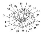
以下、図1乃至図5を参照しながら本発明の電動圧縮機保護装置について説明する。図1は本発明の電動圧縮機保護装置1の平面図であり、図2はその正面図である。さらにこの電動圧縮機保護装置1に使用されるケースに接続端子を装着した状態を図3の斜視図と図4の正面図に示す。また図5はこのケースの平面図である。この電動圧縮機保護装置1は、モータプロテクタ2(以下、単にプロテクタと称する)とこれを保持するケース3とを有している。このプロテクタ2は金属製の耐圧密閉容器2Aを持ち、この密閉容器内部にバイメタルなどの熱応動素子を利用した接点機構を有している。プロテクタの密閉容器2Aには、これを貫通して導電端子ピン2Bがガラスなどの電気絶縁性材料で気密に絶縁固定されている。またケース3はエンジニアリングプラスチック等の電気絶縁材料で形成されており、接続端子であるリセプタクル端子4とタブ端子5が配置されている。リセプタクル端子4とタブ端子5はそれぞれ一方に所定の端子との装着部4Aまたは5Aを有し、他方には前記導電端子ピン2Bとの接続用のリブが形成された溶接部4Bまたは5Bを有している。
The electric compressor protection device of the present invention will be described below with reference to FIGS. FIG. 1 is a plan view of an electric
ケース3は左右対称に形成されており、図1の平面図において図示手前側にあたる上面にはプロテクタ2が配置されるプロテクタ収納部3Aと、この収納部に隣接して端子接続部3Bと、さらにこれらの端子接続部に隣接した端子収納部3Cが設けられている。端子接続部3Bはそれぞれの端子の配置位置を隔壁3Lによって2ヶ所に分離独立されており、さらにそれぞれの端子接続部3Bに隣接した端子収納部3C同士もこれを囲む隔壁である周縁部3Dによって互いに独立している。この2つの端子収納部3Cは左右対称に配置された同一形状の貫通孔とされており、両者は周縁部3Dによって収納される端子間の電気絶縁距離が充分に採れるようにされている。
The
この端子収納部は少なくとも2種類の端子形状に対応しており、この実施例においてはリセプタクルを収納してタブを挿入するものにも、タブを収納してリセプタクルを挿入するものにも対応しており、相互に入れ替えて使用できるようにされている。端子接続部3Bと端子収納部3Cとの間には隔壁である周縁部3D部分を所定の開口幅で切り欠いた挿通部3Eが設けられており、それぞれの挿通部3Eの両壁面上部にはその開口幅を広げることによって段差3Fが設けられている。
This terminal accommodating portion corresponds to at least two types of terminal shapes. In this embodiment, the terminal accommodating portion accommodates a receptacle accommodating a receptacle and inserting a tab, and accommodating a tab accommodating a receptacle. They can be used interchangeably. Between the
リセプタクル端子4やタブ端子5は、それぞれこの挿通部3Eをまたいで配置され、それぞれの装着部4Aまたは5Aを端子収納部3Cに収納している。本実施例においてリセプタクル端子4の形状は、装着部4Aをケース3の下方に向けて配置するために装着部4Aと溶接部4Bとの間に位置する連通部4Cを一旦上方向に立ち上げてから装着部4Aを下方向に向かせた形状としており、装着部4Aを端子収納部3Cに差込むようにしてケースに取りつけられる。ここでリセプタクル端子4の連通部4Cの幅は挿通部3Eの下部の開口幅よりも広く、段差3F上の開口幅に合わせられている。こうしたことによりリセプタクル端子4の装着時に連通部4Cが挿通部の段差3Fに当接して挿入量を決められる。またリセプタクル端子4はその装着部4A側と溶接部4B側とで挿通部3Eを両側から弾性的に挟むようにして装着されており、装着部4Aが端子収納部3Cに設けられた返り止め3Gを弾性的に乗り越え、端面が係止されることによって脱落しないように保持固定されている。なお、本実施例では返り止め3Gを端子収納部3C側に設けた例を示したが、端子接続部23B側に設けてもよいことは言うまでもない。
The
また他方の端子収納部3Cに配置されるタブ端子5は、端子収納部から装着部5Aを上方に向けて配置される。タブ端子の連通部5Cの幅はケースの挿通部3Eの下部の開口幅に合わせ且つ、連通部5Cを溶接部5Bと同じ高さとされている。そのためタブ端子5を端子収納部3Cに配置した時に連通部5Cは段差3F上に留まること無く挿通部3Eの下端まで挿入されるので、タブ端子部分の先端を上方向に向けて配置した場合にもその先端高さを抑えることができ、タブを覆う周縁部3Dの高さを抑える事ができる。また中間部を何度も曲げる必要がないので端子の奥行きも抑えられ、端子収納部3Cを特に広げずに済む。またタブ端子は連通部5Cの側面が挿通部3Eに当たることで左右への動きを規制されるとともに、連通部5Cの前後の幅を太くすることで挿通部3Eの前後に当たるようにして前後への動きを規制している。こうしてタブ端子5は図1の手前側方向を除く5方向に対して拘束される。また手前側への力に対してはプロテクタとともに保持されるがこの点については後述する。
Further, the
ケース3のプロテクタ収納部3Aにはその側面にプロテクタ2の容器外周形状に沿ってせりあがる側壁3Hが設けられており、さらに両側からプロテクタの容器を抱え込むような形でせり出した保持部3Jが設けられている。側壁3Hの内側にはプロテクタの位置決め用の当接部3Mが設けられている。このプロテクタ収納部3Aに図1における図示下方からプロテクタ2を差込むように装着することによって、プロテクタはケースに対して所定の姿勢とされ、プロテクタの密閉容器2Aを隔壁3Lの端面、及び当接部3Mに当接することで位置決めされる。この状態でプロテクタの2本の導電端子ピン2Bは、それぞれリセプタクル端子とタブ端子の溶接部4Bまたは5B上に配置される。
The
ケース3の端子接続部3Bには各接続端子の溶接部4B、5Bと対向する位置に溶接作業用の貫通孔3Kが設けられている。導電端子ピン2Bと各端子の溶接部との溶接作業時には、導電端子ピン側から一方の溶接電極を当てると同時にこの貫通孔3Kを通して各端子の溶接部に他方の溶接電極を当てることによって溶接作業を可能にする。ケースに固定されている溶接部4B、5Bに対してこのようにプロテクタ2の導電端子ピン2Bを溶接することによって、プロテクタ2はケース3に対して保持固定される。近接する溶接部4B−5B間は前述したように隔壁3Lによって分離されるとともに充分な電気絶縁距離とされている。
The
ケース3の一方の端子収納部3Cに収納されたリセプタクル端子4には、接続部4Aに電動圧縮機の密閉容器に気密に固定された密閉端子のピンが挿入接続される。こうしてリセプタクル端子4は密閉端子に対して電気的に接続固定されるとともに、電動圧縮機保護装置1が密閉端子上に保持固定される。一方、タブ端子5はその接続部5Aをもう一方の端子収納部3Cに収納されており、電動機の巻線またはこの巻線に接続されたリード線が端子を介してこの接続部5Aに接続される。
In the
リセプタクル端子4とタブ端子5はそれぞれの接続部4A及び5Aをケース3の端子収納部3Cに収納することによって、それぞれの端子の先端部分である装着部は隔壁となる周縁部3Dに囲まれる。そのため製造時や取扱い時における外部応力はケースによって受けとめられ、接続端子は変形や破壊から確実に保護される。またタブ端子5は図1の手前方向については保持されていないが、ケースに保持部3Jを設けたことによってプロテクタ容器自体が保持されるので、前述したように連通部5Cにおける拘束構造と合わることで脱落することはない。なお本実施例においてはリセプタクル端子4とタブ端子5の突出量に合わせて両者を囲むケース3の周縁部3Dの上下方向に対する厚さをプロテクタ収納部3Aなどよりも厚くしているが、例えばタブ端子やリセプタクル端子の突出量を減らすことによって周縁部3Dの厚さも減らすことができることは言うまでもない。
The
本発明によれば、ケース3に対してリセプタクル端子4とタブ端子5を配置する際に、段差3Fを設けられた挿通部3Eを通して配置することによって端子それぞれの幅に応じて別の形態で保持することができる。また、ケースを左右対称にして挿通部及び端子収納部の形状を同じにし、さらに端子収納部はタブ端子とリセプタクル端子のどちらにも対応できるようにしたことで端子の組合せを変える場合には左右に対応した端子だけを用意すればよく、ケースそのものの種類を増やす必要が無くなる。なお、この実施例では端子接続部3B及び端子収納部3Cをそれぞれ隔壁3L及び周縁部3Dによって接続端子毎に独立させたているが、接続端子間に充分な電気絶縁距離が得られるのであればこれらの隔壁は必ずしも必要とされるものではなく、その場合は例えば端子収納部を一体化することもできる。
According to the present invention, when the
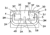
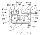
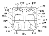
次に本発明の他の実施例について図6〜10を参照しながら説明する。図6は本発明の電動圧縮機用保護装置21の平面図であり、図7はそのケースの平面図、図8は図7のケースに端子を取付けた状態を示す斜視図である。また図9はプロテクタの取付状態を示す図6のA−A断面図及びB−B断面図、図10は保護装置を対象機器に接続した状態を説明するための平面図である。本実施例のケース23は前述の例と同様にエンジニアリングプラスチック等の電気絶縁材料で形成されており、接続端子であるリセプタクル端子24とタブ端子25が配意されている。リセプタクル端子24とタブ端子25はそれぞれ一方に所定の端子との装着部24Aまたは25Aを有し、他方にはプロテクタ2の導電端子ピン2Bとの接続用のリブが形成された溶接部24Bまたは25Bを有している。本実施例ではこの溶接部24B、25Bをそれぞれの端子の中心線に対して対称に配置することで、それぞれの端子が左右対称な形状とされている。
Next, another embodiment of the present invention will be described with reference to FIGS. 6 is a plan view of the
ケース23は左右対称に形成されており、平面図において手前側にプロテクタ2が配置されるプロテクタ収納部23Aと、この収納部に隣接して2ヶ所の端子接続部23Bと、さらにこれらの端子接続部に隣接した端子収納部23Cが設けられている。端子接続部23Bは隔壁23Lによって互いに独立しており、それぞれの端子接続部23Bに隣接した端子収納部23C同士もこれを囲む隔壁である周縁部23Dによって互いに独立している。この2つの端子収納部23Cはケース23の中心に対して左右対称に配置された同一形状の貫通孔とされており、両者は周縁部23Dによって収納される端子間の電気絶縁距離が充分に採れるようにされている。
The
この端子収納部23Cも前述の例と同様に少なくとも2種類の端子形状に対応している。この実施例においてはリセプタクルを収納してタブを挿入するものにも、タブを収納してリセプタクルを挿入するものにも対応しており、相互に入れ替えて使用できるようにされている。端子接続部23Bと端子収納部23Cとの間には隔壁である周縁部23D部分を所定の開口幅で切り欠いた挿通部23Eが設けられているが、本実施例においては前述の実施例1のようには深く切り欠かれることなく、端子の板厚程度の深さとされている。
This terminal
リセプタクル端子24やタブ端子25は、それぞれこの挿通部23Eをまたいで配置され、それぞれの装着部24Aまたは25Aを端子収納部23Cに収納している。本実施例においてはリセプタクル端子24の形状は、前述の例と同様に連通部24Cを一旦上方向に立ち上げてから装着部24Aを下方向に向かせた形状としており、装着部24Aを端子収納部23Cに差込むようにしてケースに取りつけられる。
The
端子収納部23Cは図9に示すように上部を広く、下部を狭くされており、下部はリセプタクル収納部23Fとして図6やそのA−A断面図である図9(A)に示すようにリセプタクル端子の装着部24Aの少なくとも先端が収納保持される形状とされている。そのためリセプタクル端子24を対象機器のタブ端子などに装着する際にケース23が装着部24Aの横方向へ動くのを規制している。リセプタクル端子24はその装着部24A側と溶接部24B側とでケースの挿通部23Eを両側から弾性的に挟むようにして装着されており、端子収納部23Cに設けられた返り止め23Gに装着部24Aの端面がかかることによって脱落しないように保持固定されている。なお端子収納部23C側に設けた返り止め23Gは前述の例と同様に端子接続部23B側に設けることができるが、この点は後述するタブ端子などにおいても同様であることは言うまでもない。
As shown in FIG. 9, the
また本実施例において他方の端子収納部23Cに配置されているタブ端子25は、図6やそのB−B断面図である図9(B)に示すように、リセプタクル端子24と同様に連通部25Cがケースの挿通部23Eをまたぐような形状に曲げられており、さらに一旦下方向に向けた装着部25Aの先端は上方向に曲げられている。このタブ端子25もリセプタクル端子と同様に挿通部23Eに対して弾性的に装着されており、装着部側に設けられた幅広部25Dが返り止め23Gに当たることで脱落が防止されている。またタブ端子25にリセプタクル端子を装着されたときにリセプタクル端子が端子収納部23Cに干渉しないように、タブ端子の装着部25Aは端子収納部23Cの上部の広い部分に収納される。
Further, in this embodiment, the
ケース23のプロテクタ収納部23Aの側面には前述の例と同様に側壁23Hが設けられており、また収納部23A内側にはプロテクタ2の容器を側面で支えて傾きを抑える当接部23Jが設けられている。さらに側壁23Hの内側にはプロテクタの端面が当たる位置決め用の当接部23Mが設けられている。プロテクタ収納部23Aと側壁23Hの内側の形状はプロテクタ容器の外周部にほぼ沿った形状とされている。このプロテクタ収納部23Aにプロテクタ2を装着することによって、プロテクタはケースに対して所定の姿勢とされ、プロテクタの密閉容器を当接部23Jと隔壁23Lの端面、及び当接部23Mに当接することで位置決めされる。この状態でプロテクタの2本の導電端子ピン2Bは、それぞれリセプタクル端子とタブ端子の溶接部24Bまたは25B上に配置される。
The
ケース23の端子接続部23Bには溶接作業用の貫通孔23Kが設けられており、この貫通孔23Kを通して各溶接部に溶接電極を当てることによって溶接作業を可能にする。このようにケースに固定された各端子にプロテクタ2の導電端子ピン2Bを溶接することによって、プロテクタ2はケース23に対して保持固定される。
The
本実施例では図10に示すように、ケース23の一方の端子収納部23Cに収納されたリセプタクル端子24の接続部24Aには、電動圧縮機の密閉容器に気密に固定された密閉端子のピン31に固定されたタブ端子32が図の向こう側から手前方向に向けて挿入されて接続保持される。こうしてリセプタクル端子24は密閉端子に対して電気的に接続固定されるとともに、電動圧縮機保護装置21は密閉端子上に保持固定される。一方、もう一方の端子収納部23Cに収納されたタブ端子25の接続部25Aには、電動機の巻線またはこの巻線に接続されたリード線がリセプタクル端子33を介して接続される。このリセプタクル端子33は図示手前から挿入されており、接続部の曲げ部分または端子収納部23Cの段差に当たることで挿入量が決められる。また端子収納部23Cの上部は下部のリセプタクル収納部23Fよりも広くされており、タブ端子25の曲げ成型された接続部25Aにリセプタクル端子33を取付けることができる。さらに端子収納部23Cの内面がリセプタクル端子33の周縁部に沿うようにすることで、端子の動きを抑えて振動などに対する保持力を高めることができる。
In this embodiment, as shown in FIG. 10, the connecting
なお、本実施例においてリセプタクル端子24とタブ端子25はどちらも溶接部を含めてそれぞれ左右対称な形状とされており、さらにケースへの装着方法も同じにされている。そのためケース23に対してどちらの端子収納部23Cに装着することも可能である。例えば図6におけるリセプタクルとタブの位置関係を入れ替えることはもちろん、必要であれば双方に同一の端子を使用することも可能になる。この実施例によれば端子の入替えを必要とする場合であっても、ケースはもちろん端子も左右別々に用意する必要はないので、新たな部品を作成することなく仕様変更に対応することができる。
In the present embodiment, the
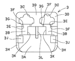
上述した各実施例においてはタブ端子の形状は貫通孔である端子収納部に制限されるため、横方向に引出すことは難しい。そこで次に本発明の第3の実施例として端子形状の自由度を上げた例について、図11乃至図13を参照して説明する。図11はこの電動圧縮機保護装置41の平面図であり、前述の例と同様の部品には同じ記号を付して詳細な説明は省略する。また図12はプロテクタの取付状態を示す図11のC−C断面図及びD−D断面図、図13はケースに端子を取付けた状態を示す斜視図である。この電動圧縮機保護装置41は前述の例と同じプロテクタ2が使用されている。このプロテクタ2は電気絶縁材料で形成されたケース43上に保持固定されている。ケースのプロテクタ収納部43Aに配置されたプロテクタ2は、その容器を保持部43Jで保持されるとともに、導電端子ピン2Bを接続端子であるタブ端子44やリセプタクル端子24に溶接することでケース上に固定される。このケース43は接続端子の左右入れ替えなどが可能な構造とされており、そのため左右対称な構造となっている。
In each of the above-described embodiments, the shape of the tab terminal is limited to the terminal accommodating portion that is a through hole, so that it is difficult to pull it out in the lateral direction. Accordingly, an example in which the degree of freedom of the terminal shape is increased as a third embodiment of the present invention will be described with reference to FIGS. FIG. 11 is a plan view of the electric
ケース43のプロテクタ収納部43Aとそれに隣接した端子接続部43Bの形状は実施例1で示したケースとほぼ同じであり、隔壁43Lで分割された2つの端子接続部43Bにはそれぞれに溶接電極を挿通するための貫通孔43Kが設けられている。これに対して端子収納部側の形状は前述のものと異なっており、リセプタクル端子24の接続部を収納するために貫通孔になっている端子収納部43Cの周縁部43Mのうち、ケース外側部分の二辺を高さ方向に大きく削られている点で異なっている。周縁部のその他の部分は前述の例と同じような高さのまま周縁隔壁部43Dとされて、隣接する端子収納部同士、あるいは端子収納部と端子接続部の間の隔壁として機能する。この隔壁部43Dには接続端子であるリセプタクル端子24やタブ端子44を通す挿通部43Eが所定の開口幅で設けられている。また挿通部43Eの上部には前述の例と同様に開口幅を広げた段部43Fが設けられている。本実施例における二つの端子収納部43Cは隔壁などの位置関係が異なっているが、後述するタブ端子の引き出し方向の関係で左右対象に配置されているだけで実質的に同一形状とされている。
The shape of the
端子収納部43Cは貫通孔とされており、リセプタクル端子24は図12(B)に示すように端子収納部に装着部24Aを挿入されている。またリセプタクル端子は連通部24Cが挿通部の段差43Fに当接することによって挿入量が決められる。また装着部24A側と溶接部24B側とでケースの挿通部43Eを両側から弾性的に挟むようにすると同時に、装着部24Aの端面が返り止め43Gに当接することでケース43に対して脱落しないように固定されている。
The terminal
本実施例のタブ端子44は図12(A)などに示すように装着部44Aから溶接部44Cまでほぼ同一平面とされ、連通部44Bは挿通部43Eの下部の幅より狭くされることにより、挿通部43Eの底部に当接する。こうしてタブ端子44はケース43の端子収納部43Cの上表面に沿って配置される。
As shown in FIG. 12A and the like, the
本実施例においてはこのように端子収納部43Cの周縁部43Mの端面をその一部が挿通部の底部と同じ高さにまで切り欠かれていることにより、タブ端子の装着部をケースに対して横方向に引き出すことができる。このタブ端子の装着部の引出し方向は図に示した方向のみに限定されるものでは無く、例えば真っ直ぐ伸ばすことで図11における上方向へ引出すようにしてもよいし、前述の例のように端子収納部から垂直方向へ曲げたものとしてもよい。なお、タブ端子44は挿通部43Eに単に上方向から装着したものを示しているが、たとえばこの挿通部に切り欠きや突起などを設けてタブ端子をそこにかみ合わせてからプロテクタ2と溶接することで、タブ端子とプロテクタの溶接部にかかる負担を分散することができる。
In the present embodiment, the end surface of the
この実施例においてリセプタクル端子24は、前述の第2の実施例と同様に溶接部24Bを左右に広げて端子全体を左右対称するとともに、溶接部24Bのどちらの端でも溶接可能にされている。この構造によればリセプタクル端子24はケース43に対して左右どちらの端子収納部43Cに配置する場合にも溶接固定が可能になるので、リセプタクル端子の位置の入れ替えが必要な時にも同一のリセプタクル端子が使用でき、部品の共通化を図ることができる。また例えばタブ端子においても横方向への曲げなどのない対称な構造とされる場合には、溶接部を同様の構造として共有化を図ることができる。
In this embodiment, the
なお、本実施例ではタブ端子の形状の自由度を大きくするために端子収納部の周縁部の高さを二辺に亘って削ったものを例に説明したが、例えばタブ端子の引出し方向が特定方向に限られているのであればタブ端子とリセプタクル端子との互換性だけを考慮した端子接続部と端子収納部の直線上の一辺のみを削除した構造であってもよい。またタブ端子の保持方法は実施例のものに限定するものではなく、リセプタクル端子や前述の第2の実施例のようにケースの挿通部43Eに弾性的に装着する構造としてもよい。
In this embodiment, the example in which the height of the peripheral portion of the terminal storage portion is cut across two sides in order to increase the degree of freedom of the shape of the tab terminal has been described. If the direction is limited to a specific direction, a structure in which only one side on the straight line of the terminal connection portion and the terminal storage portion considering only the compatibility between the tab terminal and the receptacle terminal may be deleted. The tab terminal holding method is not limited to that of the embodiment, and may be a structure that is elastically attached to the receptacle terminal or the
前述の各実施例では端子収納部をケースに対して実質的に左右対象に配置したものを例に説明したが、それぞれの端子先端形状の入れ替えに対応可能であれば例えば図14に示す電動圧縮機保護装置61のようにケース63の端子収納部63A及び63Bの位置関係をずらしてもよい。この実施例においては一方の接続端子は前述の実施例1と同様のリセプタクル端子4とし、他方の接続端子65は先端形状をタブ端子としているが、互いの先端形状を入れ替えることができることについては前述の例と同様である。このリセプタクル端子4は前述の実施例と同様に連接部4Cでケースの一方の挿通部63Cを越えるように弾性的に装着固定されている。またタブ端子65Aの連接部65Aは溶接部65Bと同一平面であり、他方の挿通部63Dの底部に当接する。その他の点については端子収納部の位置関係が違うことと接続端子の連接部の長さが違うこと以外は同様であるので詳細な説明は省略する。
In each of the above-described embodiments, the case where the terminal storage portion is arranged substantially in the left and right direction with respect to the case has been described as an example. However, if it is possible to replace each terminal tip shape, for example, electric compression shown in FIG. Like the
さらに前述の各実施例では特に板厚の薄いリセプタクル端子について外部からの応力による変形を防ぐために端子収納部を隔壁で囲み貫通孔としたものを中心に説明したが、必ずしも貫通孔にする必要はなく、例えば図15に示す電動圧縮機保護装置71のように接続端子の先端を隔壁で挟み込むように保持するものであってもよい。この電動圧縮機保護装置71のケース73は端子収納部73Aが隔壁で端子先端部の全周を覆う貫通孔形状ではなく、リセプタクル端子4の先端を隔壁の内面で挟み込むようにされているとともに隔壁の一面73Bがタブ端子の幅に合わせて開口されることで、タブ端子75が横方向に挿通可能にされている。本実施例によれば端子収納部を貫通孔としなくてもリセプタクル端子への外力の影響を隔壁によって受けることができるとともに、タブ端子もケースの挿通部73Cと開口部73Bとで保持されることにより特に横方向の力に対して強固に保持される。
Further, in each of the above-described embodiments, the receptacle terminal having a thin plate thickness has been described mainly with the terminal housing portion surrounded by a partition wall to prevent deformation due to external stress. However, the through hole is not necessarily required. Instead, for example, an electric
上述の各実施例においては二つの端子収納部において、それぞれに収納される端子先端形状を入れ替え可能なものについて説明したが、それぞれの端子収納部を少なくとも2種類の接続端子形状に対応させることもできる。例えば端子収納部のうち一方だけをタブ端子を横に引き出す構造としたい場合には、一方の端子収納部を実施例1の形状として他方を実施例3の形状とすればよい。このようにそれぞれの端子収納部が複数の端子先端形状に対応することで、ケースの形状を変えなくても対応する接続端子を用意することで保護装置の取付方法の自由度を増すことができる。 In each of the above-described embodiments, the two terminal storage portions have been described in which the terminal tip shapes stored in the respective terminal storage portions can be interchanged. However, each terminal storage portion may correspond to at least two types of connection terminal shapes. it can. For example, when it is desired to have a structure in which only one of the terminal storage portions pulls out the tab terminal horizontally, one terminal storage portion may have the shape of the first embodiment and the other has the shape of the third embodiment. In this way, each terminal accommodating portion corresponds to a plurality of terminal tip shapes, so that the degree of freedom of the protective device mounting method can be increased by preparing a corresponding connection terminal without changing the shape of the case. .
以上述べたように、本発明の電動圧縮機用保護装置によれば、ケース上の2箇所の端子収納部は少なくとも互いに収納される接続端子先端形状を入れ替え可能にしたことによって、端子の入れ替えを行う場合にもケースはそのまま使用することができる。また接続端子をケースに一体整形するのではなく後から装着固定するようにしたことで、ケースの汎用性が向上し、製造がより容易になる。 As described above, according to the protection device for an electric compressor of the present invention, the terminal storage portions at two locations on the case can be replaced at least by connecting the tip shapes of the connection terminals stored in each other. The case can be used as it is. In addition, since the connection terminals are attached and fixed to the case instead of being integrally molded, the versatility of the case is improved, and the manufacture becomes easier.
またこの端子収納部を同一形状としたり、左右対象に配置することで接続端子の形状を両側の端子収納部に対応させることがより容易になる。さらにそれぞれの接続端子を左右対称な形状とすることで、接続端子も含めて部品のバリエーションを最小限にすることが可能になる。 Moreover, it becomes easier to make the shape of the connection terminal correspond to the terminal accommodating parts on both sides by making the terminal accommodating parts the same shape or arranging them on the left and right sides. Furthermore, by making each connection terminal symmetrical, it becomes possible to minimize variations of parts including the connection terminals.
端子収納部に貫通孔を設けてどちらの開口部からも接続端子に外部端子を装着可能にしたことで、保護装置の取付姿勢に関する自由度が向上し、より多くの保護対象機器への使用が可能になる。 By providing a through-hole in the terminal housing and making it possible to attach an external terminal to the connection terminal from either opening, the degree of freedom regarding the mounting orientation of the protective device is improved and it can be used for more protected devices. It becomes possible.
またケース上の挿通部の開口幅を部分的に変え、この挿通部を通す接続端子の幅を前記開口幅の所定位置に合わせることにより、接続端子のケース上での当接位置と姿勢を決めることができる。またケースに設けられた端子収納部の端面の一部を挿通部の底部と同じ高さにまで切り欠くことで、接続端子の形状の自由度を上げてより多様な装着方法に対応することができる。 Further, by changing the opening width of the insertion portion on the case partially, and adjusting the width of the connection terminal passing through the insertion portion to a predetermined position of the opening width, the contact position and posture of the connection terminal on the case are determined. be able to. In addition, by cutting out a part of the end surface of the terminal storage part provided in the case to the same height as the bottom part of the insertion part, it is possible to increase the degree of freedom of the shape of the connection terminal and cope with various mounting methods. it can.
またそれぞれの端子収納部を少なくとも2種類の端子形状に対応させることにより、接続端子の組合せを変えることで1種類のケースを複数の取付方法に対応させることができる。そのため取付方法ごとにケースの種類を増やす必要がなくなるので、部品の汎用性が広がり製造コストを低減させることができる。 Moreover, by making each terminal accommodating part correspond to at least two types of terminal shapes, one type of case can be made compatible with a plurality of attachment methods by changing the combination of connection terminals. For this reason, it is not necessary to increase the number of types of cases for each mounting method, so that the versatility of parts can be increased and the manufacturing cost can be reduced.
1、21、41、61、71:電動圧縮機保護装置
2:モータプロテクタ
3、23,43、63、73:ケース
3B、23B、43B:端子接続部
3C、23C、43C、63A、63B、73A:端子収納部
3E、23E、43E、63C、63D、73B:挿通部
3G、23G、43G:返り止め
3J、43J:保持部
4、24:リセプタクル端子
4A、24A:装着部
4B、24B:溶接部
4C、24C、44B:連通部
5、25、44:タブ端子
5A、25A:装着部
5B、25B:溶接部
5C、25C、44B、65A:連通部
23F:リセプタクル収納部
23J:当接部
25D:幅広部
1, 21, 41, 61, 71: Electric compressor protection device 2:
Claims (9)
前記ケースには接続端子が装着され、
この接続端子にモータプロテクタの端子を接続固定することによりモータプロテクタがケースに対して所定の姿勢で保持固定される電動圧縮機用保護装置において、
前記ケースはモータプロテクタ収納部と端子接続部、さらに2箇所の端子収納部を有しており、
端子接続部はモータプロテクタ収納部に対して隣接し、
さらに端子収納部は前記端子接続部と隔壁を挟んで隣接しており、
前記接続端子は端子接続部と端子収納部との間を跨いで装着固定されており、
端子収納部には接続端子の先端部が収納され、
端子接続部でモータプロテクタの導電端子が接続端子と接続固定され、
前記2箇所の端子収納部は少なくとも互いに収納される接続端子先端を入れ替え可能にされていることを特徴とする電動圧縮機用保護装置。 A motor protector having a contact mechanism in a metal sealed container and an electrically insulating case for holding the motor protector;
A connection terminal is attached to the case,
In the protective device for an electric compressor in which the motor protector is held and fixed in a predetermined posture with respect to the case by connecting and fixing the terminal of the motor protector to the connection terminal,
The case has a motor protector storage part and a terminal connection part, and further two terminal storage parts,
The terminal connection is adjacent to the motor protector storage,
Furthermore, the terminal storage part is adjacent to the terminal connection part across the partition,
The connection terminal is mounted and fixed across the terminal connection part and the terminal storage part,
The terminal storage part houses the tip of the connection terminal,
At the terminal connection, the motor protector's conductive terminal is connected and fixed to the connection terminal.
The protective device for an electric compressor, wherein the two terminal storage portions are configured so that at least the connection terminal tips stored in each other can be exchanged.
この挿通部はその一部の開口幅を変えられており、
接続端子の連通部分の幅を挿通部の任意の位置における開口幅に合わせることによって接続端子が挿通部の所望の位置で当接保持されることを特徴とする請求項1乃至5のいずれか1項に記載の電動圧縮機用保護装置。 Between the terminal storage part and the terminal connection part of the case, there is provided an insertion part in which a partition wall is cut out with a predetermined opening width,
This insertion part has a part of its opening width changed,
The connection terminal is held in contact with a desired position of the insertion portion by matching the width of the communication portion of the connection terminal with the opening width at an arbitrary position of the insertion portion. The protective device for an electric compressor according to Item.
前記ケースには接続端子が装着され、
この接続端子にモータプロテクタの端子を接続固定することによりモータプロテクタがケースに対して所定の姿勢で保持固定される電動圧縮機用保護装置において、
前記ケースはモータプロテクタ収納部を1箇所と端子接続部を2箇所、さらに端子収納部を2箇所有しており、
2箇所の端子接続部はモータプロテクタ収納部に対してそれぞれ隣接するとともに端子接続部同士は互いに隔壁によって独立し、
さらに2箇所の端子収納部は実質的に同一形状とされ、
それぞれの端子収納部は前記端子接続部の一方と隔壁を挟んで隣接するとともに端子収納部同士は互いに隔壁によって独立しており、
端子接続部及び端子収納部は各々ケースに対して実質的に左右対称に配置されており、
それぞれの隣接した端子接続部と端子収納部との間には前記接続端子が両者を跨いで装着固定され、
端子接続部でモータプロテクタの導電端子が接続端子と接続固定され、
端子収納部はそれぞれ少なくとも2種類の接続端子形状に対応していることを特徴とする電動圧縮機用保護装置。
A motor protector having a contact mechanism in a metal sealed container and an electrically insulating case for holding the motor protector;
A connection terminal is attached to the case,
In the protective device for an electric compressor in which the motor protector is held and fixed in a predetermined posture with respect to the case by connecting and fixing the terminal of the motor protector to the connection terminal,
The case has one motor protector storage part, two terminal connection parts, and two terminal storage parts,
The two terminal connection portions are adjacent to the motor protector storage portion and the terminal connection portions are independent from each other by a partition wall.
Further, the two terminal storage portions have substantially the same shape,
Each terminal storage part is adjacent to one of the terminal connection parts across the partition wall, and the terminal storage parts are independent from each other by the partition wall,
The terminal connection part and the terminal storage part are respectively arranged substantially symmetrically with respect to the case,
Between each adjacent terminal connection part and the terminal storage part, the connection terminal is mounted and fixed across both,
At the terminal connection, the motor protector's conductive terminal is connected and fixed to the connection terminal.
Each of the terminal storage portions corresponds to at least two types of connection terminal shapes.
Priority Applications (2)
| Application Number | Priority Date | Filing Date | Title |
|---|---|---|---|
| JP2004110038A JP4522132B2 (en) | 2004-04-02 | 2004-04-02 | Protection device for electric compressor |
| CNB2004100978735A CN100532838C (en) | 2004-04-02 | 2004-11-30 | Protection device for electric compressor |
Applications Claiming Priority (1)
| Application Number | Priority Date | Filing Date | Title |
|---|---|---|---|
| JP2004110038A JP4522132B2 (en) | 2004-04-02 | 2004-04-02 | Protection device for electric compressor |
Publications (2)
| Publication Number | Publication Date |
|---|---|
| JP2005291154A true JP2005291154A (en) | 2005-10-20 |
| JP4522132B2 JP4522132B2 (en) | 2010-08-11 |
Family
ID=35049619
Family Applications (1)
| Application Number | Title | Priority Date | Filing Date |
|---|---|---|---|
| JP2004110038A Expired - Lifetime JP4522132B2 (en) | 2004-04-02 | 2004-04-02 | Protection device for electric compressor |
Country Status (2)
| Country | Link |
|---|---|
| JP (1) | JP4522132B2 (en) |
| CN (1) | CN100532838C (en) |
Cited By (4)
| Publication number | Priority date | Publication date | Assignee | Title |
|---|---|---|---|---|
| CN101938113B (en) * | 2009-06-29 | 2013-06-05 | 上海电器股份有限公司人民电器厂 | Mounting groove structure of display operation module of motor protector |
| KR101412362B1 (en) | 2007-01-26 | 2014-06-25 | 센사타 테크놀로지스 매사추세츠, 인크. | Motor protector attachment system |
| JP2018170839A (en) * | 2017-03-29 | 2018-11-01 | Ntn株式会社 | Electric actuator and manufacturing method for electric actuator |
| WO2023084736A1 (en) * | 2021-11-12 | 2023-05-19 | 株式会社生方製作所 | Device for attaching motor protector, and encapsulated-type electric compressor |
Citations (4)
| Publication number | Priority date | Publication date | Assignee | Title |
|---|---|---|---|---|
| JPH07241061A (en) * | 1994-02-25 | 1995-09-12 | Ubukata Seisakusho:Kk | Protector for enclosed motor compressor |
| JPH10112357A (en) * | 1996-10-08 | 1998-04-28 | Sumitomo Wiring Syst Ltd | Connector |
| JP2000180266A (en) * | 1998-12-16 | 2000-06-30 | Ubukata Seisakusho:Kk | Heat sensitive sensor and hermetic motor-driven compressor fitted therewith |
| JP2002352893A (en) * | 2001-05-25 | 2002-12-06 | Yazaki Corp | connector |
Family Cites Families (2)
| Publication number | Priority date | Publication date | Assignee | Title |
|---|---|---|---|---|
| US5515217A (en) * | 1993-09-22 | 1996-05-07 | Ubukata Industries Co., Ltd. | Thermal protector for hermetic electrically-driven compressors |
| CN1154212C (en) * | 2001-09-18 | 2004-06-16 | 钱根良 | Electric connector |
-
2004
- 2004-04-02 JP JP2004110038A patent/JP4522132B2/en not_active Expired - Lifetime
- 2004-11-30 CN CNB2004100978735A patent/CN100532838C/en not_active Expired - Lifetime
Patent Citations (4)
| Publication number | Priority date | Publication date | Assignee | Title |
|---|---|---|---|---|
| JPH07241061A (en) * | 1994-02-25 | 1995-09-12 | Ubukata Seisakusho:Kk | Protector for enclosed motor compressor |
| JPH10112357A (en) * | 1996-10-08 | 1998-04-28 | Sumitomo Wiring Syst Ltd | Connector |
| JP2000180266A (en) * | 1998-12-16 | 2000-06-30 | Ubukata Seisakusho:Kk | Heat sensitive sensor and hermetic motor-driven compressor fitted therewith |
| JP2002352893A (en) * | 2001-05-25 | 2002-12-06 | Yazaki Corp | connector |
Cited By (6)
| Publication number | Priority date | Publication date | Assignee | Title |
|---|---|---|---|---|
| KR101412362B1 (en) | 2007-01-26 | 2014-06-25 | 센사타 테크놀로지스 매사추세츠, 인크. | Motor protector attachment system |
| CN101938113B (en) * | 2009-06-29 | 2013-06-05 | 上海电器股份有限公司人民电器厂 | Mounting groove structure of display operation module of motor protector |
| JP2018170839A (en) * | 2017-03-29 | 2018-11-01 | Ntn株式会社 | Electric actuator and manufacturing method for electric actuator |
| JP7146369B2 (en) | 2017-03-29 | 2022-10-04 | Ntn株式会社 | Electric actuator and method for manufacturing electric actuator |
| WO2023084736A1 (en) * | 2021-11-12 | 2023-05-19 | 株式会社生方製作所 | Device for attaching motor protector, and encapsulated-type electric compressor |
| US12170471B2 (en) | 2021-11-12 | 2024-12-17 | Ubukata Industries Co., Ltd. | Device for attaching motor protector and encapsulated-type electric compressor |
Also Published As
| Publication number | Publication date |
|---|---|
| JP4522132B2 (en) | 2010-08-11 |
| CN1676930A (en) | 2005-10-05 |
| CN100532838C (en) | 2009-08-26 |
Similar Documents
| Publication | Publication Date | Title |
|---|---|---|
| US5615071A (en) | Thermal protector for hermetic electrically-driven compressors | |
| US5515217A (en) | Thermal protector for hermetic electrically-driven compressors | |
| US20030076213A1 (en) | Fuse | |
| US6726506B2 (en) | Fuse holder | |
| JP5941515B2 (en) | connector | |
| EP1235245B1 (en) | Fuse holder | |
| US6666723B2 (en) | Multiple-fuse holder | |
| JP2021045019A (en) | Electrical junction box | |
| JP4522132B2 (en) | Protection device for electric compressor | |
| CN120188250A (en) | Plug-in fuse and method for manufacturing the same | |
| JP4382493B2 (en) | Thermally responsive switch | |
| JP4706613B2 (en) | Slow blow fuse fuse element, slow blow fuse and electrical junction box | |
| JP2020202042A (en) | Movable connector | |
| JP2009110856A (en) | Support structure of fusible link unit | |
| JP2020080587A (en) | Bus bar assembly structure, electrical connection box, and wire harness | |
| JP4982142B2 (en) | Overload relay holding device for electric compressor | |
| JP4011397B2 (en) | Internal protector for hermetic electric compressor | |
| JP3916037B2 (en) | Sealed electric compressor protector | |
| JP3853779B2 (en) | Internal protector for hermetic electric compressor | |
| JPH07241061A (en) | Protector for enclosed motor compressor | |
| CN100593890C (en) | Fuse cavity structure and electric connection box | |
| US20060205248A1 (en) | Voltmeter relay with shaped base which contains slots designed to form seatings for the insertion of "faston" connectors | |
| JP3010141B2 (en) | Protector for hermetic electric compressor | |
| JP4207821B2 (en) | Electrical junction box | |
| JP6457817B2 (en) | Electronic component unit and electrical junction box |
Legal Events
| Date | Code | Title | Description |
|---|---|---|---|
| A621 | Written request for application examination |
Free format text: JAPANESE INTERMEDIATE CODE: A621 Effective date: 20070330 |
|
| A977 | Report on retrieval |
Free format text: JAPANESE INTERMEDIATE CODE: A971007 Effective date: 20090820 |
|
| A131 | Notification of reasons for refusal |
Free format text: JAPANESE INTERMEDIATE CODE: A131 Effective date: 20090915 |
|
| A521 | Request for written amendment filed |
Free format text: JAPANESE INTERMEDIATE CODE: A523 Effective date: 20091116 |
|
| TRDD | Decision of grant or rejection written | ||
| A01 | Written decision to grant a patent or to grant a registration (utility model) |
Free format text: JAPANESE INTERMEDIATE CODE: A01 Effective date: 20100427 |
|
| A01 | Written decision to grant a patent or to grant a registration (utility model) |
Free format text: JAPANESE INTERMEDIATE CODE: A01 |
|
| A61 | First payment of annual fees (during grant procedure) |
Free format text: JAPANESE INTERMEDIATE CODE: A61 Effective date: 20100525 |
|
| R150 | Certificate of patent or registration of utility model |
Ref document number: 4522132 Country of ref document: JP Free format text: JAPANESE INTERMEDIATE CODE: R150 Free format text: JAPANESE INTERMEDIATE CODE: R150 |
|
| FPAY | Renewal fee payment (event date is renewal date of database) |
Free format text: PAYMENT UNTIL: 20130604 Year of fee payment: 3 |
|
| R250 | Receipt of annual fees |
Free format text: JAPANESE INTERMEDIATE CODE: R250 |
|
| R250 | Receipt of annual fees |
Free format text: JAPANESE INTERMEDIATE CODE: R250 |
|
| R250 | Receipt of annual fees |
Free format text: JAPANESE INTERMEDIATE CODE: R250 |
|
| R250 | Receipt of annual fees |
Free format text: JAPANESE INTERMEDIATE CODE: R250 |
|
| R250 | Receipt of annual fees |
Free format text: JAPANESE INTERMEDIATE CODE: R250 |
|
| R250 | Receipt of annual fees |
Free format text: JAPANESE INTERMEDIATE CODE: R250 |
|
| R250 | Receipt of annual fees |
Free format text: JAPANESE INTERMEDIATE CODE: R250 |
|
| R250 | Receipt of annual fees |
Free format text: JAPANESE INTERMEDIATE CODE: R250 |
|
| R250 | Receipt of annual fees |
Free format text: JAPANESE INTERMEDIATE CODE: R250 |
|
| R250 | Receipt of annual fees |
Free format text: JAPANESE INTERMEDIATE CODE: R250 |
|
| R250 | Receipt of annual fees |
Free format text: JAPANESE INTERMEDIATE CODE: R250 |
|
| EXPY | Cancellation because of completion of term |