JP2005291129A - Butterfly valve - Google Patents
Butterfly valve Download PDFInfo
- Publication number
- JP2005291129A JP2005291129A JP2004108939A JP2004108939A JP2005291129A JP 2005291129 A JP2005291129 A JP 2005291129A JP 2004108939 A JP2004108939 A JP 2004108939A JP 2004108939 A JP2004108939 A JP 2004108939A JP 2005291129 A JP2005291129 A JP 2005291129A
- Authority
- JP
- Japan
- Prior art keywords
- bearing
- hole
- annular seal
- housing
- valve
- Prior art date
- Legal status (The legal status is an assumption and is not a legal conclusion. Google has not performed a legal analysis and makes no representation as to the accuracy of the status listed.)
- Pending
Links
Images


Landscapes
- Control Of Throttle Valves Provided In The Intake System Or In The Exhaust System (AREA)
- Lift Valve (AREA)
- Details Of Valves (AREA)
Abstract
【課題】 従来と比較して良好なシール性を備えたバタフライ弁1を提供する。
【解決手段】 ハウジング2の半径方向の貫通孔2Bに軸受4を圧入して嵌着し、コイルばね7によってシール手段6を軸受4に向けて付勢する。
シール手段6は、コイルばね7を当接させたプレート16と、その内方側の3枚の環状シール部材15とから構成している。上記コイルばね7の弾発力によって環状シール部材15は、プレート16と軸受4とにより強く挟持されている。
【選択図】 図2PROBLEM TO BE SOLVED: To provide a butterfly valve 1 having a better sealing property as compared with the conventional one.
A bearing 4 is press-fitted and fitted into a radial through hole 2B of a housing 2, and a seal means 6 is urged toward the bearing 4 by a coil spring 7.
The sealing means 6 is composed of a plate 16 with which the coil spring 7 is abutted and three annular seal members 15 on the inner side thereof. The annular seal member 15 is strongly held between the plate 16 and the bearing 4 by the elastic force of the coil spring 7.
[Selection] Figure 2
Description
本発明は例えば排気ブレーキ装置に用いて好適なバタフライ弁に関し、より詳しくは、その弁軸とハウジングの貫通孔との間のシールを維持するシール手段の改良に関する。 The present invention relates to a butterfly valve suitable for use in, for example, an exhaust brake device, and more particularly to an improvement in sealing means for maintaining a seal between the valve shaft and a through hole of a housing.
従来、排気ブレーキ装置に用いられるバタフライ弁として次のような構成を備えたものは知られている。すなわち、ガスが流通するガス通路およびこのガス通路と交差する方向に穿設した半径方向の貫通孔とを有するハウジングと、上記ハウジングのガス通路内に設けた弁体と、上記ハウジングの貫通孔に嵌合した軸受と、上記貫通孔および上記軸受に貫通されて該軸受によって回転自在に軸支されるとともに、内方側の端部を上記弁体に連結した弁軸と、上記軸受の隣接位置となる上記ハウジングの貫通孔内に配置されて上記弁軸と上記貫通孔との間のシールを維持するシール手段と備えたバタフライ弁は知られている(例えば特許文献1、特許文献2、特許文献3)。
従来一般に、排気ブレーキ装置に用いられるバタフライ弁は排気ガスの熱によって高温となるので、焼き付き防止のために軸受の外周面とハウジングの貫通孔との間、および軸受と弁軸との間には僅かに維持するようにしている。
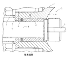
そこで、図3に示すように、上記特許文献1におけるシール手段6は大小2組の環状シール部材から構成してあり、それら大小2組の環状シール部材を軸受4の外方側の端面とブラケット8との間に配置している。そして、排気ガスの圧力によって弁体3およびそれに連結した弁軸5が外方へ付勢されると、上記軸受4が貫通孔2Bで外方側へ僅かに移動して、該軸受4の外方側の端面と上記ブラケット8との間で大小2組の環状シール部材が強く挟持されるようになっていたものである。小さい環状シール部材の内周面は弁軸5の外周面に密着し、大きい環状シール部材の外周面は、ハウジングの貫通孔2Bに密着し、かつブラケットと軸受4の外方側の端面とによって、上記環状シール部材が挟持されることにより、貫通孔2Bと弁軸5との間のシールを維持するように構成されていたものである。
さらに、特許文献2および特許文献3のシール手段においても、大小の1組以上の環状シール部材を備えて、これら環状シール部材を軸受の端面とブラケット等の固定部材との間で挟持することで、ハウジングの貫通孔と弁軸の外周面との間のシールを維持するようにしていたものである。
Conventionally, butterfly valves used in exhaust brake devices are heated to high temperatures due to the heat of exhaust gas. I try to keep it slightly.
Therefore, as shown in FIG. 3, the sealing means 6 in
Further, in the sealing means of
ところで、上述した従来のシール手段においては、弁軸および弁体が振動することに伴って、上記弁軸の外周面および環状シール部材の内周面が摩耗して、それらの間に微小な隙間が生じることになる。そして、その隙間から排気ガスが洩れてシール手段によるシール性が低下するという欠点が指摘されていたものである。
そこで、本発明の目的は、振動を受けても摩耗しにくくシール性が良好なバタフライ弁のシール手段を提供することである。
By the way, in the conventional sealing means described above, as the valve shaft and the valve body vibrate, the outer peripheral surface of the valve shaft and the inner peripheral surface of the annular seal member are worn, and a minute gap therebetween. Will occur. Further, it has been pointed out that the exhaust gas leaks from the gap and the sealing performance by the sealing means is lowered.
Accordingly, an object of the present invention is to provide a sealing means for a butterfly valve which is not easily worn even when subjected to vibrations and has a good sealing property.
すなわち、本発明は、ガスが流通するガス通路およびこのガス通路と交差する方向に穿設した半径方向の貫通孔とを有するハウジングと、上記ハウジングのガス通路内に設けた弁体と、上記ハウジングの貫通孔に嵌合した軸受と、上記貫通孔および上記軸受に貫通されて該軸受によって回転自在に軸支されるとともに、内方側の端部を上記弁体に連結した弁軸と、上記軸受の隣接位置となる上記ハウジングの貫通孔内に配置されて上記弁軸と上記貫通孔との間のシールを維持するシール手段と備えたバタフライ弁において、
上記軸受を上記ハウジングの貫通孔に圧入して上記貫通孔内に嵌着するとともに、上記シール手段は、弁軸を囲繞して配置されて内周部を弁軸に密着させた環状シール部材と、この環状シール部材の隣接外方位置に配置したプレートとを備え、上記プレートを上記軸受に向けて付勢するばねを設けて、該ばねの付勢力によって上記プレートと上記軸受の外方側の端面との間に上記環状シール部材を挟持したものである。
That is, the present invention includes a housing having a gas passage through which a gas flows and a radial through hole formed in a direction intersecting the gas passage, a valve body provided in the gas passage of the housing, and the housing A bearing fitted into the through-hole, a valve shaft that passes through the through-hole and the bearing and is rotatably supported by the bearing, and has an inner end connected to the valve body, and In the butterfly valve provided with sealing means arranged in the through hole of the housing that is adjacent to the bearing and maintaining a seal between the valve shaft and the through hole,
The bearing is press-fitted into the through-hole of the housing and fitted into the through-hole, and the sealing means is disposed around the valve shaft, and an annular seal member having an inner peripheral portion in close contact with the valve shaft; A plate disposed at an outer position adjacent to the annular seal member, and provided with a spring for urging the plate toward the bearing, and the urging force of the spring causes the plate and the bearing on the outer side. The annular seal member is sandwiched between the end surface.
このような構成によれば、ばねの付勢力により、プレートと軸受とによって環状シール部材が軸方向に挟持されるため、弁軸が振動しても環状シール部材は弁軸の半径方向に振動しにくくなる。そのため、環状シール部材の内周面およびそれが密着した弁軸の外周面が摩耗しにくい。これにより、環状シール部材の内周面と弁軸の外周面との間に隙間が生じることを抑制できるので、良好なシール性を維持することが出来る。したがって、従来と比較してシール性が良好なバタフライ弁を提供できる。 According to such a configuration, the annular seal member is clamped in the axial direction by the plate and the bearing by the biasing force of the spring. Therefore, even if the valve shaft vibrates, the annular seal member vibrates in the radial direction of the valve shaft. It becomes difficult. For this reason, the inner peripheral surface of the annular seal member and the outer peripheral surface of the valve shaft to which the annular seal member is in close contact are not easily worn. Thereby, since it can suppress that a clearance gap produces between the internal peripheral surface of an annular seal member and the outer peripheral surface of a valve shaft, favorable sealing performance can be maintained. Therefore, it is possible to provide a butterfly valve having better sealing performance than conventional ones.
以下図示実施例について本発明を説明すると、図1ないし図2において、1は排気ブレーキ装置のバタフライ弁であり、図示しない排気管の途中に配置されている。このバタフライ弁1により所要時に排気管(ガス通路)を開閉することで、従来公知の排気ブレーキ作用を得ることが出来るようになっている。
上記バタフライ弁1は、上記排気管の途中に設けたハウジング2と、このハウジング2のガス通路2A内に配置した円板状の弁体3と、ハウジング2における半径方向の貫通孔2Bに嵌合した円筒状の軸受4と、この軸受4によって回転自在に軸支されて内方側の端部を上記弁体3に連結した丸棒状の弁軸5とを備えている。また、このバタフライ弁1は、上記弁軸5の外周面と貫通孔2Bとの間のシールを維持するシール手段6を備えるとともに、このシール手段6を常時軸受4に向けて付勢するコイルばね7とを備えている。
The present invention will be described below with reference to the illustrated embodiments. In FIGS. 1 and 2,
The
上記弁軸5の外方側の端部は、軸受4、貫通孔2B、シール手段6およびブラケット8の貫通孔8Aを貫通させてハウジング2の外部に突出させている。弁軸5における外方側の先端部はねじ部5Aとしてあり、そこにレバー9の貫通孔を嵌装したのちナットを螺合して、上記ねじ部5Aの位置にレバー9を直交させて連結している。そして、このレバー9に図示しないアクチュエータの作動部材12をピン13より回転可能に連結している。このアクチュエータが非作動状態の時には、作動部材12は図1に示す下降端位置に位置しており、このときには、弁体3はガス通路2A内でガス流線と略平行に支持されて、ガス通路2Aは開放されている。これに対して、アクチュエータが作動されて、作動部材12が想像線で示した上昇端位置まで上昇されると、レバー9を介して弁軸5および弁体が回転され、ガス通路2Aが閉鎖されて、排気ブレーキ作用を得ることができるようになっている。
The outer end of the
上記ハウジング2の貫通孔2Bは、ガス通路2Aに隣接する内方側を小径部2cとしてあり、外方側を大径部2dとしている。そして、上記小径部2c内に上記軸受4を圧入して嵌着する一方、大径部2d内に上記シール手段6およびコイルばね7の内方側の部分を収容している。
本実施例においては、上記貫通孔2Bにおける小径部2cに軸受4を圧入することで、軸受4を小径部2c内の軸方向所定位置に固定している。これにより、軸受4の外方側の端面4Aは上記貫通孔2Bの段部端面2eよりも僅かに外方側に突出している。また軸受4の内方側の端面4Bは、貫通孔2Bの内方側の端部2B’(小径部2cの内方側の端部)よりも外方に位置させている。これにより、内方側の端面4Bの隣接内方位置に環状凹部2fを形成している。
The
In the present embodiment, the
本実施例においては、小径部2cに軸受4を圧入し、かつその隣接外方側となる大径部2dの内部空間にシール手段6を配置してあり、軸受4およびシール手段6、貫通孔2Bおよびブラケット8の貫通孔8Aに弁軸5を貫通させてあり、弁軸5の外方側の端部にレバー9を連結している。
また、上記弁軸5における内方側の端部は、大径の大径部5Bとしてあり、さらにその隣接位置を中径部5Cとしている。この大径部5Bに上記弁体3の一側を連結してあり、中径部5Cを上記環状凹部2f内に遊嵌して、該中径部5Cの段部端面を上記軸受4の内方側の端面4Bに当接させている。
本実施例においては、ブラケット8の貫通孔8Aの内径を上記ハウジング2側の大径部2dとほぼ同じ寸法に設定している。そして、上記コイルばね7を上記レバー9とシール手段6とにわたって弾装している。
これにより、弁軸5は軸受4およびハウジング2に対して、ハウジング2の外方側に向けて常時付勢されており、また、それと同時にコイルばね7の弾発力によってシール手段6を軸受4の外方側の端面4Aに向けて付勢している。
本実施例においては、ブラケット8の貫通孔8Aを従来のものよりも大径として、その貫通孔8Aに上記コイルばね7の内方側の端部を貫通できるようにしてあり、それによりシール手段6をコイルばね7により軸受4に向けて付勢している。
In the present embodiment, the
The inner end of the
In the present embodiment, the inner diameter of the
As a result, the
In the present embodiment, the
しかして、本実施例のシール手段6は、薄板状をした3枚の環状シール部材15と、これらの隣接外方側に配置したプレート16とから構成している。
3枚の環状シール部材15は、内径、外径及び厚さを全て同一寸法に設定してあり、内径は上記弁軸5の外径よりも僅かに小さく設定してあり、外径は、上記軸受4の外径よりも小さく設定している。
本実施例の環状シール部材15は、従来周知の材質を用いることができる。
これら3枚の環状シール部材15を順次重合するように配置している。
一方、プレート16は、例えば鉄系材料などのある程度の剛性を備えた材質からなり、内方側の端面の内周部に、上記環状シール部材15を2枚収容可能な環状凹部15Aを形成している。プレート16の外径は、ハウジング2の貫通孔2Bにおける大径部2dよりも小さく設定してあり、またプレート16の内径は弁軸5の外径よりも大きく設定している。これにより、大径部2d内でプレート16は、弁軸5の軸方向に移動できるようになっている。
そして、このプレート16の環状凹部16Aに2枚の環状シール部材15を収容した状態において、プレート16の外方側の端面にコイルばね7の内方側の端部を当接させている。そのため、コイルばね7の弾発力によって3枚の環状シール部材15がプレート16と軸受4の外方側の端面4Aとによって軸方向に挟持されている。
これにより、図2において最も内方側(右方側)の環状シール部材15の内方側の端面が軸受4の外方側の端面4Aに密着し、隣り合う環状シール部材15同士の端面が密着し、最も外方側(左方側)環状シール部材15の外方側の端面は、環状凹部16Aの端面に密着する。また、さらに各環状シール部材15の内周面は弁軸5の外周面に密着する。
本実施例のシール手段6はこのように構成することで、ハウジング2の貫通孔2Bと弁軸5の外周面との間のシールを維持するようにしている。
Thus, the sealing means 6 of the present embodiment is composed of three
The three
A conventionally well-known material can be used for the
These three
On the other hand, the
In the state where the two
Thereby, the inner end face of the innermost (right side)
The sealing means 6 of the present embodiment is configured in this way so that the seal between the through
以上のように構成した本実施例のバタフライ弁1は、従来一般のバタフライ弁のシール手段と比較すると、軸受4を設けた箇所から洩れる排気ガスの洩れ量を大幅に減少させることが可能である。
図4は、本実施例のバタフライ弁1と、上記特許文献1及び図3に示した従来のバタフライ弁1について、排気ガスが軸受4の内周部及び外周部の隙間を介して外部へ洩れる際の洩れ量を検出する実験結果を示したものである。
この実験においては、排気ガスとしてガス通路内に100Kpaの排気ガスを流通させて、軸受4の外方側への排気ガスの洩れ量を検出したものである。
The
FIG. 4 shows the exhaust gas leaked to the outside through the gap between the inner peripheral portion and the outer peripheral portion of the
In this experiment, exhaust gas of 100 Kpa was circulated in the gas passage as exhaust gas, and the leak amount of exhaust gas to the outer side of the
この図4に示すように、従来品であるバタフライ弁1の排気ガスの洩れ量に対して、本発明の実施例においては半分以下の排気ガスの洩れ量となっており、良好なシール性を備えていることが明らかである。
なお、上記実施例においては、軸受4の内方側の端面4Bとそれに当接した弁軸5の中径部5Cの段部端面との間には、何もシール手段を設けてないが、それらの間に環状シール部材を設けるようにしても良い。そのように構成することで、より一層バタフライ弁1のシール性を向上させることが可能である。
また、上記実施例は、本発明を排気ブレーキ装置のバタフライ弁1に適用した場合について説明したが、本発明のバタフライ弁1は、排気ガス再循環装置(EGR)の流量制御弁やエンジン暖機用の排気絞り弁などにも用いることが出来る。
As shown in FIG. 4, the exhaust gas leakage amount of the
In the above embodiment, no sealing means is provided between the
Moreover, although the said Example demonstrated the case where this invention was applied to the
1…バタフライ弁 2…ハウジング
2A…ガス通路 3…弁体
4…軸受 5…弁軸
6…シール手段 15…環状シール部材
16…プレート
DESCRIPTION OF
Claims (3)
上記軸受を上記ハウジングの貫通孔に圧入して上記貫通孔内に嵌着するとともに、
上記シール手段は、弁軸を囲繞して配置されて内周部を弁軸に密着させた環状シール部材と、この環状シール部材の隣接外方位置に配置したプレートとを備え、
上記プレートを上記軸受に向けて付勢するばねを設けて、該ばねの付勢力によって上記プレートと上記軸受の外方側の端面との間に上記環状シール部材を挟持したことを特徴とするバタフライ弁。 A housing having a gas passage through which gas flows and a radial through hole drilled in a direction crossing the gas passage, a valve body provided in the gas passage of the housing, and a through hole of the housing And a shaft that passes through the through hole and the bearing and is rotatably supported by the bearing, and has an inner end connected to the valve body, and is adjacent to the bearing. In the butterfly valve provided with sealing means arranged in the through hole of the housing and maintaining a seal between the valve shaft and the through hole,
The bearing is press-fitted into the through hole of the housing and fitted into the through hole,
The sealing means includes an annular seal member that is disposed so as to surround the valve shaft and has an inner peripheral portion in close contact with the valve shaft, and a plate disposed at an outer position adjacent to the annular seal member,
A butterfly characterized in that a spring for biasing the plate toward the bearing is provided, and the annular seal member is sandwiched between the plate and the outer end face of the bearing by the biasing force of the spring. valve.
また、上記プレートにおける内方側の端面には、環状凹部を形成して、この環状凹部内に上記複数の環状シール部材の一部を収容するように構成したことを特徴とする請求項1および請求項2のいずれか1に記載のバタフライ弁。 A plurality of the annular seal members are disposed between the plate and the outer end surface of the bearing,
An annular recess is formed on the inner end surface of the plate, and a part of the plurality of annular seal members is accommodated in the annular recess. The butterfly valve according to claim 1.
Priority Applications (1)
| Application Number | Priority Date | Filing Date | Title |
|---|---|---|---|
| JP2004108939A JP2005291129A (en) | 2004-04-01 | 2004-04-01 | Butterfly valve |
Applications Claiming Priority (1)
| Application Number | Priority Date | Filing Date | Title |
|---|---|---|---|
| JP2004108939A JP2005291129A (en) | 2004-04-01 | 2004-04-01 | Butterfly valve |
Publications (1)
| Publication Number | Publication Date |
|---|---|
| JP2005291129A true JP2005291129A (en) | 2005-10-20 |
Family
ID=35324337
Family Applications (1)
| Application Number | Title | Priority Date | Filing Date |
|---|---|---|---|
| JP2004108939A Pending JP2005291129A (en) | 2004-04-01 | 2004-04-01 | Butterfly valve |
Country Status (1)
| Country | Link |
|---|---|
| JP (1) | JP2005291129A (en) |
Cited By (2)
| Publication number | Priority date | Publication date | Assignee | Title |
|---|---|---|---|---|
| WO2012047801A3 (en) * | 2010-10-08 | 2012-06-21 | Borgwarner Inc. | Engine breathing system valve and seal |
| WO2015031220A1 (en) * | 2013-08-28 | 2015-03-05 | Borgwarner Inc. | High temperature valve shaft seal |
-
2004
- 2004-04-01 JP JP2004108939A patent/JP2005291129A/en active Pending
Cited By (6)
| Publication number | Priority date | Publication date | Assignee | Title |
|---|---|---|---|---|
| WO2012047801A3 (en) * | 2010-10-08 | 2012-06-21 | Borgwarner Inc. | Engine breathing system valve and seal |
| CN103109058A (en) * | 2010-10-08 | 2013-05-15 | 博格华纳公司 | Engine breathing system valve and seal |
| US9238979B2 (en) | 2010-10-08 | 2016-01-19 | Borgwarner Inc. | Engine breathing system valve and seal |
| CN103109058B (en) * | 2010-10-08 | 2016-01-20 | 博格华纳公司 | Engine ventilation system valves and seals |
| WO2015031220A1 (en) * | 2013-08-28 | 2015-03-05 | Borgwarner Inc. | High temperature valve shaft seal |
| US10267423B2 (en) | 2013-08-28 | 2019-04-23 | Borgwarner Inc. | High temperature valve shaft seal |
Similar Documents
| Publication | Publication Date | Title |
|---|---|---|
| JP6082127B2 (en) | Flap device for internal combustion engine | |
| US20110042599A1 (en) | Fluid control valve | |
| US6497226B2 (en) | Modular, compliant, sealing bearing assembly | |
| JP2010048391A (en) | Fluid control valve | |
| JP2011047290A (en) | Egr valve | |
| JP2010065729A (en) | Sealing device and method of mounting the same | |
| JP2010174783A (en) | Exhaust throttle valve for internal combustion engine | |
| JP2014520993A (en) | Valve device for controlling the exhaust gas flow of an internal combustion engine | |
| WO2016067464A1 (en) | Fluid control valve | |
| ATE485469T1 (en) | THROTTLE VALVE DEVICE FOR AN INTERNAL COMBUSTION ENGINE | |
| CN108496033B (en) | Waste heat recovery system | |
| JP2005291129A (en) | Butterfly valve | |
| JP2019095053A (en) | Regulating overtravel in bifurcated plugs for use in valve assemblies | |
| JP2012047239A (en) | Flow on-off valve | |
| JP2010133385A (en) | Throttle valve device | |
| JP2007321801A (en) | Solenoid valve | |
| JP2004084694A (en) | Seal structure of eccentric butterfly valve | |
| JP6090069B2 (en) | Fuel injection valve | |
| JP2015059625A (en) | Butterfly valve device, internal combustion engine, and method of manufacturing butterfly valve device | |
| JP4899130B2 (en) | Butterfly valve | |
| JP2019138217A (en) | Seal structure | |
| KR101476694B1 (en) | Engine Intake Apparatus and Production Method thereof | |
| JP2004353695A (en) | Butterfly valve | |
| WO2016147583A1 (en) | Fuel injection valve | |
| JP2023177826A (en) | 2 stroke engine |
Legal Events
| Date | Code | Title | Description |
|---|---|---|---|
| A621 | Written request for application examination |
Free format text: JAPANESE INTERMEDIATE CODE: A621 Effective date: 20070327 |
|
| A977 | Report on retrieval |
Free format text: JAPANESE INTERMEDIATE CODE: A971007 Effective date: 20081029 |
|
| A131 | Notification of reasons for refusal |
Effective date: 20081030 Free format text: JAPANESE INTERMEDIATE CODE: A131 |
|
| A02 | Decision of refusal |
Effective date: 20090303 Free format text: JAPANESE INTERMEDIATE CODE: A02 |