JP2005291127A - Throttle valve device for internal combustion engine - Google Patents
Throttle valve device for internal combustion engine Download PDFInfo
- Publication number
- JP2005291127A JP2005291127A JP2004108917A JP2004108917A JP2005291127A JP 2005291127 A JP2005291127 A JP 2005291127A JP 2004108917 A JP2004108917 A JP 2004108917A JP 2004108917 A JP2004108917 A JP 2004108917A JP 2005291127 A JP2005291127 A JP 2005291127A
- Authority
- JP
- Japan
- Prior art keywords
- throttle valve
- wall surface
- intake passage
- internal combustion
- combustion engine
- Prior art date
- Legal status (The legal status is an assumption and is not a legal conclusion. Google has not performed a legal analysis and makes no representation as to the accuracy of the status listed.)
- Pending
Links
Images
Landscapes
- Control Of Throttle Valves Provided In The Intake System Or In The Exhaust System (AREA)
Abstract
【課題】スロットル弁5の全閉からアイドル最大開度までの範囲でスロットル弁5の外周部に対向する吸気通路4の壁面領域(以下、アイドル壁面領域という)に固形物が付着して、アイドル運転時の吸気量が減少することを効果的に防止できるようにする。
【解決手段】スロットル弁5の外周部に面取り部5aを設ける。スロットル弁5に当たって径方向外方に流れる空気流に面取り部5aで吸気通路4の軸方向の運動成分を与え、空気流に含まれる固形物が吸気通路4の壁面4aに勢い良く衝突しないようにする。また、アイドル壁面領域に油付着防止剤7を塗布する。アイドル壁面領域への油分の付着を抑制し、油分の粘着力で固形物が壁面4aに付着することを防止する。
【選択図】図2Solid matter adheres to a wall surface region (hereinafter referred to as an idle wall surface region) of an intake passage 4 that faces an outer peripheral portion of a throttle valve 5 in a range from a fully closed throttle valve 5 to a maximum idle opening degree. It is possible to effectively prevent a reduction in intake air amount during operation.
A chamfered portion 5a is provided on an outer peripheral portion of a throttle valve 5. An axial motion component of the intake passage 4 is given to the air flow that hits the throttle valve 5 in the radial direction by the chamfered portion 5a so that the solid matter contained in the air flow does not collide with the wall surface 4a of the intake passage 4 vigorously. To do. Further, the oil adhesion preventing agent 7 is applied to the idle wall surface area. The adhesion of oil to the idle wall surface area is suppressed, and solid matter is prevented from adhering to the wall surface 4a due to the adhesive force of the oil.
[Selection] Figure 2
Description
本発明は、内部に内燃機関への吸気通路を形成したスロットルボディと、吸気通路内に配置され、スロットルボディに弁軸を介して回転自在に軸支される板状のスロットル弁とを備える内燃機関用のスロットル弁装置に関する。 The present invention includes an internal combustion engine including a throttle body having an intake passage for an internal combustion engine formed therein, and a plate-like throttle valve disposed in the intake passage and rotatably supported by the throttle body via a valve shaft. The present invention relates to an engine throttle valve device.
内燃機関用のスロットル弁装置では、吸気通路の壁面やスロットル弁に機関からの吹き返しガスやPCVガス等に含まれる油分が付着し、この油分に上記ガスに含まれるカーボンやエアクリーナを通過した塵等の固形物が付着混入してタール状化する。このようなタール状の付着物は高温では流動性を持つが、低温になると固化する。そして、スロットル弁のアイドル開度状態でスロットル弁の外周部と吸気通路の内壁面との間に形成される僅かな隙間で付着物が固化すると、スロットル弁の作動不良を生じてしまう。 In a throttle valve device for an internal combustion engine, oil contained in the blowback gas or PCV gas from the engine adheres to the wall of the intake passage or the throttle valve, and the oil contained in the gas or the dust that has passed through the air cleaner, etc. Solid matter adheres and tars. Such tar-like deposits have fluidity at high temperatures, but solidify at low temperatures. If the deposit solidifies in a slight gap formed between the outer peripheral portion of the throttle valve and the inner wall surface of the intake passage in the idle opening state of the throttle valve, the throttle valve malfunctions.
そこで、従来、スロットル弁の外周寄りの部分を肉薄に形成すると共に、この部分にクロムメッキから成る付着防止皮膜を形成し、スロットル弁の外周部への付着物の固着を抑制するようにしたものが知られている(例えば、特許文献1参照)。 Therefore, conventionally, a portion near the outer periphery of the throttle valve is formed thin, and an adhesion preventing film made of chrome plating is formed on this portion to suppress sticking of deposits to the outer periphery of the throttle valve. Is known (see, for example, Patent Document 1).
このものは、スロットル弁の作動不良の防止には有効であるが、吸気通路の内壁面への固形物の付着を防止することはできない。吸気通路の内壁面に固形物が付着すると、スロットル弁の開度と吸気量との関係がずれ、スロットル弁を通常のアイドル開度にしたままでは内燃機関のアイドル運転状態を維持できなくなる。そこで、機関回転数のフィードバックによりスロットル弁の開度を増加させて、アイドル運転状態を維持できるようにしている。この場合、安全性を考慮して、一般的に、内燃機関のアイドル運転状態を維持するためのスロットル弁の開度調節範囲の上限を設定している。そして、経年使用により吸気通路の壁面に固形物が多量に付着すると、スロットル弁をこの上限開度にまで開いてもアイドル運転状態を維持できなくなる。 This is effective in preventing malfunction of the throttle valve, but cannot prevent solid matter from adhering to the inner wall surface of the intake passage. If solid matter adheres to the inner wall surface of the intake passage, the relationship between the opening degree of the throttle valve and the intake air amount is shifted, and the idling operation state of the internal combustion engine cannot be maintained if the throttle valve is kept at the normal idling opening degree. Therefore, the opening degree of the throttle valve is increased by feedback of the engine speed so that the idle operation state can be maintained. In this case, in consideration of safety, generally, an upper limit of the opening adjustment range of the throttle valve for maintaining the idling operation state of the internal combustion engine is set. If a large amount of solid matter adheres to the wall surface of the intake passage due to use over time, the idle operation state cannot be maintained even if the throttle valve is opened to the upper limit opening.
また、従来、スロットル弁と吸気通路の内壁面との隙間を比較的大きく取ると共に、吸気通路の内壁面にこの隙間の埋めるように二硫化モリブデン等の潤滑性のある低摩擦係数の物質の塗布層を比較的厚く形成したものも知られている(例えば、特許文献2参照)。これによれば、スロットル弁の近傍に付着物が堆積しても、付着物は塗布層と共に剥離し、吸気量を確保することができる。然し、このものでは、固形物の付着そのものを抑制することは困難である。更に、付着物と共に塗布層が剥離するため、長期的には塗布層が薄くなって、付着物が剥離されなくなるといった不具合もある。
本発明は、以上の点に鑑み、吸気通路の壁面への固形物の付着を効果的に防止し、長期に亘って吸気量を確保できるようにした内燃機関用のスロットル弁装置を提供することをその課題としている。 In view of the above, the present invention provides a throttle valve device for an internal combustion engine that effectively prevents solid matter from adhering to the wall surface of an intake passage and can secure an intake amount over a long period of time. Is the issue.
上記課題を解決するために、本発明は、内部に内燃機関への吸気通路を形成したスロットルボディと、吸気通路内に配置され、スロットルボディに弁軸を介して回転自在に軸支される板状のスロットル弁とを備える内燃機関用のスロットル弁装置であって、スロットル弁の外周部に面取り部が設けられると共に、吸気通路の壁面に、油分の付着を抑制する油付着防止剤が塗布されていることを特徴とする。 In order to solve the above problems, the present invention includes a throttle body having an intake passage for an internal combustion engine formed therein, and a plate disposed in the intake passage and rotatably supported by the throttle body via a valve shaft. A throttle valve device for an internal combustion engine, which is provided with a cylindrical throttle valve, and a chamfered portion is provided on the outer peripheral portion of the throttle valve, and an oil adhesion preventing agent for suppressing adhesion of oil is applied to the wall surface of the intake passage. It is characterized by.
スロットル弁の外周部に面取り部を設けると、スロットル弁に当たって径方向外方に流れる空気流に面取り部で吸気通路の軸方向の運動成分が与えられ、スロットル弁の外周部と吸気通路の壁面との間の隙間に流入する際の空気流の径方向運動成分が減少する。そのため、この隙間における吸気通路の壁面への固形物の衝突による付着が抑制される。然し、吸気通路の壁面に油分が付着していると、吸気通路の壁面に固形物が勢い良く衝突しなくても、油分の粘着力により固形物が吸気通路の壁面に付着してしまう。 When the chamfered portion is provided on the outer peripheral portion of the throttle valve, the axial flow component of the intake passage is given to the air flow flowing in the radially outward direction against the throttle valve, and the outer peripheral portion of the throttle valve and the wall surface of the intake passage The radial motion component of the air flow when flowing into the gap between the two is reduced. For this reason, the adhesion of the solid matter to the wall surface of the intake passage in this gap is suppressed. However, if oil adheres to the wall surface of the intake passage, the solid matter adheres to the wall surface of the intake passage due to the adhesive force of the oil even if the solid matter does not collide with the wall surface of the intake passage vigorously.
本発明によれば、油付着防止剤により吸気通路の壁面への油分の付着が抑制される。従って、スロットル弁の外周部の面取り部により吸気通路の壁面への固形物の衝突が抑制されることと相俟って、吸気通路の壁面への固形物の付着が効果的に防止される。 According to the present invention, oil adhesion to the wall surface of the intake passage is suppressed by the oil adhesion inhibitor. Therefore, in combination with the chamfered portion of the outer peripheral portion of the throttle valve suppressing the collision of the solid matter with the wall surface of the intake passage, the attachment of the solid matter to the wall surface of the intake passage is effectively prevented.
尚、固形物の付着で問題になるのは、内燃機関のアイドル運転状態での吸気量の減少である。従って、内燃機関のアイドル運転状態を維持するために設定されたスロットル弁の開度調節範囲の上限をアイドル最大開度として、吸気通路の壁面のうち少なくともスロットル弁の全閉からアイドル最大開度までの範囲でスロットル弁の外周部に対向する領域に油付着防止剤が塗布されていることが望ましい。これによれば、固形物の付着による吸気量の減少でアイドル運転が不能になることを確実に防止できる。 Incidentally, a problem caused by the adhesion of the solid matter is a decrease in the intake air amount in the idling operation state of the internal combustion engine. Therefore, the upper limit of the throttle valve opening adjustment range set to maintain the idling state of the internal combustion engine is set as the maximum idle opening, and at least from the throttle valve fully closed to the maximum idle opening in the wall surface of the intake passage. In this range, it is desirable that an oil adhesion preventing agent is applied to a region facing the outer peripheral portion of the throttle valve. According to this, it is possible to reliably prevent the idle operation from being disabled due to the decrease in the intake air amount due to the adhesion of the solid matter.
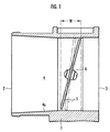
図1は内燃機関用のスロットル弁装置を示している。このスロットル弁装置は、スロットルボディ1を備えている。スロットルボディ1の内部には、エアクリーナ(図示せず)に接続される入口2と内燃機関の吸気マニホルド(図示せず)に接続される出口3とを結ぶ吸気通路4が形成されている。
FIG. 1 shows a throttle valve device for an internal combustion engine. The throttle valve device includes a
吸気通路4には、円形の板状のスロットル弁5が配置されている。スロットル弁5は、その所定の直径線上に固定した弁軸6を介してスロットルボディ1に回動自在に軸支される。そして、内燃機関用のコントローラで制御されるアクチュエータにより弁軸6を介してスロットル弁5を回動し、内燃機関への吸気量を制御する。コントローラは、内燃機関のアイドル運転時に、内燃機関の回転数が所定のアイドル回転数に維持されるように、スロットル弁5の開度を調節する。安全性を考慮して、アイドル運転状態を維持するためのスロットル弁5の開度調節範囲の上限(最大アイドル開度)が設定されており、アイドル運転状態では、スロットル弁5が最大アイドル開度を超えて開かれることはない。図1の2点鎖線はスロットル弁5が全閉であるときの状態を示し、実線はスロットル弁5が最大アイドル開度であるときの状態を示している。
A circular plate-
スロットル弁5の全閉から最大アイドル開度までの範囲でスロットル弁5の外周部に対向する吸気通路4の壁面4aの領域(以下、アイドル壁面領域という)に固形物が付着すると、スロットル弁5が最大アイドル開度に開かれても、吸気量不足でアイドル運転が不能になる可能性がある。
If solid matter adheres to the region of the wall surface 4a of the
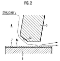
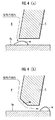
そこで、本実施形態では、図2に明示する如く、スロットル弁5の外周部に、空気の流れ方向上流側に位置させて、面取り部5aを設けている。ここで、面取り部5aの作用を図4を参照して説明する。図4(a)に示す如くスロットル弁5の外周部に面取り部を設けない場合は、上流側(エアクリーナ側)からの空気流がスロットル弁5に当たって径方向外方に流れ、スロットル弁5の外周部と吸気通路4の壁面4aとの間の隙間に径方向の大きな運動成分を持った状態で空気が流入する。そして、この隙間の空気の流入部分において、空気流に含まれる固形物aが吸気通路4の壁面4aに衝突し、この部分に固形物aが付着し易くなる。その結果、スロットル弁4の外周部と吸気通路4の壁面4aとの間の隙間が狭められ、アイドル運転状態での吸気量が減少する。一方、図4(b)に示す如くスロットル弁5の外周部に面取り部5aを設けると、スロットル弁5に当たって径方向外方に流れる空気流に面取り部5aで吸気通路4の軸方向の運動成分が与えられ、スロットル弁5の外周部と吸気通路4の壁面4aとの間の隙間に流入する際の空気流の径方向運動成分が減少する。そのため、この隙間における吸気通路4の壁面4aへの固形物aの衝突による付着が抑制される。然し、これだけでは、吸気通路4の壁面4aに固形物aが多少は付着してしまう。その原因は、吸気通路4の壁面4aに付着する油分であることが判明した。即ち、吸気通路4の壁面4aに固形物aが勢い良く衝突しなくても、油分の粘着力により固形物aが吸気通路4の壁面4aに付着してしまう。
Therefore, in the present embodiment, as clearly shown in FIG. 2, a chamfered portion 5a is provided on the outer peripheral portion of the
そこで、本実施形態では、図2に示すように、吸気通路4の壁面4aに、油分の付着を抑制するシリコーン等の油付着防止剤7を塗布している。油付着防止剤7の塗布領域は、アイドル壁面領域に対応する図1にWで示す軸方向範囲としている。尚、アイドル壁面領域外に亘って油付着防止剤7を塗布してもよいが、スロットル弁5の外周部がアイドル壁面領域から外れる状態ではスロットル弁5の開度が大きくなるため、壁面4aに固形物は殆ど付着しなくなる。従って、油付着防止剤7の塗布領域をアイドル壁面領域に限定しても不具合は生じない。
Therefore, in the present embodiment, as shown in FIG. 2, an oil
また、油付着防止剤7の塗布は、スロットル弁5をスロットルボディ1に組み込む前に液体状の油付着防止剤7を吸気通路4の壁面4aにスプレーし、乾燥させて油付着防止剤7の塗膜を形成することにより行う。この塗膜の厚さは、スロットル弁5の外周部との間の隙間が塗膜により狭められて吸気量の減少を生じないように、油分の付着防止効果を損なわない範囲で可及的に薄くする(例えば、1μm以内)。
The oil
上記の如く油付着防止剤7を塗布すると、アイドル壁面領域への油分の付着が抑制され、スロットル弁5の面取り部5aによる壁面4aへの固形物の衝突抑制効果と相俟って、アイドル壁面領域での固形物の付着が有効に防止される。従って、固形物の付着による吸気量の減少でアイドル運転が不能になることを確実に防止できる。
When the oil adhesion
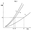
図3はスロットル弁5の開度に対する吸気流量の変化特性を示している。同図のA線は吸気通路4の壁面4aに固形物が付着していない初期状態での特性、B線は、上記実施形態のスロットル装置を用い、固形物が付着しやすい運転状態で内燃機関を24時間稼動した後の特性である。また、図4(a)に示した従来構造のスロットル弁装置を用い、固形物が付着しやすい運転状態で内燃機関を24時間稼動した後の特性は図3のC線のようになった。流量Q1は、アイドル運転時の吸気流量である。この流量Q1を得るのに必要なスロットル弁5の開度(アイドル開度)は、初期状態ではθa(例えば、2°)である。従来のスロットル弁装置を用いた場合、24時間稼動後のアイドル開度はθc(例えば、5°)まで大幅に増加する。これに対し、本実施形態のスロットル弁装置を用いた場合は、24時間稼動後のアイドル開度はθaより若干大きなθb(例えば、2.5°)に増加するものの、増加量は従来のスロットル弁装置に比し大幅に減少している。ここで、アイドル開度が増加するのはアイドル壁面領域に付着した固化物の影響であり、本実施形態のスロットル弁装置によれば、固化物の付着が有効に防止されることが分かる。
FIG. 3 shows a change characteristic of the intake flow rate with respect to the opening degree of the
1…スロットルボディ、4…吸気通路、4a…壁面、5…スロットル弁、5a…面取り部、6…弁軸、7…油付着防止剤。
DESCRIPTION OF
Claims (2)
前記スロットル弁の外周部に面取り部が設けられると共に、前記吸気通路の壁面に、油分の付着を抑制する油付着防止剤が塗布されていることを特徴とする内燃機関用のスロットル弁装置。 An internal combustion engine comprising: a throttle body having an intake passage for the internal combustion engine therein; and a plate-like throttle valve disposed in the intake passage and rotatably supported by the throttle body via a valve shaft In the throttle valve device of
A throttle valve device for an internal combustion engine, wherein a chamfered portion is provided on an outer peripheral portion of the throttle valve, and an oil adhesion preventing agent for suppressing adhesion of oil is applied to a wall surface of the intake passage.
Priority Applications (1)
| Application Number | Priority Date | Filing Date | Title |
|---|---|---|---|
| JP2004108917A JP2005291127A (en) | 2004-04-01 | 2004-04-01 | Throttle valve device for internal combustion engine |
Applications Claiming Priority (1)
| Application Number | Priority Date | Filing Date | Title |
|---|---|---|---|
| JP2004108917A JP2005291127A (en) | 2004-04-01 | 2004-04-01 | Throttle valve device for internal combustion engine |
Publications (1)
| Publication Number | Publication Date |
|---|---|
| JP2005291127A true JP2005291127A (en) | 2005-10-20 |
Family
ID=35324335
Family Applications (1)
| Application Number | Title | Priority Date | Filing Date |
|---|---|---|---|
| JP2004108917A Pending JP2005291127A (en) | 2004-04-01 | 2004-04-01 | Throttle valve device for internal combustion engine |
Country Status (1)
| Country | Link |
|---|---|
| JP (1) | JP2005291127A (en) |
-
2004
- 2004-04-01 JP JP2004108917A patent/JP2005291127A/en active Pending
Similar Documents
| Publication | Publication Date | Title |
|---|---|---|
| US5749336A (en) | Intake valve control system for internal combustion engine | |
| JP4492696B2 (en) | Fuel injection valve | |
| US7213586B2 (en) | Exhaust gas recirculation valve | |
| US20100065026A1 (en) | Exhaust gas recirculation valve | |
| US6176467B1 (en) | Control valve device | |
| US20100065027A1 (en) | Exhaust gas recirculation valve | |
| JP2005291127A (en) | Throttle valve device for internal combustion engine | |
| US7104522B2 (en) | Coking-resistant shaft/bushing mechanism for an exhaust gas recirculation valve | |
| JP6862479B2 (en) | Valve device | |
| JP2008232001A (en) | Throttle body and plastic throttle valve | |
| JPS6154937B2 (en) | ||
| JPS6220363B2 (en) | ||
| JP4458023B2 (en) | Control device for internal combustion engine | |
| JP2000110951A (en) | Butterfly valve | |
| JP2014092113A (en) | Valve device | |
| JP3292945B2 (en) | Exhaust gas recirculation device | |
| JP2006029469A (en) | Air flow control valve | |
| JP3347906B2 (en) | Intake valve device | |
| JP6387771B2 (en) | Valve mechanism | |
| JP2011001862A (en) | Throttle control device for internal combustion engine | |
| JP2000120451A (en) | Intake control device for internal combustion engine | |
| JP2001082183A (en) | Throttle valve device for internal combustion engine | |
| JP3780250B2 (en) | Motor-driven throttle valve device | |
| JP3958904B2 (en) | Engine intake air amount control device | |
| JP2000054859A (en) | Intake control device for internal combustion engine |