JP2005291118A - Control device for internal combustion engine provided with valve opening characteristic adjusting device - Google Patents
Control device for internal combustion engine provided with valve opening characteristic adjusting device Download PDFInfo
- Publication number
- JP2005291118A JP2005291118A JP2004108615A JP2004108615A JP2005291118A JP 2005291118 A JP2005291118 A JP 2005291118A JP 2004108615 A JP2004108615 A JP 2004108615A JP 2004108615 A JP2004108615 A JP 2004108615A JP 2005291118 A JP2005291118 A JP 2005291118A
- Authority
- JP
- Japan
- Prior art keywords
- valve opening
- internal combustion
- combustion engine
- cylinder group
- opening characteristic
- Prior art date
- Legal status (The legal status is an assumption and is not a legal conclusion. Google has not performed a legal analysis and makes no representation as to the accuracy of the status listed.)
- Pending
Links
Images


Landscapes
- Valve Device For Special Equipments (AREA)
- Output Control And Ontrol Of Special Type Engine (AREA)
- Electrical Control Of Air Or Fuel Supplied To Internal-Combustion Engine (AREA)
- Combined Controls Of Internal Combustion Engines (AREA)
Abstract
【課題】
バルブ開特性調整機構によって生じる気筒群間の空燃比のずれをバルブ開特性の差から予め求めて補正する内燃機関の制御装置を提供する。
【解決手段】
吸気バルブ及び/又は排気バルブ開特性調整装置を備えた複数の気筒群を持つ内燃機関の制御装置において、該制御装置は、気筒群毎に前記バルブの実位相を算出する手段と、前記内燃機関の全気筒の吸入空気量を求める手段とを有し、前記バルブの実位相から気筒群毎の充填率を求め、充填率から各気筒群の吸入空気量の分配比率を求めることにより、各気筒群の燃料噴射量を補正する。
【選択図】図4
【Task】
Provided is a control device for an internal combustion engine that corrects a deviation in air-fuel ratio between cylinder groups, which is caused by a valve opening characteristic adjusting mechanism, by obtaining in advance from a difference in valve opening characteristics.
[Solution]
In a control device for an internal combustion engine having a plurality of cylinder groups provided with an intake valve and / or exhaust valve opening characteristic adjustment device, the control device includes means for calculating the actual phase of the valve for each cylinder group, and the internal combustion engine Means for determining the intake air amount of all cylinders of the cylinders, determining the filling rate for each cylinder group from the actual phase of the valve, and determining the distribution ratio of the intake air amount for each cylinder group from the filling rate. Correct the fuel injection amount of the group.
[Selection] Figure 4
Description
この発明は内燃機関の運転中に吸気バルブ又は排気バルブの少なくともいずれか一方のバルブ開特性を制御するバルブ開特性調整装置に係り、詳しくは各気筒を複数の気筒群に分けて配置してなる内燃機関における制御装置に関するものである。 The present invention relates to a valve opening characteristic adjusting device for controlling the valve opening characteristic of at least one of an intake valve and an exhaust valve during operation of an internal combustion engine, and more specifically, each cylinder is divided into a plurality of cylinder groups. The present invention relates to a control device in an internal combustion engine.
従来、バルブ開特性調整装置を備えた内燃機関の制御装置として、気筒群ごとにバルブ開特性が異なることにより各気筒群間の吸入空気量差を生じる場合に、各気筒群の吸気管圧力が等しくなるようバルブ開特性調整量を制御して気筒群間の燃焼状態を等しくすることが行われている(例えば特許文献1参照)。 Conventionally, as a control device for an internal combustion engine equipped with a valve opening characteristic adjusting device, when the intake air amount difference between each cylinder group is caused by the valve opening characteristic being different for each cylinder group, the intake pipe pressure of each cylinder group is The valve opening characteristic adjustment amount is controlled so as to be equal to make the combustion state between the cylinder groups equal (for example, refer to Patent Document 1).
ところで気筒群毎に個々にバルブ開特性調整装置を備えている場合、単にその気筒群毎にバルブ開特性調整装置を同一に制御するだけでは、気筒群毎の応答性の違いにより気筒群間の吸入空気量に差が発生し、燃焼不良による振動や、空燃比が理論空燃比からずれることによる排気ガス悪化の問題が生ずる。 By the way, when the valve opening characteristic adjusting device is individually provided for each cylinder group, simply controlling the valve opening characteristic adjusting device for each cylinder group in the same way causes the difference in response between the cylinder groups. A difference occurs in the intake air amount, causing problems due to vibration due to poor combustion and exhaust gas deterioration due to deviation of the air-fuel ratio from the stoichiometric air-fuel ratio.
また、気筒群毎に異なったバルブ開特性として運転するべく各気筒群のバルブ開特性調整装置を独立して制御する内燃機関の場合も同様に、各気筒群間の吸入空気量に差が発生し、燃焼不良による振動や、空燃比が理論空燃比からずれることによる排気ガス悪化の問題が生ずる。 Similarly, in the case of an internal combustion engine that controls the valve opening characteristic adjusting device of each cylinder group independently to operate with different valve opening characteristics for each cylinder group, a difference occurs in the intake air amount between the cylinder groups. However, there are problems of vibration due to poor combustion and exhaust gas deterioration due to deviation of the air-fuel ratio from the stoichiometric air-fuel ratio.
すなわち、複数の気筒群を持つ内燃機関の場合、気筒群毎に作動油経路が異なることによる油圧の移送遅れの違いや、動弁機構部品の加工精度のばらつきに起因する摩擦力の違いにより各気筒群間のバルブ開特性調整装置の動作速度が異なるため、各気筒群間のバルブ開特性に過渡的な違いが発生し、各気筒群間の吸入空気量差を生じる場合がある。 That is, in the case of an internal combustion engine having a plurality of cylinder groups, each of the cylinder groups has a difference in hydraulic oil transfer delay due to different hydraulic oil paths, and a difference in frictional force due to variations in processing accuracy of valve mechanism parts. Since the operating speeds of the valve opening characteristic adjusting devices between the cylinder groups are different, there may be a transient difference in the valve opening characteristics between the cylinder groups, resulting in a difference in intake air amount between the cylinder groups.
また、内燃機関のポンプ損失を減らすために一部の気筒群の吸入空気量を減らすべくバルブ開特性を制御する場合も同様に、各気筒群間の吸入空気量差を生じる。このような場合に、全ての気筒群に対して同様の燃料噴射を行えば、トルク変動が発生し、空燃比が目標値からずれるとともに、排気ガス悪化の問題がある。 Similarly, when the valve opening characteristic is controlled to reduce the intake air amount of some cylinder groups in order to reduce the pump loss of the internal combustion engine, a difference in intake air amount between the cylinder groups is generated. In such a case, if the same fuel injection is performed for all the cylinder groups, torque fluctuations occur, the air-fuel ratio deviates from the target value, and exhaust gas deteriorates.
これらの問題を解決するため、従来は気筒群毎に独立した吸気管と、吸気管毎に吸入空気量を検出する装置を設け、気筒群毎に吸入空気量を求める手段が存在しているが、気筒群毎に吸気管および吸入空気量検出装置を設置すれば、制御装置の複雑化や製品コストの増加を招くなどの欠点がある。 In order to solve these problems, there has conventionally been a means for obtaining an intake air amount for each cylinder group by providing an independent intake pipe for each cylinder group and a device for detecting the intake air amount for each intake pipe. If an intake pipe and an intake air amount detection device are installed for each cylinder group, there are disadvantages such as a complicated control device and an increase in product cost.
この発明の目的は複数の気筒群と、各気筒群が共有する吸気管とを持つ内燃機関において、各気筒群間のバルブ開特性が異なる場合、気筒群毎に該気筒群のバルブ開特性から燃料噴射量の補正を行うことにより、トルク変動を抑制し、空燃比を目標値に近付けるとともに排気ガス悪化を抑止することができる内燃機関の制御装置を提供することにある。 In an internal combustion engine having a plurality of cylinder groups and an intake pipe shared by each cylinder group, an object of the present invention is that the valve opening characteristics of each cylinder group differ from each other when the valve opening characteristics between the cylinder groups differ. An object of the present invention is to provide a control device for an internal combustion engine that can suppress fluctuations in torque, bring an air-fuel ratio closer to a target value, and suppress exhaust gas deterioration by correcting the fuel injection amount.
請求項1に記載の内燃機関の制御装置は、複数気筒エンジンの各気筒がクランクシャフトを中心に複数位置に分けて配置されてなる各気筒群と、
前記各気筒群における吸気バルブまたは排気バルブのいずれか一方または両方に対するバルブ開特性を可変するバルブ開特性調整装置と、
前記各気筒群におけるバルブ開特性を同位相または別位相で制御すべく前記エンジンの運転状態に応じて前記バルブ開特性調整装置を駆動制御する駆動制御手段とを備えており、
前記バルブ開特性調整装置によって検出された前記各気筒群のバルブ開特性調整量を、前記各気筒群に噴射する燃料量を求める手段として利用することを特徴とする。
The control device for an internal combustion engine according to
A valve opening characteristic adjusting device that varies a valve opening characteristic for one or both of the intake valve and the exhaust valve in each cylinder group; and
Drive control means for driving and controlling the valve opening characteristic adjusting device in accordance with the operating state of the engine so as to control the valve opening characteristic in each of the cylinder groups in the same phase or in another phase;
The valve opening characteristic adjustment amount of each cylinder group detected by the valve opening characteristic adjustment device is used as means for obtaining the amount of fuel injected into each cylinder group.
このように、内燃機関の気筒群毎のバルブ開特性に応じて該気筒群に噴射する燃料量を適正に算出することにより、トルク変動および排気ガス悪化を防止することができる。 Thus, torque fluctuation and exhaust gas deterioration can be prevented by appropriately calculating the amount of fuel injected into the cylinder group in accordance with the valve opening characteristics of each cylinder group of the internal combustion engine.
請求項2に記載の内燃機関の制御装置は、複数気筒エンジンの各気筒がクランクシャフトを中心に複数位置に分けて配置されてなる各気筒群と、
前記エンジンの全気筒の吸入空気量を計測する吸入空気量検出手段と、
前記各気筒群における吸気バルブまたは排気バルブのいずれか一方または両方に対するバルブ開特性を可変するバルブ開特性調整装置と、
前記各気筒群におけるバルブ開特性を同位相または別位相で制御すべく前記エンジンの運転状態に応じて前記バルブ開特性調整装置を駆動制御する駆動制御手段とを備えており、
前記全気筒の吸入空気量と前記バルブ開特性調整装置によって検出された前記各気筒群のバルブ開特性調整量とにより前記各気筒群の吸入空気量を求めることを特徴とする。
The control device for an internal combustion engine according to
Intake air amount detection means for measuring the intake air amount of all cylinders of the engine;
A valve opening characteristic adjusting device that varies a valve opening characteristic for one or both of the intake valve and the exhaust valve in each cylinder group; and
Drive control means for driving and controlling the valve opening characteristic adjusting device in accordance with the operating state of the engine so as to control the valve opening characteristic in each of the cylinder groups in the same phase or in another phase;
The intake air amount of each cylinder group is obtained from the intake air amount of all the cylinders and the valve opening characteristic adjustment amount of each cylinder group detected by the valve opening characteristic adjusting device.
このように、内燃機関の気筒群毎のバルブ開特性に応じてその気筒群の吸入空気量を求めることにより、気筒群毎の吸入空気量から求められる該気筒群に噴射する燃料量が適正な値となりトルク変動および排気ガス悪化を防止することができる。 Thus, by obtaining the intake air amount of each cylinder group according to the valve opening characteristics of each cylinder group of the internal combustion engine, the amount of fuel injected into the cylinder group obtained from the intake air amount for each cylinder group is appropriate. Thus, torque fluctuations and exhaust gas deterioration can be prevented.
請求項3に記載の内燃機関の制御装置は、請求項2に記載の構成に対して前記各気筒群のバルブ開特性調整量より前記各気筒群の吸気充填率をそれぞれ求めることにより前記各気筒群の吸入空気量をそれぞれ求めることを特徴とする。 According to a third aspect of the present invention, there is provided a control device for an internal combustion engine, wherein the control unit according to the second aspect obtains the intake charge rate of each cylinder group from the valve opening characteristic adjustment amount of each cylinder group. It is characterized in that the intake air amount of each group is obtained.
このように、気筒群毎に吸入空気量検出装置を設けなくとも、気筒群毎のバルブ開特性調整量より気筒群毎に吸気充填率を求め、それらの吸気充填率と全気筒の吸入空気量から気筒群毎の吸入空気量を求めることができる。 Thus, without providing an intake air amount detection device for each cylinder group, the intake charge rate is obtained for each cylinder group from the valve opening characteristic adjustment amount for each cylinder group, and the intake charge rate and intake air amount for all cylinders are obtained. Thus, the intake air amount for each cylinder group can be obtained.
請求項4に記載の内燃機関の制御装置は、請求項1〜3のいずれか記載の構成に対して、前記バルブ開特性調整装置の調整量を前記気筒群ごとにそれぞれ独立して制御することを特徴とする。
The control device for an internal combustion engine according to
このように、気筒群毎に吸入空気量または燃料噴射量を求めることが可能な内燃機関では、気筒群毎にバルブ開特性を独立に制御することができ、内燃機関のポンプ損失を低減して燃費向上の効果を得ることができる。 Thus, in an internal combustion engine that can determine the intake air amount or the fuel injection amount for each cylinder group, the valve opening characteristics can be controlled independently for each cylinder group, reducing the pump loss of the internal combustion engine. The effect of improving fuel consumption can be obtained.
以上の説明から理解されるように、本発明に係る内燃機関の制御装置は、気筒群毎にバルブ開特性調整装置の調整量が異なっている状態でも、その調整量から気筒群毎に燃料噴射量を算出して空燃比を好適に制御することが可能になる。 As can be understood from the above description, the control device for an internal combustion engine according to the present invention performs fuel injection for each cylinder group from the adjustment amount even when the adjustment amount of the valve opening characteristic adjustment device is different for each cylinder group. It becomes possible to control the air-fuel ratio by calculating the amount.
そのため、トルク変動が抑制されて運転性が向上するほか、排気ガスの悪化を防止することが可能になるという優れた効果を奏する。 Therefore, the torque fluctuation is suppressed and the drivability is improved, and the excellent effect is obtained that it is possible to prevent the exhaust gas from deteriorating.
以下、図面により本発明に係るバルブ開特性調整装置を備えた内燃機関の制御装置の一実施形態について詳細に説明する。 Hereinafter, an embodiment of a control device for an internal combustion engine provided with a valve opening characteristic adjusting device according to the present invention will be described in detail with reference to the drawings.
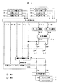
図1は、本実施形態のバルブ開特性調整装置を備えた内燃機関の全体のシステム構成を示したものである。 FIG. 1 shows the overall system configuration of an internal combustion engine provided with the valve opening characteristic adjusting device of this embodiment.
この実施の形態では多気筒V型内燃機関1の各気筒は、クランクシャフト2を共有する気筒群3,4に配置され、気筒群3に含まれる各気筒は、吸気カムシャフト5,排気カムシャフト12を共有し、気筒群4に含まれる各気筒は、吸気カムシャフト6,排気カムシャフト13を共有している。
In this embodiment, each cylinder of the multi-cylinder V-type
気筒群3,4はそれぞれ同数の気筒により構成される。
Each of the
各気筒群3,4に設けられた吸気カムシャフト5,6の一端には、同カムシャフト5,6によって開閉動作される吸気バルブ16,17の開閉タイミングを可変にする位相可変カムプーリ7,8がそれぞれ設けられている。
At one end of
この位相可変カムプーリは、連続位相可変型とされている。 This phase variable cam pulley is a continuous phase variable type.
各気筒群3,4に設けられた排気カムシャフト12,13の一端には、位相が変化しないカムプーリ14,15がそれぞれ設けられている。
クランクシャフト2にはクランクプーリ40が固定されている。
A
位相可変カムプーリ7,8,カムプーリ14,15はタイミングベルト10を介しクランクプーリ40によって駆動される。
The phase
テンショナプーリ11はタイミングベルト10に張力を付加し、クランクプーリ40による位相可変カムプーリ7,8,カムプーリ14,15の駆動を補助する。各位相可変カムプーリ7,8には、油圧によって駆動されるアクチュエータが内蔵されている。
The tensioner pulley 11 applies tension to the
位相可変カムプーリの構造については周知であるため説明を省略する。 Since the structure of the phase variable cam pulley is well known, description thereof is omitted.
クランクシャフト2またはモータの回転力によって駆動されるオイルポンプ46は内燃機関の下部よりオイル45を吸い上げ、オイル通路48に油圧を供給する。オイルコントロールバルブ(OCV)35,36は位相可変油圧通路49,50を介してオイル通路
48に供給された油圧を各位相可変カムプーリ7,8に供給する。
The
位相可変油圧通路49,50はそれぞれ位相可変カムプーリの図示しない進角室と遅角室につながる2本の油圧通路から構成されており、進角室と遅角室のどちらか一方にのみ油圧が供給される場合は、もう一方のオイルはOCVを介して図示しないドレーン通路に排出され、内燃機関下部に戻される。
The phase variable
位相可変カムプーリ7,8は油圧の供給を受けて吸気カムシャフト5,6に回転方向の作動を生じさせ、クランクシャフト2に対して吸気カムシャフト5,6の位相が変化する。
The variable
クランクシャフト2には、クランクシャフト2の回転位置および回転速度(すなわち、内燃機関1の回転速度NE)を検出するためのクランク角センサ32が設けられている。
The
吸気カムシャフト5,6の回転位置をそれぞれ求めるためのカム角センサ33,34が吸気カムシャフト5,6に設けられている。
クランク角センサ32とカム角センサ33の出力信号の位相差により気筒群3の実吸気カムシャフト位相VTAおよび吸気バルブ16の実開閉タイミングが求められる。
The actual intake camshaft phase VTA of the
クランク角センサ32とカム角センサ34の出力信号の位相差により気筒群4の実吸気カムシャフト位相VTBおよび吸気バルブ17の開閉タイミングが求められる。
The actual intake camshaft phase VTB of the
また、前記気筒群3,4の各気筒の燃焼室には吸気管9および排気管20,21が連通して設けられている。
An
吸気管9の燃焼室に開口する吸気ポートには、開閉用の吸気バルブ16,17が組付けられている。
Opening and
また、排気管20,21の燃焼室に開口する排気ポートには、開閉用の排気バルブ18,19が組付けられている。
In addition, opening and closing
吸気管9にはエアクリーナ39を介して外気が導入される。
Outside air is introduced into the
また、吸気管9にはその吸気ポートの近傍において燃料噴射用のインジェクタ28,
29が設けられ、燃料配管30,31に供給された燃料が吸気ポートに取り込まれるようになっている。
The
29 is provided so that the fuel supplied to the
吸気管9の途中には、スロットルバルブ38が設けられている。
A
そして、このスロットルバルブ38が開閉されることにより、吸気管9への吸入空気量が調節される。
The
さらに、スロットルバルブ38よりも上流側には、吸気管9に取込まれる吸入空気量Qを検出する周知のエアフローセンサ37が設けられている。
Further, a known
吸気管9は気筒群3,4に共有され、スロットルバルブ38を通過した吸入空気は気筒群3または気筒群4へと分配される。
The
スロットルバルブの開度THはスロットル開度センサ52によって検出される。一方、排気管20,21の途中に設けられた空燃比センサ24,25は、排気ガス中の成分から空燃比に応じた信号を出力し、気筒群3,4の吸入空気量に対する燃料の過不足状態AFA,AFBが求められる。
The throttle valve opening TH is detected by a
気筒群3,4の燃焼室には点火プラグ26,27が設けられている。
Spark plugs 26 and 27 are provided in the combustion chambers of the
また、気筒群3,4の燃焼室には、コネクティングロッド43,44を介してクランクシャフト2に駆動されて往復動作するピストン41,42が設けられる。これら点火プラグ26,27,クランクシャフト2,コネクティングロッド43,44,ピストン41,42の動作については周知であるので説明は省略する。この実施の形態では前記各種センサ等24,25,32〜34,37,52の各信号がエンジンコントロールユニット
(ECU)51に入力され、内燃機関1の運転状態が検出される。
Further,
ECU51は前記検出された運転状態に基づき、インジェクタ28,29およびOCV35,36を制御する。
The
また、ECU51は図示しない点火回路を介して点火プラグ26,27を制御する。
The
ECU51は図示しない入力回路,出力回路,演算装置,記憶装置を備える。
The
ECU51が備えるこれらの回路および装置の構成は周知のものとし、説明は省略する。
The configurations of these circuits and devices provided in the
ECU51はカムシャフト位相制御量算出手段,カムシャフト位相制御手段,吸入空気量算出手段,吸入空気量補正手段,燃料噴射量算出手段,燃料噴射量補正手段,燃料噴射量制御手段を構成する。
The
以下、カムシャフト位相制御について説明する。 Hereinafter, camshaft phase control will be described.
図2にカムシャフト位相制御の制御ブロック図を示す。 FIG. 2 shows a control block diagram of camshaft phase control.
ECU51はTH,NE,Lにより内燃機関1の運転状態を検出し、カムシャフト位相の制御目標値VTを所定値に固定するか、またはTH,NE,Lによって最適なバルブ開特性となるようVTの算出を行う。
The
そして、算出されたVTにVTA,VTBが一致するよう、OCV35,36をフィードバック制御する。
Then, the
OCVのフィードバック制御方法は周知であるので説明は省略する。 Since the OCV feedback control method is well known, the description thereof is omitted.
図3はカムシャフト位相制御に対する気筒群3,4の吸気カムシャフトの実位相を示したものである。
FIG. 3 shows the actual phases of the intake camshafts of the
VTが変化したとき、VTAとVTBはそれぞれVTに近づくように動作するが、VTAとVTBの変化速度には違いがあり、動作中は気筒群3,4の吸気カムシャフト位相に差が生じている。
When VT changes, VTA and VTB operate so as to approach VT, respectively, but there is a difference in the changing speed of VTA and VTB, and there is a difference in the intake camshaft phases of
これは機械配置上の制約などにより気筒群3と気筒群4が全く同様な構造となることはなく、また、構成部品の加工精度ばらつきによりカムシャフト位相制御に対する気筒群3と気筒群4のカムシャフト位相変化応答性が異なることにより発生するものである。
This is because the
また、OCVおよびその駆動回路やハーネスの故障,油圧通路の詰まりによりカムシャフトの位相が制御不可能になる場合は、定常的に気筒群3と気筒群4のカムシャフト位相に差が生じる。
In addition, when the camshaft phase becomes uncontrollable due to the failure of the OCV and its drive circuit or harness, or the clogging of the hydraulic passage, the camshaft phase between the
さらには、内燃機関1のポンプ損失を低減する目的で、吸入空気量を減らすべく気筒群3,4のうちいずれか一方の気筒群のみカムシャフト位相を所定値に制御する場合がある。
Furthermore, in order to reduce the pump loss of the
この場合も定常的に気筒群3と気筒群4のカムシャフト位相に差が生じる。
Also in this case, there is a constant difference between the camshaft phases of the
次に、気筒群毎に吸入空気量および燃料噴射量を求める方法を説明する。 Next, a method for obtaining the intake air amount and the fuel injection amount for each cylinder group will be described.
図4に燃料噴射量制御のブロック図を示す。 FIG. 4 shows a block diagram of the fuel injection amount control.
図5に示されるように、VTA,VTBによって各気筒群3,4の吸気バルブ開特性は変化する。
As shown in FIG. 5, the intake valve opening characteristics of the
図5で示されるSは吸入空気量が最大となるカムシャフト位相時のピストンストローク、Aは吸気行程中で吸気バルブが開いているときのピストンストローク、Bは圧縮行程中で吸気バルブが開いているときのピストンストロークである。 In FIG. 5, S is the piston stroke at the camshaft phase where the intake air amount is maximum, A is the piston stroke when the intake valve is open during the intake stroke, and B is the intake valve open during the compression stroke. This is the piston stroke.
各気筒群3,4の吸気充填率EはS,A,Bを用いて以下に算出される。
The intake air filling rate E of each of the
(数1)
E={A・(Pi−Pc)+B・(Pc−Pi)}/S・(Pi−Pc)
ここで、Piは吸気管の圧力、Pcは燃焼室の圧力である。
(Equation 1)
E = {A · (Pi−Pc) + B · (Pc−Pi)} / S · (Pi−Pc)
Here, Pi is the pressure in the intake pipe, and Pc is the pressure in the combustion chamber.
気筒群3の吸気充填率をEA,気筒群4の吸気充填率をEBとすると、EA,EBは該気筒群の吸気バルブ開特性を用いて(数1)のEと同様に求められる。
Assuming that the intake charge rate of the
また、EA,EBはVTA,VTBをパラメータとするテーブルとして予め設定しておくことも可能であり、図6で示されるようなテーブルによって求めることもできる。 Further, EA and EB can be set in advance as a table using VTA and VTB as parameters, and can also be obtained by a table as shown in FIG.
EA,EBを用いれば、気筒群3,4に分配される吸入空気量の比率RA,RBを以下の式に求めることができる。
If EA and EB are used, the ratios RA and RB of the intake air amounts distributed to the
(数2)
RA=EA/(EA+EB)
RB=EB/(EA+EB)
ここで、RBはRAを用いると、RB=1−RAと表すことができる。
(Equation 2)
RA = EA / (EA + EB)
RB = EB / (EA + EB)
Here, RB can be expressed as RB = 1−RA when RA is used.
吸気管に取り込まれる吸入空気量QとRAを用いれば、気筒群3,4の吸入空気量QA,QBは以下の式で求められる。
If the intake air amounts Q and RA taken into the intake pipe are used, the intake air amounts QA and QB of the
(数3)
QA=Q・RA
QB=Q・(1−RA)
ECU51は、QA,QBと回転速度NEを用いて以下の式により気筒群3,4の負荷LA,LBを算出する。
(Equation 3)
QA = Q ・ RA
QB = Q · (1-RA)
The
(数4)
LA=(QA/NE)
LB=(QB/NE)
ECU51は、LA,LBを用いて以下の式により気筒群3,4の燃料噴射量TA,
TBを算出する。
(Equation 4)
LA = (QA / NE)
LB = (QB / NE)
The
TB is calculated.
(数5)
TA=LA・K・GA
TB=LB・K・GB
ここで、Kは目標空燃比と各気筒群の気筒数から求められる係数であり、GA,GBはAFA,AFBと内燃機関の運転状態から算出された空燃比フィードバック制御補正係数である。
(Equation 5)
TA = LA ・ K ・ GA
TB = LB ・ K ・ GB
Here, K is a coefficient obtained from the target air-fuel ratio and the number of cylinders in each cylinder group, and GA and GB are air-fuel ratio feedback control correction coefficients calculated from AFA, AFB and the operating state of the internal combustion engine.
ECU51はQとNEを用いて以下の式により内燃機関1の負荷Lを算出する。
The
(数6)
L=Q/NE
ECU51はTA,TBによって出力回路を駆動し、インジェクタ28,29より噴射される燃料の量を制御する。
(Equation 6)
L = Q / NE
The
以上、本発明のいくつかの実施例を備えた実施形態について詳述したが、本発明は、前記実施形態に限定されるものではなく、特許請求の範囲に記載された本発明の精神を逸脱することなく、設計において種々の変更ができるものである。
(1)前記実施形態では、吸気バルブのバルブ開特性調整装置を備えた内燃機関について記載したが、吸気バルブおよび排気バルブのバルブ開特性調整装置を備えた内燃機関であっても適用できるものであることは明らかである。
(2)前記実施形態においては、可変バルブタイミング調整装置に関して記載したが、可変バルブリフト制御装置であっても良いものである。
(3)前記実施形態では、吸入空気量を直接計測するエアフローセンサを採用しているが、吸気管の圧力と機関の回転速度を利用して吸入空気量を間接的に計測する手段を備えた内燃機関に適用することも可能である。
(4)前記実施形態では、油圧によってバルブ開特性が変化する構造を採用しているが、電磁力を利用してバルブ開特性を変化させる装置に適用することも可能である。
(5)前記実施形態では、吸気ポートを含む吸気管内に燃料を噴射する内燃機関について記載したが、燃焼室内に燃料を噴射する内燃機関に適用することも可能である。
(6)前記実施形態では、火花によって点火される内燃機関について記載したが、ディーゼルエンジン等自己着火の内燃機関に適用することも可能である。
(7)前記実施形態では、V型内燃機関について記載したが、水平対抗型内燃機関およびW型内燃機関など複数の気筒群を持つ内燃機関であればいずれにも適用することが可能である。
As mentioned above, although the embodiment provided with some examples of the present invention was described in detail, the present invention is not limited to the above-mentioned embodiment, and departs from the spirit of the present invention described in the claims. It is possible to make various changes in the design without doing so.
(1) In the above embodiment, the internal combustion engine provided with the valve opening characteristic adjusting device for the intake valve has been described. However, the present invention can also be applied to an internal combustion engine provided with the valve opening characteristic adjusting device for the intake valve and the exhaust valve. It is clear that there is.
(2) Although the variable valve timing adjusting device has been described in the above embodiment, a variable valve lift control device may be used.
(3) In the above embodiment, an air flow sensor that directly measures the intake air amount is employed, but a means for indirectly measuring the intake air amount using the pressure of the intake pipe and the rotational speed of the engine is provided. It is also possible to apply to an internal combustion engine.
(4) In the above-described embodiment, the structure in which the valve opening characteristic is changed by the hydraulic pressure is adopted, but the present invention can be applied to a device that changes the valve opening characteristic by using electromagnetic force.
(5) In the above embodiment, the internal combustion engine that injects fuel into the intake pipe including the intake port has been described. However, the present invention can also be applied to an internal combustion engine that injects fuel into the combustion chamber.
(6) In the above-described embodiment, the internal combustion engine that is ignited by a spark has been described. However, it can also be applied to a self-ignition internal combustion engine such as a diesel engine.
(7) Although the V-type internal combustion engine has been described in the above embodiment, the present invention can be applied to any internal combustion engine having a plurality of cylinder groups such as a horizontally opposed internal combustion engine and a W-type internal combustion engine.
1…内燃機関、2…クランクシャフト、3,4…気筒群、5,6…吸気カムシャフト、7,8…位相可変カムプーリ、9…吸気管、10…タイミングベルト、11…テンショナプーリ、12,13…排気カムシャフト、14,15…カムプーリ、16,17…吸気バルブ、18,19…排気バルブ、20,21…排気管、22,23…触媒、24,25…空燃比センサ、26,27…点火プラグ、28,29…インジェクタ、30,31…燃料配管、32…クランク角センサ、33,34…カム角センサ、35,36…オイルコントロールバルブ(OCV)、37…エアフローセンサ、38…スロットルバルブ、39…エアクリーナ、40…クランクプーリ、41,42…ピストン、43,44…コネクティングロッド、45…オイル、46…オイルポンプ、47…オイル吸入通路、48…オイル通路、49,50…位相可変油圧通路、51…エンジンコントロールユニット(ECU)、52…スロットル開度センサ。
DESCRIPTION OF
Claims (4)
少なくとも吸気バルブ開特性調整装置は排気バルブ開特性調整装置のいずれかを有し、
前記バルブ開特性調整装置の調整量検出手段とを備え、
前記複数の気筒は2つ以上の気筒群に分けられ、
前記調整量が前記気筒群によって異なる場合に
前記調整量を用いて各気筒群に噴射する燃料量をそれぞれ求める手段を有する内燃機関の制御装置。 In an internal combustion engine having a plurality of cylinders,
At least the intake valve opening characteristic adjusting device has one of the exhaust valve opening characteristic adjusting device,
An adjustment amount detecting means of the valve opening characteristic adjusting device,
The plurality of cylinders are divided into two or more cylinder groups,
A control apparatus for an internal combustion engine, having means for determining the amount of fuel injected into each cylinder group using the adjustment amount when the adjustment amount varies depending on the cylinder group.
全気筒の吸入空気量を計測する吸入空気量検出手段と、
少なくとも吸気バルブ開特性調整装置は排気バルブ開特性調整装置のいずれかを有し、
前記バルブ開特性調整装置の調整量検出手段とを備え、
前記複数の気筒は2つ以上の気筒群に分けられ、
前記調整量が前記気筒群によって異なる場合に
前記全気筒の吸入空気量と前記バルブ開特性調整装置の調整量とを用いて各気筒群の吸入空気量をそれぞれ求める手段を有する内燃機関の制御装置。 In an internal combustion engine having a plurality of cylinders,
Intake air amount detection means for measuring the intake air amount of all cylinders;
At least the intake valve opening characteristic adjusting device has one of the exhaust valve opening characteristic adjusting device,
An adjustment amount detecting means of the valve opening characteristic adjusting device,
The plurality of cylinders are divided into two or more cylinder groups,
A control device for an internal combustion engine, having means for determining the intake air amount of each cylinder group using the intake air amount of all the cylinders and the adjustment amount of the valve opening characteristic adjusting device when the adjustment amount differs depending on the cylinder group .
The control device for an internal combustion engine according to any one of claims 1 to 3, wherein an adjustment amount of the valve opening characteristic adjusting device is controlled independently for each cylinder group.
Priority Applications (1)
| Application Number | Priority Date | Filing Date | Title |
|---|---|---|---|
| JP2004108615A JP2005291118A (en) | 2004-04-01 | 2004-04-01 | Control device for internal combustion engine provided with valve opening characteristic adjusting device |
Applications Claiming Priority (1)
| Application Number | Priority Date | Filing Date | Title |
|---|---|---|---|
| JP2004108615A JP2005291118A (en) | 2004-04-01 | 2004-04-01 | Control device for internal combustion engine provided with valve opening characteristic adjusting device |
Publications (1)
| Publication Number | Publication Date |
|---|---|
| JP2005291118A true JP2005291118A (en) | 2005-10-20 |
Family
ID=35324327
Family Applications (1)
| Application Number | Title | Priority Date | Filing Date |
|---|---|---|---|
| JP2004108615A Pending JP2005291118A (en) | 2004-04-01 | 2004-04-01 | Control device for internal combustion engine provided with valve opening characteristic adjusting device |
Country Status (1)
| Country | Link |
|---|---|
| JP (1) | JP2005291118A (en) |
Cited By (1)
| Publication number | Priority date | Publication date | Assignee | Title |
|---|---|---|---|---|
| JP2010248949A (en) * | 2009-04-13 | 2010-11-04 | Hitachi Automotive Systems Ltd | Fuel control device including device measuring quantity of air flowing into cylinder of engine |
-
2004
- 2004-04-01 JP JP2004108615A patent/JP2005291118A/en active Pending
Cited By (1)
| Publication number | Priority date | Publication date | Assignee | Title |
|---|---|---|---|---|
| JP2010248949A (en) * | 2009-04-13 | 2010-11-04 | Hitachi Automotive Systems Ltd | Fuel control device including device measuring quantity of air flowing into cylinder of engine |
Similar Documents
| Publication | Publication Date | Title |
|---|---|---|
| KR100807614B1 (en) | Variable compression ratio internal combustion engine | |
| JP3852303B2 (en) | Control device for multi-cylinder internal combustion engine | |
| KR100924666B1 (en) | Control method and control apparatus for internal combustion engine | |
| US7835848B1 (en) | Coordination of variable cam timing and variable displacement engine systems | |
| US6925977B2 (en) | Valve timing controller for internal combustion engine | |
| US8881699B2 (en) | Feed forward dynamic spool valve | |
| US8991342B2 (en) | Variable valve device for internal combustion engine | |
| KR101204604B1 (en) | Variable valve device for an internal combustion engine | |
| JP3951846B2 (en) | Valve timing correction control device for internal combustion engine | |
| KR101110993B1 (en) | Variable valve unit for internal combustion engines | |
| JPH09177517A (en) | V-type engine valve timing change device | |
| US8548716B2 (en) | Variable cam control in an engine | |
| JP4244954B2 (en) | Control device for multi-cylinder internal combustion engine | |
| JP4453727B2 (en) | Variable valve timing control device for internal combustion engine | |
| JP2005291118A (en) | Control device for internal combustion engine provided with valve opening characteristic adjusting device | |
| JP3812633B2 (en) | Fuel injection amount control device for internal combustion engine | |
| JP4026361B2 (en) | Variable valve timing control device for internal combustion engine | |
| JP2020084903A (en) | Control device of internal combustion engine | |
| JP2003322034A (en) | Internal-combustion engine | |
| JPH06229212A (en) | Valve timing control device for internal combustion engine | |
| JP2008095699A5 (en) | ||
| JP5157672B2 (en) | Multi-cylinder engine air-fuel ratio control method | |
| JP4905384B2 (en) | Hydraulic control device | |
| JP2009197625A (en) | Control device and control method of multi-cylinder internal combustion engine | |
| JP2013142348A (en) | Valve characteristic control apparatus |
Legal Events
| Date | Code | Title | Description |
|---|---|---|---|
| RD04 | Notification of resignation of power of attorney |
Free format text: JAPANESE INTERMEDIATE CODE: A7424 Effective date: 20060424 |
|
| A621 | Written request for application examination |
Effective date: 20060726 Free format text: JAPANESE INTERMEDIATE CODE: A621 |
|
| A977 | Report on retrieval |
Effective date: 20080729 Free format text: JAPANESE INTERMEDIATE CODE: A971007 |
|
| A131 | Notification of reasons for refusal |
Effective date: 20080805 Free format text: JAPANESE INTERMEDIATE CODE: A131 |
|
| A02 | Decision of refusal |
Effective date: 20081224 Free format text: JAPANESE INTERMEDIATE CODE: A02 |