JP2005291114A - Hydraulic machine runner, hydraulic machine runner manufacturing method and hydraulic machine - Google Patents
Hydraulic machine runner, hydraulic machine runner manufacturing method and hydraulic machine Download PDFInfo
- Publication number
- JP2005291114A JP2005291114A JP2004108313A JP2004108313A JP2005291114A JP 2005291114 A JP2005291114 A JP 2005291114A JP 2004108313 A JP2004108313 A JP 2004108313A JP 2004108313 A JP2004108313 A JP 2004108313A JP 2005291114 A JP2005291114 A JP 2005291114A
- Authority
- JP
- Japan
- Prior art keywords
- runner
- hydraulic machine
- piece
- vane
- crown
- Prior art date
- Legal status (The legal status is an assumption and is not a legal conclusion. Google has not performed a legal analysis and makes no representation as to the accuracy of the status listed.)
- Pending
Links
Images

Classifications
-
- Y—GENERAL TAGGING OF NEW TECHNOLOGICAL DEVELOPMENTS; GENERAL TAGGING OF CROSS-SECTIONAL TECHNOLOGIES SPANNING OVER SEVERAL SECTIONS OF THE IPC; TECHNICAL SUBJECTS COVERED BY FORMER USPC CROSS-REFERENCE ART COLLECTIONS [XRACs] AND DIGESTS
- Y02—TECHNOLOGIES OR APPLICATIONS FOR MITIGATION OR ADAPTATION AGAINST CLIMATE CHANGE
- Y02E—REDUCTION OF GREENHOUSE GAS [GHG] EMISSIONS, RELATED TO ENERGY GENERATION, TRANSMISSION OR DISTRIBUTION
- Y02E10/00—Energy generation through renewable energy sources
- Y02E10/20—Hydro energy
-
- Y—GENERAL TAGGING OF NEW TECHNOLOGICAL DEVELOPMENTS; GENERAL TAGGING OF CROSS-SECTIONAL TECHNOLOGIES SPANNING OVER SEVERAL SECTIONS OF THE IPC; TECHNICAL SUBJECTS COVERED BY FORMER USPC CROSS-REFERENCE ART COLLECTIONS [XRACs] AND DIGESTS
- Y02—TECHNOLOGIES OR APPLICATIONS FOR MITIGATION OR ADAPTATION AGAINST CLIMATE CHANGE
- Y02P—CLIMATE CHANGE MITIGATION TECHNOLOGIES IN THE PRODUCTION OR PROCESSING OF GOODS
- Y02P70/00—Climate change mitigation technologies in the production process for final industrial or consumer products
- Y02P70/50—Manufacturing or production processes characterised by the final manufactured product
Landscapes
- Hydraulic Turbines (AREA)
Abstract
Description
本発明は、ランナを着脱可能な構造に改良を加えた水車またはポンプ水車等の水力機械のランナ、水力機械のランナ製造方法および水力機械に関する。 The present invention relates to a runner for a hydraulic machine such as a water turbine or a pump turbine in which the structure to which the runner can be attached and detached is improved, a runner manufacturing method for the hydraulic machine, and a hydraulic machine.
従来、例えばフランシス形の水車またはポンプ水車は、図7に示すように、主軸(回転軸)1の一端に発電電動機(図示せず)を接続させる一方、他端にランナ2を接続させる構成になっている。
Conventionally, for example, a Francis type turbine or a pump turbine has a configuration in which a generator motor (not shown) is connected to one end of a main shaft (rotating shaft) 1 and a
ランナ2の外周側には、渦巻状のケーシング3が配置されており、その渦巻状のケーシング3の内周側にステーベーン4を備えるとともに、そのステーベーン4の下流側にガイドベーン5を備えている。
A
また、ランナ2の頭部側には上カバー6が設けられ、ランナ2の底部側には下カバー7が設けられている。さらに、ランナ2の下流側には、下カバー7に接続する吸出し管8が設けられている。
Further, an
このような構成を備えたフランシス形の水車等において、上池(図示せず)から渦巻状のケーシング3に案内された水は、ステーベーン4で整流され、ガイドベーン5で流量調整されてランナ2のランナベーン9に流入し、ここでランナベーン9を回転駆動する。その際、主軸2に与えられる駆動力(回転トルク)で発電電動機を駆動する。
In a Francis type turbine having such a configuration, the water guided from the upper pond (not shown) to the
ランナベーン9で仕事を終えた水は、吸出し管8を経て下池(図示せず)に集められる。そして、下池に集められた水は、夜間のように電力需要の少ないとき、上述の経路とは逆に、吸出し管8、ランナベーン9、ガイドベーン5、ステーベーン4、渦巻状のケーシング3を経て上池に戻され、水車運転(発電運転)に待機させる。なお、ポンプ運転(揚水運転)のとき、発電電動機は、電動機として使用する。
The water that has finished work in the
なお、この種の技術に関連するものとして、特開平8−193568号公報が開示されている。
ところで、水車ランナまたはポンプ水車ランナは、長年の使用の結果、キャビテーションを受けてランナベーン9が壊食し、これに伴って羽根効率が低下したり、あるいは部分負荷運転時、予定していた程には水車効率が向上していない場合、部分的にランナベーン9を新たなランナベーンに交換することがある。
By the way, as a result of long-term use, the
この場合、水車ランナまたはポンプ水車ランナは、該当するランナベーン9を取り除き、その取り除いた位置に、例えば厚板状の素材ブロックを取り付けた後、その両端を支持するクラウンおよびバンドにはんだ等で肉盛り施工し、NC工作機械で設計指定された羽根形状に切削加工し、さらに、グラインダ等により羽根面の仕上げ加工を行っていた。
In this case, the turbine runner or the pump turbine runner removes the
しかし、この肉盛り、切削加工、仕上げ加工等一連の加工工作を行って新たなランナベーンに交換するには、作業者に多くの労力を強い、いわゆる3K対策上、改善が求められていた。 However, in order to perform a series of machining operations such as overlaying, cutting, finishing, etc. and replacing it with a new runner vane, improvement of the so-called 3K countermeasure, which requires a lot of labor for the worker, has been demanded.
例えば、素材ブロックのクラウンおよびバンドへの肉盛り施工やグラインダ等による羽根面の仕上げ加工には、作業者の無理な姿勢のまま長時間行わなければならない等の問題を抱えていた。 For example, the construction of the material block crown and band and the finishing of the blade surface by a grinder have had a problem that it has to be performed for a long time in an unreasonable posture of the operator.
また、NC工作機械によるランナベーンの切削加工の場合、隣りのランナベーンとのカッタによる干渉を避けなければならず、そのために、NCデータ作成と検証に長時間を要する等の問題があった。 Further, in the case of cutting a runner vane by an NC machine tool, it is necessary to avoid interference by a cutter with an adjacent runner vane, which causes a problem that it takes a long time to create and verify NC data.
また、ランナベーンと隣りのランナベーンとの空間領域が狭いので、高速度で切削加工を行うことができず、長時間に亘って作業者に緊張感を強いていた。特に、最近の水車ランナは、ランナベーンの枚数を増加させる傾向にあるので、より短い時間で、より簡易な作業で新たなランナベーンに交換できる作業改善が求められていた。 In addition, since the space area between the runner vane and the adjacent runner vane is narrow, cutting cannot be performed at a high speed, and the operator has been nervous for a long time. In particular, recent water turbine runners tend to increase the number of runner vanes, and there has been a demand for work improvements that can be replaced with new runner vanes in a shorter time and with simpler work.
本発明は、このような事情に基づいてなされたもので、ランナベーン、クラウンおよびバンドで構成するランナを取付け、取外しが容易な構造にするとともに、取付け、取外しの作業がより一層短時間で行うことができる水力機械のランナ、水力機械のランナ製造方法および製造方法を提供することを目的とする。 The present invention has been made based on such circumstances, and a runner composed of a runner vane, a crown and a band can be attached to make the structure easy to remove, and the attaching and removing operations can be performed in a shorter time. It is an object of the present invention to provide a runner for a hydraulic machine, a method for producing a runner for a hydraulic machine, and a production method.
本発明に係る水力機械のランナは、上述の目的を達成するために、請求項1に記載したように、ランナベーンの両端を固設するクラウンとバンドとを備えたランナを分割する分割ランナ片と、各分割ランナ片のうち、一方の分割ランナ片と隣りの分割ランナ片とを着脱自在に接続する固定手段とを備えたものである。 In order to achieve the above-described object, a runner for a hydraulic machine according to the present invention includes a split runner piece for splitting a runner having a crown and a band for fixing both ends of a runner vane. Among the divided runner pieces, there is provided fixing means for detachably connecting one of the divided runner pieces and the adjacent divided runner piece.
また、本発明に係る水力機械のランナ製造方法は、上述の目的を達成するために、請求項2に記載したように、予め分割製作しておいたクラウン片およびバンド片に素材ブロックを固設し、固設した前記素材ブロックに機械加工を加えてランナベーンに成形加工して分割ランナ片を作製し、各分割ランナ片を着脱自在に接続する方法である。
Further, in the hydraulic machine runner manufacturing method according to the present invention, in order to achieve the above-mentioned object, as described in
また、本発明に係る水力機械のランナ製造方法は、上述の目的を達成するために、請求項3に記載したように、請求項1記載のランナを有することを特徴とするものである。
Moreover, the runner manufacturing method of the hydraulic machine which concerns on this invention has the runner of Claim 1 as described in
本発明は、ランナベーン、クラウンおよびバンドで構成するライナを取付け、取外しが容易な構造にするとともに、取付け、取外しの作業がより一層短時間で行うことが可能な水力機械のランナ、水力機械のランナ製造方法および水力機械を提供することができる。 The present invention relates to a hydraulic machine runner and a hydraulic machine runner capable of attaching and removing a liner composed of a runner vane, a crown and a band, and making the installation and removal work in a shorter time. A manufacturing method and a hydraulic machine can be provided.
以下、本発明に係る水力機械のランナおよび水力機械のランナ製造方法の実施形態を図面および図面に付した符号を引用して説明する。 DESCRIPTION OF EXEMPLARY EMBODIMENTS Embodiments of a hydraulic machine runner and a hydraulic machine runner manufacturing method according to the present invention will be described below with reference to the drawings and reference numerals attached to the drawings.
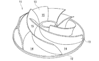
図1は、バンドを取り除いてランナベーンの入口側の斜め後方から見た本発明に係る水力機械のランナを示す斜視図である。なお、ランナは、説明の便宜上、6枚のランナベーンを備えている。 FIG. 1 is a perspective view showing a runner of a hydraulic machine according to the present invention viewed from an oblique rear side on the inlet side of a runner vane with a band removed. Note that the runner is provided with six runner vanes for convenience of explanation.
本実施形態に係る水力機械のランナ11は、円盤状に形成されたクラウン12に、一体として固設され、外周側から内周側に向って曲線状に配置され、例えば6枚のランナベーン13を備え、外周側の入口14から内周側の出口15に向って水が流れ、その際、水の持つエネルギを動力(回転トルク)に換え、主軸(図示せず)に与えるようになっている。
The
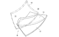
また、本実施形態に係る水力機械のランナ11は、図2に示すように、例えば1枚のランナベーン13の両側端のうち、一端側にバンド片16を製作一体として固設し、他端側にクラウン片17を製作一体として固設した分割ランナ片18を予め製作しておき、予め製作しておいた分割ランナ片18を、図1に示すように組み立てランナ11を構成する着脱自在な分割タイプになっている。
Moreover, as shown in FIG. 2, the
なお、分割ランナ片18に適用するランナベーン13は、プロファイル形状の異なる多種類のものが予め用意されている。
In addition, the
次に、水力機械のランナ製造方法を説明する。 Next, the runner manufacturing method of a hydraulic machine is demonstrated.
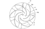
まず、例えば、CADシステムに、図3および図4に示すバンド片16、クラウン片17およびランナベーン片19a,19b等の形状を示すデータを予め記憶させておき、記憶させておいたデータの出力に基づいてNC工作機械のカッタを移動させて素材ブロックを切削加工し、分割ランナ片18を形成する。なお、分割ランナ片18の合わせ面は、図3に示すX−Y座標を基準に半径方向に向って延びる方向に形成している。
First, for example, in the CAD system, data indicating the shapes of the
このように、NC工作機械の切削加工により形成された分割ランナ片18は、図4に示すように、ランナベーン片19aのバンド片16およびクラウン片17と別のランナベーン19bのバンド片16およびクラウン片17との位置合わせを行い、例えばボルト等の固定手段23で固定される。
Thus, as shown in FIG. 4, the divided
このように形成された分割ランナ片18は、図3に示すように環状に組み立てられ、ボルト等の固定手段20で固定され、ランナ11として形成される。
The divided
このように、本実施形態は、素材ブロックをNC工作機械等で切削加工して分割ランナ片18を製作しておき、製作した分割ランナ片18を固定手段23で固定させる着脱自在な構造のランナ11に形成するので、取外し、取付けの作業時間をより一層短くすることができ、作業者の労力をより一層軽減することができる。
As described above, in the present embodiment, the
なお、本実施形態は、新設の実機ランナおよび模型用ランナについて説明したが、既設のランナを改造する場合、あるいは模型用ランナを改造する場合にも適用することができる。 In addition, although this embodiment demonstrated the newly installed actual machine runner and the model runner, it can be applied also when modifying the existing runner or when modifying the model runner.
従来、既設の水力機械のランナは、長年の使用の結果、ランナベーン等がキャビテーション等による壊食を受け水車効率が著しく低下することがある。また、部分負荷運転時の水車効率が製作当初に較べて低下する場合もある。さらに、模型を使ってデータを収集する場合、ランナベーンの異なったプロファイルを使用してデータを収集する場合がある。 Conventionally, runners of existing hydraulic machines may suffer from erosion due to cavitation or the like as a result of long-term use, and the turbine efficiency may be significantly reduced. In addition, the turbine efficiency during partial load operation may be lower than at the beginning of production. Furthermore, when collecting data using a model, data may be collected using different profiles of runner vanes.
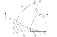
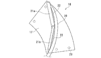
本実施形態は、このような点を考慮したもので、図5で示す分割ランナ片18のうち、実線で示す位置にあった既設のランナベーン片20をNC工作機械等で削り取り、削り取った位置に沿って素材ブロック21a,21bをクラウン片17にはんだ盛り溶接部22で固設する。
In the present embodiment, such a point is taken into consideration. Of the divided
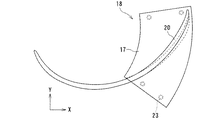
素材ブロック21a,21bをクラウン片17に固設後、本実施形態は、図6に示すように、ランナベーン片20を破線で示す既設の位置から実線で示す位置になる形状に切削加工する。そして、ランナベーン片20の切削加工が終了すると、分割ランナ片18は、隣りの分割ランナ片と固定手段23で互いを固定させる。なお、ランナベーン片20を支持するバンド片について説明していないが、クラウン片17と同様な手法で溶接施工、切削加工が行われる。
After the
なお、本実施形態は、素材ブロック21a,21bをクラウン片17およびバンド片16のそれぞれにはんだ盛り溶接部22で固設したが、この例に限らず、例えばランナベーン片を樹脂製にし、光造形により製作してもよい。
In the present embodiment, the
このように本発明に係る水力機械のランナ、水力機械のランナ製造方法および水力機械は、バンド、クラウン、ランナベーンで構成されるランナを、予め幾つかに区分けした分割ランナ片として作成し、各分割ランナ片を固定手段で固定する、いわゆる着脱自在なランナとして構成するので、新設の際、あるいは旧設のものを一部新設に交換する際、その作業時間をより一層短かくすることができ、作業者の労力をより一層軽減させることができる。 As described above, the hydraulic machine runner, the hydraulic machine runner manufacturing method, and the hydraulic machine according to the present invention create a runner composed of a band, a crown, and a runner vane as divided runner pieces divided into several parts in advance. Since it is configured as a so-called detachable runner that fixes the runner piece with a fixing means, the work time can be further shortened when newly installing or replacing part of the old one with a new one. The labor of the worker can be further reduced.
1 主軸
2 ランナ
3 ケーシング
4 ステーベーン
5 ガイドベーン
6 上カバー
7 下カバー
8 吸出し管
9 ランナベーン
11 ランナ
12 クラウン
13 ランナベーン
14 入口
15 出口
16 バンド片
17 クラウン片
18 分割ランナ片
19a,19b ランナベーン片
20 ランナベーン片
21a,21b 素材ブロック
22 はんだ盛り溶接部
23 固定手段
1
Claims (3)
Priority Applications (1)
| Application Number | Priority Date | Filing Date | Title |
|---|---|---|---|
| JP2004108313A JP2005291114A (en) | 2004-03-31 | 2004-03-31 | Hydraulic machine runner, hydraulic machine runner manufacturing method and hydraulic machine |
Applications Claiming Priority (1)
| Application Number | Priority Date | Filing Date | Title |
|---|---|---|---|
| JP2004108313A JP2005291114A (en) | 2004-03-31 | 2004-03-31 | Hydraulic machine runner, hydraulic machine runner manufacturing method and hydraulic machine |
Publications (1)
| Publication Number | Publication Date |
|---|---|
| JP2005291114A true JP2005291114A (en) | 2005-10-20 |
Family
ID=35324323
Family Applications (1)
| Application Number | Title | Priority Date | Filing Date |
|---|---|---|---|
| JP2004108313A Pending JP2005291114A (en) | 2004-03-31 | 2004-03-31 | Hydraulic machine runner, hydraulic machine runner manufacturing method and hydraulic machine |
Country Status (1)
| Country | Link |
|---|---|
| JP (1) | JP2005291114A (en) |
-
2004
- 2004-03-31 JP JP2004108313A patent/JP2005291114A/en active Pending
Similar Documents
| Publication | Publication Date | Title |
|---|---|---|
| AU2003236386B2 (en) | Improved method for production of a rotor of a centrifugal compressor | |
| US7761990B2 (en) | Method of repairing a stationary airfoil array directing three-dimensional flow | |
| CA2308062C (en) | A method for producing matched fluidic surfaces | |
| US8074866B2 (en) | Method or restoring turbine vane attachment systems in a turbine engine | |
| US20030138301A1 (en) | Method for milling fishbone-type notches | |
| CN103028917A (en) | Machining process for low-pressure first-stage stationary blades of gas turbines | |
| CN108942107A (en) | A kind of manufacturing method of impact type waterturbine wheel | |
| CN105108462B (en) | A kind of partition board of steam turbine full circle welding method | |
| CN105275865A (en) | Rotation part of rotary machine and method of manufacturing the same | |
| CN111545993B (en) | Manufacturing method of bucket blade in runner of impulse turbine | |
| CN201950298U (en) | Replaceable carbide blade hob | |
| EP2823149B1 (en) | Turbine diaphragm airfoil, diaphragm assembly, and method of repair | |
| JP2006348937A (en) | Turbine blade and method of manufacturing the same | |
| RU2749240C2 (en) | Method of manufacturing or repairing a part of a rotary machine, as well as a part manufactured or repaired using such a method | |
| CN202123260U (en) | Combined cutting tool for machining inner buckled type water band coupling | |
| JP2005291114A (en) | Hydraulic machine runner, hydraulic machine runner manufacturing method and hydraulic machine | |
| JP4924170B2 (en) | Hydraulic machine stay vanes | |
| US10914174B2 (en) | Method for the construction of bladed discs for radial turbomachines and a bladed disc obtained by means of this method | |
| KR100932395B1 (en) | Dismantling method of generator stator using lifting machine | |
| KR101418442B1 (en) | The method of manufacturing runner for cross flow water current turbine | |
| CN221322340U (en) | Rust removal shaping milling cone structure of oil-gas field sleeve | |
| EP3604793A1 (en) | Inter-blade profiles for hydraulic turbines with removable cover part | |
| JP2002310053A (en) | Runner of water turbine, manufacturing method for it, and water turbine | |
| CN217106915U (en) | Milling shoe | |
| KR102952144B1 (en) | Method for forming or repairing a part having a protruding section, and related turbomachinery part |