JP2005291083A - Turbine acceleration display manual activation device and manual activation method thereof - Google Patents
Turbine acceleration display manual activation device and manual activation method thereof Download PDFInfo
- Publication number
- JP2005291083A JP2005291083A JP2004106810A JP2004106810A JP2005291083A JP 2005291083 A JP2005291083 A JP 2005291083A JP 2004106810 A JP2004106810 A JP 2004106810A JP 2004106810 A JP2004106810 A JP 2004106810A JP 2005291083 A JP2005291083 A JP 2005291083A
- Authority
- JP
- Japan
- Prior art keywords
- turbine
- acceleration
- rotational speed
- schedule
- rotation
- Prior art date
- Legal status (The legal status is an assumption and is not a legal conclusion. Google has not performed a legal analysis and makes no representation as to the accuracy of the status listed.)
- Pending
Links
Images
Landscapes
- Control Of Turbines (AREA)
Abstract
【課題】タービンの手動起動において、タービンの回転数の制御をより容易に行うための加速度表示手動起動装置及び方法を提供する。
【解決手段】回転センサ17bの回転信号を受けて、タービンを自動制御起動するTSC制御手段11と、TSC動制御手段の自動制御出力を停止し、監視操作盤手段15から起動を手動操作により行う切換手段と、切換手段の作動後にタービン実回転速度を算出し、設定された起動運転プランのスケジュール回転速度及びスケジュール加速度を読込み、これ等を比較、判定し、その結果に基づいて手動により設定すべき目標加速度を監視操作盤手段へ出力するTMS起動制御手段12と、目標加速度と、タービンの現況の加速度とを対比して表示する指示計手段14と、この指示計手段を監視する運転員が、タービンに注入する蒸気量或いはガス量を遠隔手動で操作するスイッチ手段16とからなるタービン加速度表示手動起動装置。
【選択図】図1An acceleration display manual activation device and method for easily controlling the rotational speed of a turbine in manual activation of the turbine.
Upon receipt of a rotation signal from a rotation sensor 17b, the TSC control means 11 for automatically controlling and starting the turbine and the automatic control output of the TSC motion control means are stopped, and the start from the monitoring operation panel means 15 is performed manually. After the switching means and the switching means are operated, the actual turbine rotation speed is calculated, the schedule rotation speed and the schedule acceleration of the set start-up operation plan are read, these are compared, determined, and manually set based on the result. The TMS activation control means 12 for outputting the target acceleration to the monitoring operation panel means, the indicator means 14 for comparing and displaying the target acceleration and the current acceleration of the turbine, and the operator who monitors the indicator means A turbine acceleration display manual activation device comprising switch means 16 for remotely and manually operating the amount of steam or gas injected into the turbine.
[Selection] Figure 1
Description
本発明は、プロセス制御用計算機システムによるタービンの運転に関し、特にタービンの自動起動制御が不調時に、運転員が行う手動による起動運転を支援する運転加速度表示システムに関する。 The present invention relates to operation of a turbine by a process control computer system, and more particularly to an operation acceleration display system that supports manual start-up operation performed by an operator when automatic start-up control of the turbine is malfunctioning.
プラントなどを制御するプロセス制御用計算機システムにおいて、タービンの起動制御には、TSM(Turbine Start up Monitor)モードと呼ばれるタービン起動監視モードと、TSC(Turbine Start up Controller)モードと呼ばれるタービン起動制御モードがある。 In a process control computer system for controlling a plant or the like, turbine start-up control includes a turbine start-up monitoring mode called TSM (Turbine Start up Monitor) mode and a turbine start-up control mode called TSC (Turbine Start up Controller) mode. is there.
通常のタービンの起動では、プロセス制御用計算機システムの専用制御装置であるTSC制御装置により、TSCモードで自動制御が行われて起動される。このTSCモードによる起動では、タービンの作動状況が逐次検出されて、シーケンス/フィードバックが行われる。これにより、所定の定格運転状態まで、例えば発電プラントのタービンに供給される蒸気のバルブの開閉が自動調整される。この自動調整により、タービンの回転数は所定のパターンで徐々に上昇して、定常の定格運転に移行する。 In normal turbine startup, automatic control is performed in the TSC mode by a TSC controller that is a dedicated controller of the process control computer system. In the start-up in the TSC mode, the operation state of the turbine is sequentially detected, and sequence / feedback is performed. Thereby, the opening and closing of the valve of the steam supplied to, for example, the turbine of the power plant is automatically adjusted until a predetermined rated operation state. By this automatic adjustment, the rotational speed of the turbine gradually increases in a predetermined pattern and shifts to a steady rated operation.
一方、このTSC制御の不調時、或いは何等かの原因によるプロセス制御用計算機システムの部分的な不調時には、TMSモードに切換えられて、監視操作盤の計器やモニタの表示或いは指示の内容を判断して、運転員が運転ハンドルまたはスイッチの操作、或いは設定データ入力などを行って手動操作による起動が行われる。しかし、この不調時には、タービンの運転状況に関して、タービンに取り付けられた回転センサにより検知されたタービン回転速度(回転数)、及びこの回転速度がTSC制御装置で処理されて、現状の加速度に対し、所定のタービン回転速度を得るための、自動制御におけるその増減指示である加速度指令値が、TSC制御装置から出力され、指示計には加速度の現況が表示されるのみである。 On the other hand, when the TSC control malfunctions or when the process control computer system malfunctions due to any cause, it is switched to the TMS mode, and the contents of the monitor or monitor display or instruction are judged. Then, the operator operates the operation handle or the switch, or inputs setting data to start up by manual operation. However, during this malfunction, the turbine rotation speed (number of rotations) detected by the rotation sensor attached to the turbine and the rotation speed are processed by the TSC controller with respect to the current acceleration. An acceleration command value, which is an increase / decrease instruction in automatic control, for obtaining a predetermined turbine rotation speed is output from the TSC controller, and the current state of acceleration is only displayed on the indicator.
TSMモードによるタービンの起動を行うときには、起動回転速度(回転数)パターン、すなわち所定のタイムスケジュールで、ラブチェック(回転翼接触などの異常チェック)、定速保持(タービン熱応力除去の回転速度保持)などのタービン回転速度の制御シーケンスを、タービンの運転の安全及び安定ために実行する必要がある。タイムスケジュールに沿った正確な起動運転を行うためには、従来のプロセス制御システムの指示計に表示される回転速度、或いは加速度指令の結果の加速度値では、手動操作による制御が困難であるという問題があった。 When the turbine is started in TSM mode, the start rotation speed (rotation speed) pattern, that is, a predetermined time schedule, love check (abnormality check such as rotor blade contact), constant speed maintenance (rotation speed maintenance for turbine thermal stress removal) A control sequence of the turbine rotation speed such as) must be executed for the safety and stability of the turbine operation. In order to perform an accurate start-up operation according to the time schedule, it is difficult to control manually by the rotation speed displayed on the indicator of the conventional process control system or the acceleration value as a result of the acceleration command. was there.
特に昇速中(回転数上昇中)の加速度(昇速率)の過度の設定はタービン損傷、破壊に繋がり、適切な回転速度になる操作、運転が安全かつ安定なタービンの運転に重要な制御対象である。しかし、運転員の行う操作は、タービンへの例えば蒸気量を制御するバルブの開閉操作であり、このバルブの開閉によりタービン回転の加速度が変化し、この加速度の積分値が回転数の上昇となる。したがって、運転員の手動操作によるタービン運転、制御には、目標加速度値の表示・周知が、不可欠である。 In particular, excessive acceleration (acceleration rate) setting during acceleration (during rotation speed) will lead to turbine damage and destruction, and will be an important control target for operation to achieve an appropriate rotation speed and safe and stable operation of the turbine. It is. However, the operation performed by the operator is, for example, an opening / closing operation of a valve for controlling the amount of steam to the turbine. The acceleration of the turbine rotation is changed by opening / closing the valve, and the integral value of the acceleration increases the rotation speed. . Therefore, displaying and notifying the target acceleration value is indispensable for turbine operation and control by manual operation of the operator.
本発明は上記のような従来の問題点に鑑みてなされたもので、タービン起動時における運転員による手動操作の昇速のために、タービン運転の目標加速度を指示計に出力し、タービンの回転数の制御をより容易に行うことのできるTSMモード加速度指示を出力するタービン加速度表示手動起動装置、及びその方法を提供することを目的とする。 The present invention has been made in view of the above-described conventional problems, and outputs a target acceleration of turbine operation to an indicator for speeding up manual operation by an operator at the time of turbine startup, and rotation of the turbine. It is an object of the present invention to provide a turbine acceleration display manual activation device that outputs a TSM mode acceleration instruction and a method thereof that can more easily control the number.
本発明のタービン加速度表示手動起動装置は、タービンの運転を行うプロセス制御装置に備えられ、前記タービンからの回転作動信号を受けて、前記タービンの起動を自動制御するタービン起動自動制御手段と、前記タービンの作動状況を表示し、前記プロセス制御装置を操作する監視操作盤手段と、このタービン起動自動制御手段の自動制御出力を停止し、前記監視操作盤手段から前記タービンの起動を手動操作により行う切換手段と、前記手動操作に切換えた起動を行う場合に、タービンの起動開始後の各ステップにおける回転速度及び加速度を起動運転プランとして、前記タービンの状況に基づき作成、設定する起動スケジュールサーバ手段と、前記切換手段の作動後に、前記タービン或いは前記タービン起動自動制御手段からの回転作動信号により実回転速度を算出し、設定された前記起動運転プランのスケジュール回転速度及びスケジュール加速度を読込み、起動開始後の各ステップにおいてこれ等を比較、判定し、その結果に基づいて手動により設定すべき目標加速度として、これを前記監視操作盤手段へ出力するタービン手動起動制御手段と、このタービン手動起動制御手段から出力された前記目標加速度と、前記タービンの現況の加速度とを対比して表示する前記監視操作盤手段に備えた指示計手段と、この指示計手段を監視する運転員が、前記タービンに注入する蒸気量或いはガス量を遠隔手動で操作するスイッチ手段とからなることを特徴とするものである。 A turbine acceleration display manual activation device according to the present invention is provided in a process control device for operating a turbine, receives a rotation operation signal from the turbine, and automatically controls the turbine activation, and the turbine activation automatic control means, Monitoring operation panel means for displaying the operating status of the turbine and operating the process control device and automatic control output of the turbine activation automatic control means are stopped, and the turbine is started from the monitoring operation panel means by manual operation. A switching means, and a startup schedule server means for creating and setting the rotational speed and acceleration in each step after the start of the turbine startup as a startup operation plan based on the state of the turbine when the startup is switched to the manual operation. , After the operation of the switching means, the rotation from the turbine or the turbine start automatic control means Calculate the actual rotation speed from the motion signal, read the schedule rotation speed and schedule acceleration of the set start-up operation plan, compare and determine these at each step after start-up, and set manually based on the result Turbine manual start control means for outputting the target acceleration to the monitoring operation panel means, the target acceleration output from the turbine manual start control means, and the current acceleration of the turbine for comparison. The indicator means means provided in the monitoring operation panel means, and an operator who monitors the indicator means means comprises a switch means for remotely operating manually the amount of steam or gas injected into the turbine. To do.
さらに、タービン加速度表示手動起動装置の起動スケジュールサーバ手段が作成、設定する起動運転プランは、前記タービンの温度、負荷(予定出力)、注入する蒸気或いはガスの温度及び圧力に基づき、ラブチェック(異常チェック)及び1回以上の定速保持(熱応力除去)を含む昇速プランであることを特徴とするものである。 Furthermore, the start-up operation plan created and set by the start-up schedule server means of the turbine acceleration display manual start-up device is based on the temperature, load (scheduled output) of the turbine, and the temperature and pressure of the steam or gas to be injected. Check) and a speed-up plan including one or more constant-speed holding (removal of thermal stress).
さらに、タービン加速度表示手動起動装置のタービン手動起動制御手段が出力する目標加速度は、加速度指示の計算タイミングで無い場合、及びタービンの回転が停止している場合、及びタービンの回転数保持中の場合、及びタービンの実回転速度が前記起動運転プランに設定している目標回転速度との所定の許容差範囲を越えて大きい場合には、加速度0rpm2であり、タービンの実回転速度が前記起動運転プランに設定しているスケジュール回転速度との所定の許容差範囲内の場合、及び所定の許容差範囲外で、所定の演算式により算出した加速度値が前記スケジュール加速度より小さい場合には、前記起動運転プランに設定しているスケジュール加速度値であり、前記所定の許容差範囲外で、所定の演算式により算出した加速度値が前記スケジュール加速度より大きい場合には、前記算出した加速度値あり、前記ラブチェック中の場合で、バルブが全閉され、所定のタービン回転速度に達したブレークポイント経過後では、所定の負の加速度値であることを特徴とするものである。 Further, the target acceleration output from the turbine manual activation control means of the turbine acceleration display manual activation device is not at the calculation timing of the acceleration instruction, the rotation of the turbine is stopped, and the turbine rotation speed is being maintained. , And when the actual rotational speed of the turbine is larger than a predetermined tolerance range with the target rotational speed set in the start-up operation plan, the acceleration is 0 rpm 2 , and the actual rotational speed of the turbine is the start-up operation. If the acceleration value calculated by a predetermined arithmetic expression is smaller than the scheduled acceleration when it is within a predetermined tolerance range with the schedule rotation speed set in the plan and outside the predetermined tolerance range, the activation It is a schedule acceleration value set in the driving plan, and the acceleration value calculated by a predetermined arithmetic expression outside the predetermined tolerance range is When the acceleration is larger than the scheduled acceleration, the calculated acceleration value is present. During the love check, the valve is fully closed, and after a break point has reached a predetermined turbine rotational speed, a predetermined negative acceleration value is obtained. It is characterized by being.
また、本発明のタービン加速度表示手動起動方法は、タービンの運転を行うプロセス制御装置に備えられ、前記タービンからの回転作動信号を受けて、前記タービンの起動を自動制御するタービン起動自動制御手段の作動/非作動を選択するモード選択ステップと、このモード選択ステップで作動を選択した場合に、前記タービン起動自動制御手段による前記タービンの自動制御起動を行う自動制御起動ステップと、前記モード選択ステップで非作動を選択した場合に、前記タービンを手動操作起動するため、前記タービンの状況に基づき、ラブチェック(異常チェック)及び1回以上の定速保持(熱応力除去)を含む、回転速度及び加速度の起動運転プランを作成、設定する起動スケジュール設定ステップと、作成、設定された前記起動運転プランの回転速度及び加速度を読込んで前記タービンの起動を開始するタービン起動開始ステップと、起動開始後の前記タービンの実回転速度をタービンに設けた回転センサからの回転信号により算出する実回転速度計測ステップと、この実回転速度計測ステップで得た実回転速度と、読込んだ前記起動運転プランのスケジュール回転速度及びスケジュール加速度とを比較、判定し、回転速度保持の加速度ゼロ、及びラブチェックの負の加速度を含む前記起動運転プランに予め設定されたスケジュール加速度、或いは前記実回転速度と前記スケジュール回転速度との差による所定の演算式で
算出した加速度のいずれかを指示加速度として設定する加速度指示ステップと、この加速度指示ステップで設定した指示加速度を目標加速度とし、前記実回転速度から算出した実加速度とし、これらの加速度を前記プロセス制御装置の監視操作盤手段の指示計に共に表示する指示計表示ステップとからなることを特徴とし、この指示計の表示を監視する運動員が、前記タービンの蒸気或いはガスの注入バルブの開閉操作を手動で行いタービンの起動する方法である。
A turbine acceleration display manual activation method according to the present invention is provided in a process control device for operating a turbine, and includes a turbine activation automatic control means for automatically controlling the activation of the turbine in response to a rotation operation signal from the turbine. A mode selection step for selecting operation / non-operation, an automatic control start step for performing automatic control start of the turbine by the turbine start automatic control means when an operation is selected in the mode selection step, and a mode selection step. Rotation speed and acceleration, including love check (abnormality check) and one or more constant speed maintenance (removal of thermal stress), based on the state of the turbine to manually start the turbine when non-operation is selected A startup schedule setting step for creating and setting a startup operation plan for the startup operation, and the startup operation that has been created and set A turbine startup start step for reading the plan rotational speed and acceleration to start the turbine, and an actual rotational speed measurement for calculating the actual rotational speed of the turbine after the startup based on a rotation signal from a rotation sensor provided in the turbine. The actual rotational speed obtained in this step and the actual rotational speed measuring step is compared with the schedule rotational speed and schedule acceleration of the read start-up operation plan, and judged to be zero. An acceleration instruction step for setting, as an instruction acceleration, either a schedule acceleration set in advance in the start-up operation plan including the acceleration or an acceleration calculated by a predetermined arithmetic expression based on a difference between the actual rotation speed and the schedule rotation speed And the target acceleration set in this acceleration command step as the target acceleration, It comprises an indicator display step for displaying actual accelerations calculated from actual rotational speeds and displaying these accelerations together on an indicator of the monitoring operation panel means of the process control device, and monitoring the display of the indicator In this method, the athlete starts the turbine by manually opening and closing the steam or gas injection valve of the turbine.
さらに、タービン加速度表示手動起動方法の前記加速度指示ステップは、加速度指示の計算タイミングで無い場合、及びタービンの回転が停止している場合、及びタービンの回転数保持中の場合、及びタービンの実回転速度が前記起動運転プランに設定している目標回転速度との所定の許容差範囲を越えて大きい場合には、加速度を0rpm2とするゼロ加速度指示ステップと、タービンの実回転速度が前記起動運転プランに設定しているスケジュール回転速度との所定の許容差範囲内の場合、及び所定の許容差範囲外で、所定の演算式により算出した加速度値が前記スケジュール加速度より小さい場合には、加速度を前記起動運転プランに設定しているスケジュール加速度値とするスケジュール加速度指示ステップと、前記所定の許容差範囲外で、所定の演算式により算出した加速度値が前記スケジュール加速度より大きい場合には、加速度を前記算出した加速度値とする算出加速度指示ステップと、前記ラブチェック中の場合で、バルブが全閉され、所定のタービン回転速度に達したブレークポイント経過後では、加速度を所定の負の加速度値とする減速加速度指示ステップとが含まれてなることを特徴とする手動で起動する方法である。 Further, the acceleration instruction step of the turbine acceleration display manual activation method includes the case where the calculation timing of the acceleration instruction is not reached, the case where the rotation of the turbine is stopped, the case where the rotation speed of the turbine is being maintained, and the actual rotation of the turbine. When the speed is larger than a predetermined tolerance range with respect to the target rotational speed set in the start-up operation plan, the zero acceleration instruction step for setting the acceleration to 0 rpm 2 and the actual rotational speed of the turbine are the start-up operation. If it is within a predetermined tolerance range with the schedule rotation speed set in the plan, and if it is outside the predetermined tolerance range and the acceleration value calculated by a predetermined arithmetic expression is smaller than the schedule acceleration, the acceleration is Schedule acceleration instruction step for setting a schedule acceleration value set in the start-up operation plan, and out of the predetermined tolerance range In the case where the acceleration value calculated by a predetermined arithmetic expression is larger than the scheduled acceleration, the valve is fully closed in the calculation acceleration instruction step in which the acceleration is the calculated acceleration value and in the case of the love check, A manual start-up method is characterized by including a deceleration acceleration instruction step in which the acceleration is set to a predetermined negative acceleration value after the break point has reached a predetermined turbine rotation speed.
本発明のタービン手動起動運転加速度表示装置、及びその方法は、プロセス制御計算機システムで運転が行われるプラントのタービン起動において、タービン起動監視(TMS)モードによる手動起動が行われる場合に、適切な加速度指示を指示計に表示できるための、運転員の手動操作が、煩雑でなく容易に行なえ、タービンの起動時の状況に対応して設定される起動スケジュールに沿った、安全でかつ安定なタービンの起動が実施できる効果がある。 The turbine manual start-up operation acceleration display device and method of the present invention provide an appropriate acceleration when manual start-up in the turbine start-up monitoring (TMS) mode is performed in the turbine start-up of a plant operated by a process control computer system. It is possible to display the instructions on the indicator, so that the operator's manual operation can be performed easily and without any trouble, and a safe and stable turbine that meets the start-up schedule set according to the start-up situation of the turbine. There is an effect that can be activated.
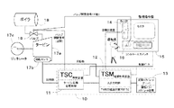
図1は、本発明のタービン加速度表示手動起動装置の一実施形態を示す構成ブロック図で、例えば、発電プラントにおける蒸気タービンを起動する例である。 FIG. 1 is a configuration block diagram showing an embodiment of a turbine acceleration display manual starter according to the present invention, and is an example of starting a steam turbine in a power plant, for example.
図1に示す発電プラントの概略の構成は、タービン手動起動運転・加速度表示装置を含むこのプラントの制御を行うプロセス制御装置10と、プラントの入出力の表示及び操作を行う監視操作盤15と、ボイラ18からの蒸気により制御対象のタービン17aが駆動されて、発電を行う蒸気タービン発電機17とからなる。
The schematic configuration of the power plant shown in FIG. 1 includes a
さらに構成の詳細は、このプロセス制御装置10が、自動制御によりタービン起動を行うTSC制御装置11と、運転員の手動操作によるタービン起動を支援、制御するTSM起動装置12と、このTSM起動装置12に接続されて起動時の運転スケジュールを計算、設定する自動化サーバ13と、図示していない通常の運転の制御を行うタービン自動制御装置(プロセス制御コンピュータ)とから構成される。また、監視操作盤15には、加速度表示計14或いはタービン回転数表示計などのプロセス運転状況を表示する計器、プロセスの進行状況やプロセス装置の運転状況全容を表示するモニター装置、及び操作を入力するコントロールスイッチ16やキーボードなどを備えている。
Further, for details of the configuration, the
一方、制御や操作の対象となる蒸気タービン発電機17には、ボイラ18からの蒸気が、バルブ19を経由してタービン17aに供給され、回転軸を共にする発電機17cが回転し、発電が行われる。タービン17aには、回転センサ17bが備えられてタービンの作動状況がプロセス制御装置に入力される。なお、バルブ19は、プロセス制御装置10或いは監視操作盤15により、開閉の操作が行われて、タービンの運転状態を制御調整する。
On the other hand, steam from the
本実施形態における作用、動作を、以下に図を用いて説明する。 The operation and operation of this embodiment will be described below with reference to the drawings.
本実施形態における所謂プロセス制御コンピュータ(図示せず)による自動制御起動では、TSC制御装置11が、タービン17aの回転センサ17bから入力される回転数信号により、回転速度(昇速)を計算し、加速度指令値を指示する。この加速度指令値に基づくバルブ19の開閉が行われて、ラブチェックを含む数段階に設定される回転速度の所定パターンを経て、タービン17aの定格回転数を保持する状態まで、起動運転がなされる。なお、このタービン17aを含むプラントの起動の状況は、タービン回転速度、加速度の現在値などが監視操作盤15に表示され、運転員が監視することができる。
In the automatic control activation by the so-called process control computer (not shown) in the present embodiment, the TSC controller 11 calculates the rotational speed (increased speed) from the rotational speed signal input from the
次に、運転員の手動操作によるタービン起動における本実施形態の作用、動作について、図2乃至4を用いて説明する。 Next, the operation and operation of the present embodiment in the turbine startup by the manual operation of the operator will be described with reference to FIGS.
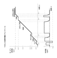
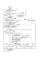
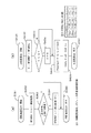
図2は、自動化サーバ13において算出されたTMSによる起動時のタービン起動運転プラン(回転速度スケジュール)の例を図示したものである。図3は、本実施形態のTSM起動制御装置12において実行されるTMS加速度計算プログラムによる目標加速度算出、表示のフロー図である。図4は、図3に示すフローにおけるタービン回転数サブルーチン及び加速度算出サブルーチンのフロー図である。
FIG. 2 illustrates an example of a turbine start-up operation plan (rotation speed schedule) at the time of start-up by TMS calculated in the
本実施形態の図1に示す例えば発電プラントにおける、運転員の手動によるタービン17aの起動は、図3に示すフローに従って、先ずステップS31の監視操作盤15の電源をオンとする。これにより、このプラントにおけるプロセス制御の対象となる各装置及び機器を作動可能状態にする。
For example, in the power plant shown in FIG. 1 of the present embodiment, the operator manually starts the
ここで、例えば、自動制御によるタービンの起動を望む場合は、監視操作盤15においてTSCモードの設定がされて、ステップS32の判定によりステップS33へ進む。ステップS33では、TSC制御装置11が正常であれば、回転センサ17b及びプロセス制御用コンピュータ(図示せず)とデータが取り交わされて、加速度指令値が出力されて、これに対応するバルブ19の開閉が行われる。さらにステップS34で、TSC制御装置11により計測されたタービン作動中の加速度が、加速度指示値(XACL)として設定されて、これをステップS48により監視操作盤15の加速度指示計14に目標加速度値として表示する。
Here, for example, when it is desired to start the turbine by automatic control, the TSC mode is set on the
次に、例えば、TSC制御装置の不調時、或いはメンテナンス後などのステップバイステップで行う試験運転等の場合に、運転員が手動でタービンを起動する場合は、監視操作盤15においてTSMモードの選択がなされる。この場合には、ステップS32で、ステップS35の「TSMモードによる手動起動が開始」に進む。
Next, when the operator starts the turbine manually, for example, when the TSC controller is malfunctioning or in a test operation performed step by step after maintenance, etc., the TSM mode is selected on the
ステップS35に進められた本プロセスは、次のステップS36において、TSMモードによる起動運転を開始して良いかを判定する。すなわち、表1の「S36」に示す判定事項「指示加速度計算開始タイミング」の4つの判定信号事項をチェックする。この4つの判定信号は、TSCモード運転とTSMモード運転を並列運転する設定でないこと、TSMモードが設定されていること、自動化サーバ13により、タービンの諸状況を踏まえたタービン起動運転プラン(回転速度スケジュール)が算定済みであること、さらに算定したタービン起動運転プランの各ブレークポイント(BP)を通過進行中であることの各条件であり、この4つの論理積が採られて、ステップS36の真/偽が判定される。ステップS36の論理積が、偽(N)の場合は、手動の操作を開始できる状況でないので、ステップS45に進み、加速度指示値(XACL)として「0rpm2」が設定されて、これをステップS48により監視操作盤15の加速度指示計14に目標加速度値として表示する。一方、ステップS36の論理積が、真(y)の場合は、手動起動運転を開始できる、或いは手動起動操作中であり、ステップS37へ進む。
ステップS37では、自動化サーバ13により予めタービンの温度、負荷(予定出力)等の諸状況を踏まえて算定、計画している図2に示すタービン起動運転プラン(回転速度スケジュール)に対し、TSM起動制御装置12が把握している手動起動の経過時点或いは通過ブレークポイント(BP)を参照して、スケジュールに設定されている加速度値を読み出して、これをスケジュール加速度値(PSCHCAL=SCHACL)として設定し、次のステップS38へ進める。なお、この設定、表1の「S37」に示される各昇速率信号の組合せにより設定される。
In step S37, the TSM start control is performed on the turbine start-up operation plan (rotational speed schedule) shown in FIG. 2 that is calculated and planned in advance by the
次のステップS38では、サブルーチン「タービン回転数」が実施されて、タービンの実回転数(回転速度)と、自動化サーバ13により算出されているタービン起動運転プランに計画されている目標回転数とを、検出或いは参照する。
In the next step S38, the subroutine “turbine rotational speed” is executed, and the actual rotational speed (rotational speed) of the turbine and the target rotational speed planned in the turbine start-up operation plan calculated by the
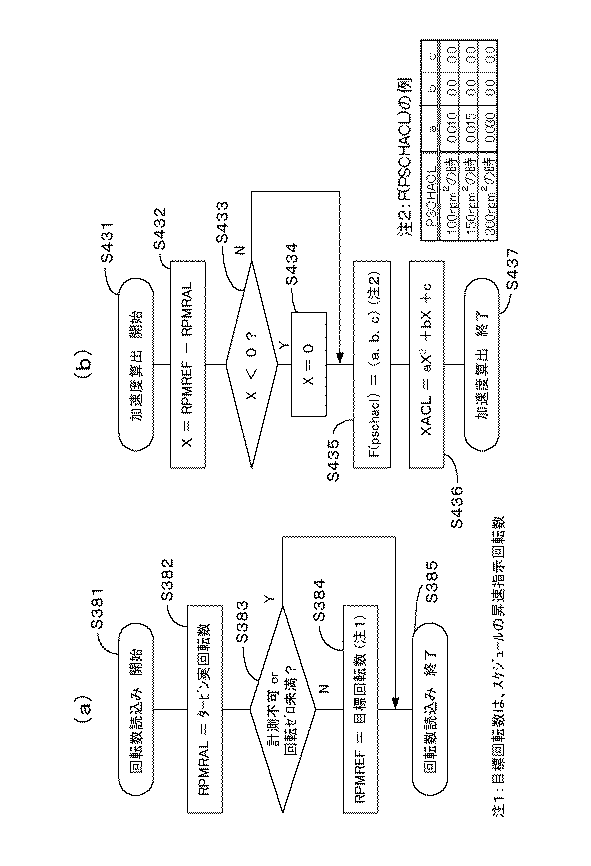
このステップS38で実施されるサブルーチン「タービン回転数」のフロー図を図4(a)に示す。このサブルーチンでは、ステップS381でサブルーチン「タービン回転数」が開始され、先ずステップS382で、タービン17aに取り付けられている回転センサ17bからの回転数信号により、タービンの実回転数を計測し、データ「RPMRAL」に書き込む。次にステップS383で、回転センサ17bの故障などによる計測不可或いはゼロ回転未満のデータになっていないかの真/偽が判定される。このステップS383の判定で、計測不可など(真)と判定された場合は、このサブルーチンを終了するステップS385へ進む。一方、ステップS385で正常な計測作動(偽)の判定した場合は、次のステップS384で、先に自動化サーバ13が算出設定しているタービン起動運転プランにおいてその時相に計画されている目標回転数を読み出して、データ「RPMREF」に書き込み、その後ステップS385で、サブルーチン「タービン回転数」を終了する。
FIG. 4A shows a flowchart of the subroutine “turbine speed” executed in step S38. In this subroutine, the subroutine “turbine rotational speed” is started in step S381, and first, in step S382, the actual rotational speed of the turbine is measured based on the rotational speed signal from the
ステップS38のサブルーチンの後、ステップS39により、タービンの回転の有無が判定される。この判定で回転が無い(偽)場合は、ステップS45へ進み、目標化速度値「XACL」の設定を「XACL=0rpm2」とし、停止を維持する。一方、回転が有る(真)と判定された場合は、ラブチェック運転中か、或いはその他の昇速運転中かを判定するために、ステップS40へ進める。 After the subroutine of step S38, whether or not the turbine is rotating is determined in step S39. If there is no rotation (false) in this determination, the process proceeds to step S45 where the target speed value “XACL” is set to “XACL = 0 rpm 2 ” and the stop is maintained. On the other hand, when it is determined that there is rotation (true), the process proceeds to step S40 in order to determine whether the love check operation is being performed or another speed-up operation is being performed.
ステップS40では、表1の「S40」に示す判定事項「主蒸気バルブ操作」の3つの判定信号事項「ラブチェック・ブレーク・ポイント進行中」、「MSVバルブ全閉」、「MSVバルブ開き始め数mm前」をチェックする。この3つの判定事項の真・真・偽の論理積が採られて、ステップS40の真/偽が判定される。ステップS40の論理積が、真(Y)の場合は、ラブチェックにおける負加速度の減速を行う時相になったことを示すので、ステップS47へ進み、目標化速度値「XACL」の設定を「XACL=−100rpm2」とする。この加速度の設定は、ステップS48により監視操作盤15の加速度指示計14に目標加速度値として表示するので、運転員はこの表示の指示に従って、タービンの実加速度がこの目標化速度になるようにコントロールスイッチ16を運転操作し、ラブチェックの負加速度の減速運転を実施する。
In step S40, the three determination signal items “LOVE CHECK / BREAK POINT IN PROGRESS”, “MSV valve fully closed”, “MSV valve opening start count” for the determination item “main steam valve operation” shown in “S40” of Table 1 Check "mm ago". The logical product of true, true, and false of these three determination items is taken, and true / false of step S40 is determined. If the logical product of step S40 is true (Y), it indicates that the time phase for negative acceleration deceleration in the love check has been reached, so the process proceeds to step S47, where the target speed value “XACL” is set to “ XACL = −100 rpm 2 ”. This acceleration setting is displayed as a target acceleration value on the
一方、ステップS40で偽(N)と判定されと、ステップS41で、タービン17aの実回転数(RPMRAL)が、予め算出、設定されているタービン起動運転プラン(回転速度スケジュール)の対応する時相における目標回転数(RPMREF)前後の回転数(式1に示される範囲)となっているか、判定される。
On the other hand, if it is determined to be false (N) in step S40, in step S41, the actual rotational speed (RPMMAL) of the
RPMREF−100<RPMRAL(実回転数)<RPMREF+50 (式1)
ステップS41の判定で、式1に示す範囲内(真(Y))であれば、ステップS42に進める。
RPMREF-100 <RPMRAL (actual rotation speed) <RPMREF + 50 (Formula 1)
If it is determined in step S41 that the value is within the range shown in Formula 1 (true (Y)), the process proceeds to step S42.
このステップS42では、タービンの起動運転の時相が、「回転数保持中」の時相であるか否かが判定されて、「回転数保持中」であれば、さらにステップS45に進めて、目標加速度(XACL)を0rpm2に設定し、ステップS48でこの目標加速度を表示、指示する。 In this step S42, it is determined whether or not the time phase of the start-up operation of the turbine is the time phase of “maintaining the rotational speed”, and if it is “maintaining the rotational speed”, the process further proceeds to step S45, The target acceleration (XACL) is set to 0 rpm2, and this target acceleration is displayed and instructed in step S48.
また、ステップS42で「回転数保持中」でない(タービンの昇速中)と判定すれば、ステップS46に進み、同じくタービン起動運転プランに計画され、先のステップS37で読込み設定したスケジュール加速度値(PSCHCAL=SCHACL)を目標加速度として設定し、ステップS48でこの目標加速度を表示、指示されて、運転員がタービンの昇速を維持する操作、運転を行う。 If it is determined in step S42 that the engine is not “rotating speed” (turbine speed increasing), the process proceeds to step S46, and the schedule acceleration value (similarly planned in the turbine start-up operation plan and read and set in the previous step S37). PSCHCAL = SCHACL) is set as the target acceleration, and the target acceleration is displayed and instructed in step S48, and the operator performs an operation and operation for maintaining the turbine acceleration.
一方、先のステップS41の判定で、式1に示す範囲外(偽(N))であれば、ステップS43の適切な加速度を算出するサブルーチン「加速度算出」が実施されて、タービン起動運転プランに計画されたタービン状況の起動に戻す加速度の修正値を目標加速度とする。 On the other hand, if the determination at the previous step S41 is outside the range shown in Equation 1 (false (N)), a subroutine “acceleration calculation” for calculating an appropriate acceleration at step S43 is executed, and the turbine startup operation plan is included. The corrected value of acceleration returned to the start of the planned turbine status is set as the target acceleration.
ステップS43で行うサブルーチン「加速度算出」のフロー図を図4(b)に示す。このサブルーチンでは、ステップS431でサブルーチン「加速度算出」が開始され、先ずステップS432で、タービンの実回転数(RPMRAL)と目標回転数(RPMREF)との差のずれ回転数Xを式2で算出する。
FIG. 4B shows a flowchart of the subroutine “acceleration calculation” performed in step S43. In this subroutine, the subroutine “acceleration calculation” is started in step S431. First, in step S432, the deviation rotational speed X of the difference between the actual rotational speed (RPMMAL) of the turbine and the target rotational speed (RPMREF) is calculated by the
X=PMREF(目標回転数)−RPMRAL(実回転数) (式2)
次に、ステップS433で、このずれ回転数Xが負数(真(Y))、すなわち実回転数が目標回転数を上回っているか、否かを判定する。このステップS433の判定で、真(Y)の場合は、実回転数が目標回転数を上回って、操作している加速度が過多であるので、次のステップS434によりずれ回転数XをX=0と置換え、ステップS435へ進む。一方、ずれ回転数Xが正値となり判定が偽(N)の場合は、実回転数が目標回転数に達していないので、ずれ回転数Xは保持してそのまま加速度値を補正するステップS435へ進める。
X = PMREF (target rotational speed) −RPMRAL (actual rotational speed) (Formula 2)
Next, in step S433, it is determined whether or not the deviation rotational speed X is a negative number (true (Y)), that is, whether the actual rotational speed exceeds the target rotational speed. If the determination in step S433 is true (Y), the actual rotational speed exceeds the target rotational speed and the operating acceleration is excessive, so that the shifted rotational speed X is set to X = 0 in the next step S434. And the process proceeds to step S435. On the other hand, if the rotational speed X is a positive value and the determination is false (N), the actual rotational speed has not reached the target rotational speed, so the rotational speed X is maintained and the acceleration value is corrected as it is. Proceed.
ステップS435において、先のスケジュールS37で設定したスケジュール加速度値(PSCHCAL)に対応する加速度算出式(式3)の係数a、b、cのセットを読み出す。ステップS436で、読み出した係数を適用して式3の補正の目標加速度(XACL)を算出する。なお、係数a、b、cは、対象となるタービンの運転特性により設計に置いて決定される数値であり、図示したものは1例を示してある。 In step S435, a set of coefficients a, b, and c of the acceleration calculation formula (formula 3) corresponding to the schedule acceleration value (PSCHCAL) set in the previous schedule S37 is read. In step S436, the corrected target acceleration (XACL) of Equation 3 is calculated by applying the read coefficient. The coefficients a, b, and c are numerical values determined in the design according to the operation characteristics of the target turbine, and the example shown is an example.
XACL=aX2+bX+c (式3)
なお、実回転数が目標回転数を上回って、ステップS434でX=0と置換えている場合は、この算出結果はゼロ(XACL=0)となる。
XACL = aX 2 + bX + c (Formula 3)
If the actual rotational speed exceeds the target rotational speed and X = 0 is substituted in step S434, the calculation result is zero (XACL = 0).
補正の目標加速度(XACL)を算出し終えると、ステップS437で加速度算出のサブルーチンを終了し、次のステップS44に戻る。 When the calculation of the corrected target acceleration (XACL) is completed, the acceleration calculation subroutine is terminated in step S437, and the process returns to the next step S44.
ステップS44では、ステップS436で算出した目標加速度が、ステップS37で読込んでいるスケジュール加速度値(PSCHCAL)と比較、判定される。算出した目標加速度がスケジュール加速度より大きい場合(判定が真(Y))は、算出したXACL値が、次のステップS48で、目標加速度として表示、指示されて、運転員がタービンの昇速を維持する操作、運転を行う。一方、算出した目標加速度がスケジュール加速度より小さい場合(判定が偽(N))は、ステップS46に進め、目標加速度値(XACL)はスケジュール加速度値(PSCHCAL)と差換えられて、次のステップS48で、これが表示、指示されて、運転員がタービンの昇速を維持する操作、運転を行う。 In step S44, the target acceleration calculated in step S436 is compared with the schedule acceleration value (PSCHCAL) read in step S37 and determined. When the calculated target acceleration is larger than the schedule acceleration (determination is true (Y)), the calculated XACL value is displayed and instructed as the target acceleration in the next step S48, and the operator maintains the turbine acceleration. Perform operations and operations. On the other hand, when the calculated target acceleration is smaller than the schedule acceleration (determination is false (N)), the process proceeds to step S46, where the target acceleration value (XACL) is replaced with the schedule acceleration value (PSCHCAL), and in the next step S48. This is displayed and instructed, and the operator performs an operation and operation to maintain the turbine speed up.
以上のように、タービン起動の状況に対応する加速度が、ステップS48により監視操作盤15の加速度指示計14に目標加速度値として表示した後、スタートのステップS31に戻り、タービン起動のそれぞれの時相がステップS36でチェックされて、次の目標加速度の算出が繰り返され、所定の定格回転数に達する。定格回転数になると、ステップS42で、回転数保持中となり、目標加速度は0rpm2が設定されて、定格運転に移行し手動による起動が終了する。
As described above, after the acceleration corresponding to the turbine activation state is displayed as the target acceleration value on the
以上に説明したように、本実施形態によれば、タービンを手動で起動する場合に、予め設定されたラブチェックを含むタービン起動運転プラン(回転速度スケジュール)に沿った昇速パターンとなる加速度を、監視操作盤の表示計に目標加速度として表示できるので、運転員の起動運転の操作が容易となる効果がある。また、高温、高速で作動するタービンの性能、特性に基づいて設定されるタービン起動運転プランの正確な実施が可能となる操作を、本実施形態により行えるので、タービンの起動が、安全、かつ効率の良い安定に行える利点もある。 As described above, according to the present embodiment, when the turbine is started manually, the acceleration that becomes the acceleration pattern along the turbine startup operation plan (rotational speed schedule) including the preset love check is set. Since it can be displayed as the target acceleration on the display meter of the monitoring operation panel, there is an effect that the start-up operation of the operator becomes easy. In addition, since this embodiment can perform operations that enable accurate execution of a turbine start-up operation plan that is set based on the performance and characteristics of a turbine that operates at high temperature and high speed, the start-up of the turbine is safe and efficient. There is also an advantage that can be performed stably.
10・・・プロセス制御装置、
11・・・TSC制御装置、
12・・・TSM起動装置、
13・・・自動化サーバ、
14・・・加速度表示計、
15・・・監視操作盤、
16・・・コントロールスイッチ、
17・・・蒸気タービン発電機、
17a・・・タービン、
17b・・・回転センサ、
17c・・・ジェネレータ、
18・・・ボイラ、
19・・・バルブ。
10 ... Process control device,
11 ... TSC controller,
12 ... TSM activation device,
13 ... Automation server,
14: Accelerometer,
15: Monitoring operation panel,
16 ... Control switch,
17 ... steam turbine generator,
17a ... turbine,
17b ... rotation sensor,
17c ... Generator,
18 ... Boiler,
19 ... Valve.
Claims (5)
前記タービンの作動状況を表示し、前記プロセス制御装置を操作する監視操作盤手段と、
このタービン起動自動制御手段の自動制御出力を停止し、前記監視操作盤手段から前記タービンの起動を手動操作により行う切換手段と、
前記手動操作に切換えた起動を行う場合に、タービンの起動開始後の各ステップにおける回転速度及び加速度を起動運転プランとして、前記タービンの状況に基づき作成、設定する起動スケジュールサーバ手段と、
前記切換手段の作動後に、前記タービン或いは前記タービン起動自動制御手段からの回転作動信号により実回転速度を算出し、設定された前記起動運転プランのスケジュール回転速度及びスケジュール加速度を読込み、起動開始後の各ステップにおいてこれ等を比較、判定し、その結果に基づいて手動により設定すべき目標加速度として、これを前記監視操作盤手段へ出力するタービン手動起動制御手段と、
このタービン手動起動制御手段から出力された前記目標加速度と、前記タービンの現況の加速度とを対比して表示する前記監視操作盤手段に備えた指示計手段と、
この指示計手段を監視する運転員が、前記タービンに注入する蒸気量或いはガス量を遠隔手動で操作するスイッチ手段とからなることを特徴とするタービン加速度表示手動起動装置。 Turbine start automatic control means provided in a process control device for operating the turbine and receiving the rotation operation signal from the turbine to automatically control the start of the turbine;
Monitoring operation panel means for displaying the operating status of the turbine and operating the process control device;
Switching means for stopping the automatic control output of the turbine start automatic control means and manually starting the turbine from the monitoring operation panel means,
When performing startup switched to the manual operation, a startup schedule server means for creating and setting the rotational speed and acceleration in each step after starting the turbine as a startup operation plan based on the status of the turbine;
After the operation of the switching means, the actual rotational speed is calculated by the rotational operation signal from the turbine or the turbine startup automatic control means, the schedule rotational speed and the schedule acceleration of the set startup operation plan are read, and the startup Turbine manual activation control means for comparing and determining these in each step, and outputting this to the monitoring operation panel means as a target acceleration to be set manually based on the results;
Indicator means provided in the monitoring operation panel means for comparing and displaying the target acceleration output from the turbine manual activation control means and the current acceleration of the turbine;
The turbine acceleration display manual starter characterized in that the operator who monitors the indicator means comprises switch means for remotely and manually operating the amount of steam or gas injected into the turbine.
タービンの実回転速度が前記起動運転プランに設定しているスケジュール回転速度との所定の許容差範囲内の場合、及び所定の許容差範囲外で、所定の演算式により算出した加速度値が前記スケジュール加速度より小さい場合には、前記起動運転プランに設定しているスケジュール加速度値であり、
前記所定の許容差範囲外で、所定の演算式により算出した加速度値が前記スケジュール加速度より大きい場合には、前記算出した加速度値あり、
前記ラブチェック中の場合で、バルブが全閉され、所定のタービン回転速度に達したブレークポイント経過後では、所定の負の加速度値であることを特徴とする請求項1または2記載のタービン加速度表示手動起動装置。 The target acceleration output by the turbine manual activation control means is not the timing for calculating the acceleration instruction, when the rotation of the turbine is stopped, when the rotation speed of the turbine is being maintained, and when the actual rotation speed of the turbine is If it is larger than the predetermined tolerance range with the target rotational speed set in the start-up operation plan, the acceleration is 0 rpm 2 ;
When the actual rotational speed of the turbine is within a predetermined tolerance range with the schedule rotational speed set in the start-up operation plan, and outside the predetermined tolerance range, the acceleration value calculated by a predetermined arithmetic expression is the schedule. If it is smaller than the acceleration, it is the schedule acceleration value set in the start-up operation plan,
When the acceleration value calculated by a predetermined arithmetic expression is larger than the schedule acceleration outside the predetermined tolerance range, the calculated acceleration value is present.
3. The turbine acceleration according to claim 1, wherein, during the love check, the valve is fully closed and a predetermined negative acceleration value is obtained after a break point at which a predetermined turbine rotational speed is reached. Display manual activation device.
このモード選択ステップで作動を選択した場合に、前記タービン起動自動制御手段による前記タービンの自動制御起動を行う自動制御起動ステップと、
前記モード選択ステップで非作動を選択した場合に、前記タービンを手動操作起動するため、前記タービンの状況に基づき、ラブチェック(異常チェック)及び1回以上の定速保持(熱応力除去)を含む、回転速度及び加速度の起動運転プランを作成、設定する起動スケジュール設定ステップと、
作成、設定された前記起動運転プランの回転速度及び加速度を読込んで前記タービンの起動を開始するタービン起動開始ステップと、
起動開始後の前記タービンの実回転速度をタービンに設けた回転センサからの回転信号により算出する実回転速度計測ステップと、
この実回転速度計測ステップで得た実回転速度と、読込んだ前記起動運転プランのスケジュール回転速度及びスケジュール加速度とを比較、判定し、回転速度保持の加速度ゼロ、及びラブチェックの負の加速度を含む前記起動運転プランに予め設定されたスケジュール加速度、或いは前記実回転速度と前記スケジュール回転速度との差による所定の演算式で
算出した加速度のいずれかを指示加速度として設定する加速度指示ステップと、
この加速度指示ステップで設定した指示加速度を目標加速度とし、前記実回転速度から算出した実加速度とし、これらの加速度を前記プロセス制御装置の監視操作盤手段の指示計に共に表示する指示計表示ステップとからなることを特徴とし、
この指示計の表示を監視する運動員が、前記タービンの蒸気或いはガスの注入バルブの開閉操作を手動で行いタービンの起動するタービン加速度表示手動起動方法。 A mode selection step that is provided in a process control device that operates a turbine, and that selects operation / non-operation of a turbine start automatic control means that automatically controls start of the turbine in response to a rotation operation signal from the turbine;
An automatic control start step for performing automatic control start of the turbine by the turbine start automatic control means when operation is selected in this mode selection step;
When non-operation is selected in the mode selection step, in order to manually start the turbine, a love check (abnormality check) and one or more constant speed holdings (thermal stress removal) are included based on the state of the turbine. A startup schedule setting step for creating and setting a startup operation plan of rotational speed and acceleration; and
A turbine start-up step for starting the start-up of the turbine by reading the rotational speed and acceleration of the start-up operation plan created and set;
An actual rotational speed measurement step for calculating an actual rotational speed of the turbine after start-up based on a rotation signal from a rotation sensor provided in the turbine;
The actual rotational speed obtained in this actual rotational speed measurement step is compared with the schedule rotational speed and schedule acceleration of the read start-up operation plan, and the acceleration is zero for maintaining the rotational speed, and the negative acceleration of the love check is determined. An acceleration instruction step for setting, as an instruction acceleration, a schedule acceleration set in advance in the startup operation plan including, or an acceleration calculated by a predetermined arithmetic expression based on a difference between the actual rotation speed and the schedule rotation speed;
An indicator display step for setting the indicated acceleration set in the acceleration instruction step as a target acceleration, an actual acceleration calculated from the actual rotational speed, and displaying these accelerations together on an indicator of the monitoring operation panel means of the process control device; It is characterized by consisting of
A turbine acceleration display manual activation method in which an athlete who monitors the display of the indicator manually activates the turbine by manually opening and closing the steam or gas injection valve of the turbine.
タービンの実回転速度が前記起動運転プランに設定しているスケジュール回転速度との所定の許容差範囲内の場合、及び所定の許容差範囲外で、所定の演算式により算出した加速度値が前記スケジュール加速度より小さい場合には、加速度を前記起動運転プランに設定しているスケジュール加速度値とするスケジュール加速度指示ステップと、
前記所定の許容差範囲外で、所定の演算式により算出した加速度値が前記スケジュール加速度より大きい場合には、加速度を前記算出した加速度値とする算出加速度指示ステップと、
前記ラブチェック中の場合で、バルブが全閉され、所定のタービン回転速度に達したブレークポイント経過後では、加速度を所定の負の加速度値とする減速加速度指示ステップとが含まれてなることを特徴とする請求項4記載のタービン加速度表示手動起動方法。 In the acceleration instruction step, when the calculation timing of the acceleration instruction is not reached, when the rotation of the turbine is stopped, when the rotation speed of the turbine is being maintained, and the actual rotation speed of the turbine is set in the startup operation plan. A zero acceleration instruction step in which the acceleration is set to 0 rpm 2 when the value exceeds a predetermined tolerance range with respect to the target rotational speed,
When the actual rotational speed of the turbine is within a predetermined tolerance range with the schedule rotational speed set in the start-up operation plan, and outside the predetermined tolerance range, the acceleration value calculated by a predetermined arithmetic expression is the schedule. When the acceleration is smaller than the acceleration, a schedule acceleration instruction step in which the acceleration is set as the schedule acceleration value set in the start-up operation plan;
When the acceleration value calculated by a predetermined arithmetic expression outside the predetermined tolerance range is larger than the schedule acceleration, a calculated acceleration instruction step for setting the acceleration as the calculated acceleration value;
A decelerating acceleration instructing step in which the acceleration is set to a predetermined negative acceleration value after the break point when the valve is fully closed and the predetermined turbine rotational speed is reached in the case of the love check. The turbine acceleration display manual activation method according to claim 4, wherein
Priority Applications (1)
| Application Number | Priority Date | Filing Date | Title |
|---|---|---|---|
| JP2004106810A JP2005291083A (en) | 2004-03-31 | 2004-03-31 | Turbine acceleration display manual activation device and manual activation method thereof |
Applications Claiming Priority (1)
| Application Number | Priority Date | Filing Date | Title |
|---|---|---|---|
| JP2004106810A JP2005291083A (en) | 2004-03-31 | 2004-03-31 | Turbine acceleration display manual activation device and manual activation method thereof |
Publications (1)
| Publication Number | Publication Date |
|---|---|
| JP2005291083A true JP2005291083A (en) | 2005-10-20 |
Family
ID=35324300
Family Applications (1)
| Application Number | Title | Priority Date | Filing Date |
|---|---|---|---|
| JP2004106810A Pending JP2005291083A (en) | 2004-03-31 | 2004-03-31 | Turbine acceleration display manual activation device and manual activation method thereof |
Country Status (1)
| Country | Link |
|---|---|
| JP (1) | JP2005291083A (en) |
Cited By (4)
| Publication number | Priority date | Publication date | Assignee | Title |
|---|---|---|---|---|
| JP2012057621A (en) * | 2010-09-09 | 2012-03-22 | Nuovo Pignone Spa | Method and device for low torque low speed test in turbomachinery |
| CN102587995A (en) * | 2011-01-17 | 2012-07-18 | 杭州中能汽轮动力有限公司 | Rotor of steam turbine for driving water feeding pump of boiler with power lower than 300MW (megawatt) and starting method of rotor |
| CN110359969A (en) * | 2018-05-22 | 2019-10-22 | 武汉理工大学 | A speed control method of ship steam turbine main engine |
| WO2024009755A1 (en) * | 2022-07-08 | 2024-01-11 | 三菱重工業株式会社 | Gas turbine control device, gas turbine installation, gas turbine control method, and gas turbine control program |
-
2004
- 2004-03-31 JP JP2004106810A patent/JP2005291083A/en active Pending
Cited By (8)
| Publication number | Priority date | Publication date | Assignee | Title |
|---|---|---|---|---|
| JP2012057621A (en) * | 2010-09-09 | 2012-03-22 | Nuovo Pignone Spa | Method and device for low torque low speed test in turbomachinery |
| US9157373B2 (en) | 2010-09-09 | 2015-10-13 | Nuovo Pignone, S.P.A. | Methods and devices for low speed low torque testing of a rotor in a turbomachinery |
| CN102587995A (en) * | 2011-01-17 | 2012-07-18 | 杭州中能汽轮动力有限公司 | Rotor of steam turbine for driving water feeding pump of boiler with power lower than 300MW (megawatt) and starting method of rotor |
| CN110359969A (en) * | 2018-05-22 | 2019-10-22 | 武汉理工大学 | A speed control method of ship steam turbine main engine |
| CN110359969B (en) * | 2018-05-22 | 2021-07-20 | 武汉理工大学 | A kind of ship steam turbine main engine speed control method |
| WO2024009755A1 (en) * | 2022-07-08 | 2024-01-11 | 三菱重工業株式会社 | Gas turbine control device, gas turbine installation, gas turbine control method, and gas turbine control program |
| JP2024008393A (en) * | 2022-07-08 | 2024-01-19 | 三菱重工業株式会社 | Gas turbine control device, gas turbine equipment, gas turbine control method, and gas turbine control program |
| JP7743374B2 (en) | 2022-07-08 | 2025-09-24 | 三菱重工業株式会社 | Gas turbine control device, gas turbine facility, gas turbine control method, and gas turbine control program |
Similar Documents
| Publication | Publication Date | Title |
|---|---|---|
| US8285468B2 (en) | Systems and methods for using a combustion dynamics tuning algorithm with a multi-can combustor | |
| US11319963B2 (en) | Compressor surge control | |
| KR102072349B1 (en) | Auto testing system for a gas turbine | |
| EP2390471B1 (en) | Blade monitoring system and method | |
| KR101376749B1 (en) | A method and a device for assisting the piloting of an aircraft, and an aircraft | |
| JPS6324122B2 (en) | ||
| RU2562131C2 (en) | Control over turbomachine | |
| CN115552105B (en) | Method for controlling a turbine including an electric motor | |
| KR20170053681A (en) | Bulk flame temperature regulator for dry low emission engines | |
| EP3290653A1 (en) | Dynamical system parameter identification for turbomachine | |
| JP2017110645A (en) | Machine-specific combined stochastic control of gas turbines, associated control systems, computer program products and methods for optimizing power output-emission parameters with a scaling factor | |
| JP2016125497A (en) | System and method for generating variable ramp speeds for turbomachines | |
| EP3974634B1 (en) | Temperature based gas turbine control and method | |
| JP6334131B2 (en) | System and method for generating expected load upon completion of turbine start-up sequence | |
| JP2017025819A (en) | Activation control apparatus for power plant, and activation control method | |
| WO2022023261A1 (en) | Continuous flow engine monitoring method and system | |
| JPH0588707A (en) | Plant operation automating device | |
| EP2971651B1 (en) | Methods for operating a gas turbine engine | |
| KR102319798B1 (en) | Auxiliary Water Supply Pump Turbine Control System and Method of Nuclear Power Plant | |
| JPH02294525A (en) | Gas turbine life monitoring system | |
| JP2019145156A (en) | Control parameter optimization system and operation control optimization device provided with the same | |
| JP2003269311A (en) | Governor control method and control device | |
| JP6908930B2 (en) | Information generator and information generation method | |
| Shaw | Developing controls software for hydraulic motor test stand | |
| JPS6380022A (en) | Controller for gas turbine |