JP2005291079A - Metal gasket - Google Patents
Metal gasket Download PDFInfo
- Publication number
- JP2005291079A JP2005291079A JP2004106564A JP2004106564A JP2005291079A JP 2005291079 A JP2005291079 A JP 2005291079A JP 2004106564 A JP2004106564 A JP 2004106564A JP 2004106564 A JP2004106564 A JP 2004106564A JP 2005291079 A JP2005291079 A JP 2005291079A
- Authority
- JP
- Japan
- Prior art keywords
- sub
- plate
- combustion chamber
- bead
- cylinder block
- Prior art date
- Legal status (The legal status is an assumption and is not a legal conclusion. Google has not performed a legal analysis and makes no representation as to the accuracy of the status listed.)
- Pending
Links
- 239000002184 metal Substances 0.000 title claims abstract description 48
- 239000011324 bead Substances 0.000 claims abstract description 80
- 239000000758 substrate Substances 0.000 claims description 61
- 238000002485 combustion reaction Methods 0.000 claims description 44
- 238000003466 welding Methods 0.000 claims description 8
- 238000007789 sealing Methods 0.000 abstract description 7
- 239000000498 cooling water Substances 0.000 description 21
- 230000002093 peripheral effect Effects 0.000 description 10
- 125000006850 spacer group Chemical group 0.000 description 9
- 230000008719 thickening Effects 0.000 description 8
- 239000000470 constituent Substances 0.000 description 4
- 239000003566 sealing material Substances 0.000 description 3
- 238000010079 rubber tapping Methods 0.000 description 2
- YCKRFDGAMUMZLT-UHFFFAOYSA-N Fluorine atom Chemical compound [F] YCKRFDGAMUMZLT-UHFFFAOYSA-N 0.000 description 1
- 238000005452 bending Methods 0.000 description 1
- 239000000567 combustion gas Substances 0.000 description 1
- 230000000694 effects Effects 0.000 description 1
- 238000004880 explosion Methods 0.000 description 1
- 229910052731 fluorine Inorganic materials 0.000 description 1
- 239000011737 fluorine Substances 0.000 description 1
- 230000001771 impaired effect Effects 0.000 description 1
- 238000000034 method Methods 0.000 description 1
- 150000002825 nitriles Chemical class 0.000 description 1
- 229910001220 stainless steel Inorganic materials 0.000 description 1
- 239000010935 stainless steel Substances 0.000 description 1
- 230000002195 synergetic effect Effects 0.000 description 1
Images


Landscapes
- Gasket Seals (AREA)
Abstract
Description
本発明は、ボルトで締結することにより互いに圧接させて固定されるシリンダヘッドとシリンダブロックとの接合面間をシールするべく当該接合面間に設けられる金属ガスケットに関し、特にクローズドデッキ型エンジン用の金属ガスケットに関する。 The present invention relates to a metal gasket provided between joint surfaces of a cylinder head and a cylinder block which are fixed to each other by being fastened by bolts, and more particularly to a metal for a closed deck type engine. Related to gaskets.
エンジンの燃焼室用の金属ガスケットには、シリンダヘッドとシリンダブロックとの接合面間に互いに重ね合わせて介装される一対のビード基板と、両ビード基板間に挟まれた状態で設けられる金属製の副板とを備えたものがある。副板は、金属ガスケットの燃焼室孔周りの厚みを増大させて、ボルト締結時における燃焼室孔周りの面圧を増大させるための部材である。副板の一部には耳状の張出部が設けられており、この張出部の先端部をかしめることにより副板と両ビード基板とが互いに結合される。 The metal gasket for the combustion chamber of the engine is made of a metal provided in a state sandwiched between a pair of bead substrates and a pair of bead substrates interposed between the joint surfaces of the cylinder head and the cylinder block. There is a thing provided with a sub-plate. The sub-plate is a member for increasing the surface pressure around the combustion chamber hole when fastening the bolt by increasing the thickness of the metal gasket around the combustion chamber hole. A part of the sub-plate is provided with an ear-like overhanging portion, and the sub-plate and the two bead substrates are coupled to each other by caulking the tip of the overhanging portion.
オープンデッキ型エンジンの場合は、図10に示すように、燃焼室241周りの環状デッキ(完全な環状ではなく隣接する環状デッキと繋がっている)242の外周形状及び寸法と副板本体350Aのそれとを一致させることにより、副板350の張出部350B全体を燃焼室241近傍の冷却水通路243内にはみ出させて、かしめにより厚さが増大する張出部350Bの先端部を冷却水通路241内に配置することができる。また、締め付け圧力が張出部350Bに加わることがないので、燃焼室241周りの環状デッキ242にほぼ均一に締め付け圧力を作用させることが可能である。
In the case of an open deck type engine, as shown in FIG. 10, the outer peripheral shape and dimensions of an annular deck (connected to an adjacent annular deck, not a complete annular shape) around the
しかし、クローズドデッキ型エンジンの場合は、オープンデッキ型エンジンにおけるような燃焼室241近傍の冷却水通路243は存在せず、図11に示すように、副板本体350Aから遠く離れた位置の所々に独立した冷却水孔222が存在しているため、かしめにより厚さが増大する張出部350Bの先端部(先端または先端近傍)を冷却水孔222内に配置するためには、オープンデッキ型エンジンの場合よりも張出部350Bを大きく張り出させる必要がある。このため、張出部350Bの中間部分(図11中の斜線部分)にボルト締め付けによる圧力が加わり、しかもその圧力が最大圧力となるため、副板本体350Aに加わるべき圧力が不足することになる。その結果、シリンダヘッドとシリンダブロックとの接合部に微小ではあるが隙間が生じ、燃焼室221内で繰り返し発生する爆発による圧力が金属ガスケットに作用するため、いわゆる面間たたかれにより金属ガスケットのシール効果が損なわれることになり、最悪の場合には燃焼ガスの吹き抜けという事態を招きかねない。
However, in the case of a closed deck type engine, the
本発明が解決しようとする課題は、クローズドデッキ型エンジンのシリンダヘッドとシリンダブロックとの接合面間に互いに重ね合わせて介装される一対のビード基板と、両ビード基板間に挟まれた状態で設けられる金属製の副板とを備えた金属ガスケットにおいて、副板本体の外周部から張出した張出し部の存在により副板本体に加わる圧力が低下するのを防止して、シリンダヘッドとシリンダブロックとの接合面間を気密にシールすることにある。 The problem to be solved by the present invention is that a pair of bead substrates interposed between the joint surfaces of a cylinder head and a cylinder block of a closed deck engine are sandwiched between the two bead substrates. In the metal gasket provided with the metal sub-plate provided, the pressure applied to the sub-plate body is prevented from being lowered due to the presence of the overhanging portion protruding from the outer peripheral portion of the sub-plate main body, and the cylinder head and the cylinder block The purpose is to hermetically seal between the joint surfaces.
本発明の金属ガスケットは、クローズドデッキ型エンジンのシリンダヘッドとシリンダブロックとの接合面間をシールするべく当該接合面間に設けられる金属積層型ガスケットであって、燃焼室孔および当該燃焼室孔を取り囲むようにして形成された環状のビードを有し且つ互いの燃焼室孔同士および互いの環状のビード同士を対向させた状態で前記接合面間に設けられる金属性の一対のビード基板と、前記一対のビード基板間に挟まれた状態で設けられる金属製の副板とを備え、前記副板は、前記一対のビード基板の前記燃焼室孔に対応させて形成された燃焼室孔を有する平板状の副板本体と、当該副板本体から外方に張り出した耳状の張出部とを有し、当該張出部の先端部がかしめ結合または溶接により少なくとも一方のビード基板に結合されており、少なくとも一方のビード基板には、前記張出部に加わる圧力を抑制するべく開口した逃げ孔が設けられていることを特徴とする。 The metal gasket of the present invention is a metal laminated gasket provided between the joint surfaces to seal between the joint surfaces of the cylinder head and the cylinder block of the closed deck engine, and includes the combustion chamber hole and the combustion chamber hole. A pair of metallic bead substrates provided between the joining surfaces in a state having annular beads formed so as to surround each other and the mutual combustion chamber holes and the annular beads being opposed to each other; A metal sub-plate provided between the pair of bead substrates, the sub-plate having combustion chamber holes formed corresponding to the combustion chamber holes of the pair of bead substrates. A sub-plate body and an ear-like overhang portion projecting outward from the sub-plate body, and the tip of the overhang portion is connected to at least one bead substrate by caulking or welding. Being, on at least one of the bead plate is characterized in that the opened relief hole is provided in order to suppress the pressure applied to the projecting portion.
上記のように構成したことにより、クローズドデッキ型エンジンのシリンダヘッドとシリンダブロックとを締結固定した際、副板の張出部に加わる締め付け圧力が逃げ孔が存在することにより抑制されるので、締め付けによる最大面圧を副板本体に作用させて、シリンダヘッドとシリンダブロックとの接合面間を気密にシールすることができる。シリンダヘッドとシリンダブロックとの接合部に隙間が生じ難いので、面間たたかれの発生を防止して長期間良好なシール性能を維持でできる。 By configuring as above, when the cylinder head and cylinder block of the closed deck engine are fastened and fixed, the tightening pressure applied to the overhanging portion of the sub-plate is suppressed by the presence of the escape hole. The maximum surface pressure due to the above can be applied to the sub-plate main body so that the space between the joint surfaces of the cylinder head and the cylinder block can be hermetically sealed. Since it is difficult for a gap to be formed at the joint between the cylinder head and the cylinder block, it is possible to prevent the occurrence of tapping between surfaces and maintain good sealing performance for a long time.
前記副板と一方のビード基板との間に第2の副板を設けてもよい。第2の副板を設けた場合、前記副板と接しているビード基板と当該第2の副板のうちの少なくとも一方に前記逃げ孔を設けておくことが望ましい。 A second sub-plate may be provided between the sub-plate and one bead substrate. When the second sub-plate is provided, it is desirable that the escape hole is provided in at least one of the bead substrate in contact with the sub-plate and the second sub-plate.
前記張出部は、前記逃げ孔内に収まるように屈曲させて形成された段差部を有していることが望ましい。 It is desirable that the overhang portion has a step portion formed by being bent so as to be accommodated in the escape hole.
前記副板は、その燃焼室孔の周縁部分を他の部分よりも厚くするべく当該燃焼室孔を縁取るようにして前記環状のビードよりも内側に形成された環状の増厚部を有していることが望ましい。 The sub-plate has an annular thickened portion formed inside the annular bead so as to border the combustion chamber hole so that the peripheral portion of the combustion chamber hole is thicker than the other part. It is desirable that
前記一対のビード基板間における前記副板の外部領域に必要に応じてスペーサ板を設けてもよい。 If necessary, a spacer plate may be provided in an external region of the sub plate between the pair of bead substrates.
前記ビード基板の両面にシール材を塗布しておくことが望ましい。 It is desirable to apply a sealing material on both sides of the bead substrate.
本発明によれば、シリンダヘッドとシリンダブロックとの接合面間を気密にシールすることができる耐久性に優れたクローズドデッキ型エンジン用の金属ガスケットを提供することができる。 ADVANTAGE OF THE INVENTION According to this invention, the metal gasket for closed deck type engines excellent in durability which can airtightly seal between the joint surfaces of a cylinder head and a cylinder block can be provided.
以下、本発明を実施するための最良の形態について説明する。 Hereinafter, the best mode for carrying out the present invention will be described.
[第1形態例]
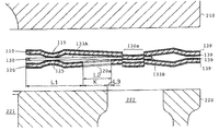
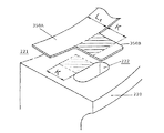
図1は本発明にかかる金属ガスケットの第1形態例を示す分解斜視断面図である。図2は図1に示す金属ガスケットの張出部を避けた位置の部分断面図である。図3は図1に示す金属ガスケットの張出部の位置の部分断面図である。
[First embodiment]
FIG. 1 is an exploded perspective sectional view showing a first embodiment of a metal gasket according to the present invention. FIG. 2 is a partial cross-sectional view of a position where the protruding portion of the metal gasket shown in FIG. 1 is avoided. FIG. 3 is a partial cross-sectional view of the position of the protruding portion of the metal gasket shown in FIG.
金属ガスケット100は、シリンダヘッド側ビード基板110と、シリンダブロック側ビード基板120と、両ビード基板110、120間に配置された副板130とからなり、これらを重ね合わせた状態で、シリンダヘッド210とクローズドデッキシリンダブロック(以下、単にシリンダブロックと記す。)220との接合面間に介装される。
The metal gasket 100 includes a cylinder head
シリンダブロック220には、燃焼室221から遠く離れた所々に、独立した冷却水孔222が設けられている。また、シリンダブロック220の周縁近傍には締付ボルト孔223が所々に設けられている。シリンダヘッド210側にも、シリンダブロック220と同様に冷却水孔212および締付ボルト孔が設けられている。
The
シリンダヘッド側ビード基板110には、シリンダヘッド210の構造に応じて、燃焼室孔111、オイル孔、冷却水孔113およびボルト孔が形成されている。シリンダブロック側ビード基板120には、シリンダブロック220の構造に応じて、燃焼室孔121、オイル孔、冷却水孔123およびボルト孔が形成されている。
In the cylinder head
両ビード基板110、120には、各燃焼室孔111、121を取り囲むようにして環状のビード(ボアービード)115、125が各々形成されている。また、図示されていないが、両ビード基板110、120の各ボルト孔の部分にもビードが各々形成されている。各燃焼室孔111、121を取り囲むようにして形成された環状のビード115、125は、互いの頂部同士が対向状態となるように形成されている。各ボルト孔の部分のビードは、互いの頂部同士が反対向状態となるように形成されている。
The
両ビード基板110、120は、シリンダヘッド210およびシリンダブロック220の接合面の形状・寸法に合わせて形成された、弾性を有する硬質の金属(たとえばステンレス)からなる略長方形の板状部材である、両ビード基板110、120の厚みは、たとえば0.2mmである。
Both
両ビード基板110、120は、各々両面にシール材139が塗布されている。シール材139は、ニトリルまたはフッ素形ゴムからなる。
Both
副板130は、両ビード基板110、120間に挟まれた状態で設けられる軟質または硬質の金属からなる一枚板であり、両ビード基板110、120の燃焼室孔111、121に対応させて形成された燃焼室孔131を有する複数の円環状の部分を連結した形状を有している。副板130の硬度は、両ビード基板110、120の硬度と同等以下に選定されている。
The
副板130は、燃焼室孔131を有する、すなわち燃焼室121を包囲している平板状の副板本体133Aと、副板本体133Aからシリンダヘッド210およびシリンダブロック230の冷却水孔212、222内まで大きく張り出した耳状の張出部133Bとを有し、張出部133Bの先端近傍がかしめ結合により両ビード基板110、120と結合されている。図3に示すように、副板130のかしめ結合部130aは、冷却水孔222内に位置している。
The
シリンダブロック側ビード基板120には、張出部133Bの中間部すなわち、副板本体133Aの外縁からシリンダブロック220の冷却水孔222に至る部分(図1および図3中の範囲Kの部分)に加わる圧力を抑制するべく開口した逃げ孔120aが設けられている。逃げ孔120aは、張出部133Bと十字状に交差するように形成されている。
The cylinder block
図1および図3中のL1は、副板本体133Aの内縁(燃焼室孔131の縁)と外縁との距離を示している。L2は、逃げ孔120aの燃焼室 半径方向における長さを示している。Kは、副板本体133Aの外縁からシリンダブロック220の冷却水孔222までの距離を示している。Sは、逃げ孔120aの張出部133Bと交差する方向の長さを示している。L3は、逃げ孔120aの距離Kに対する余裕長(L2−K)を示している。
L1 in FIG. 1 and FIG. 3 indicates the distance between the inner edge (the edge of the combustion chamber hole 131) and the outer edge of the
図示するように、逃げ孔120aの張出部133Bと交差する方向の長さMおよび燃焼室221半径方向における長さL2は、張出部133Bのそれよりも長く選定されている。また、逃げ孔120aは、冷却水孔212、222内に若干長(余裕長L3に相当)はみ出している。
As shown in the drawing, the length M of the
上記のように構成された金属ガスケット100を、シリンダヘッド210とシリンダブロック220との接合面間に介装し、シリンダヘッド210とシリンダブロック220とをボルト400で締め付けると、両ビード基板110、120に形成された環状のビード115、125を含む全てのビードが圧縮されて変形する。締め付けが完了した時には、副板130の環状のビード115、125の弾性反発力と更にその外側に位置する副板本体133Aの外縁部133cの面圧との相乗作用により、シリンダヘッド210とシリンダブロック220との接合面間がシールされる。
When the metal gasket 100 configured as described above is interposed between the joint surfaces of the
シリンダブロック側ビード基板120に逃げ孔120aが存在することにより、副板130の張出部133Bに加わる締め付け圧力が抑制されるので、締め付けによる最大面圧を副板本体133Aに作用させて、シリンダヘッド210とシリンダブロック220との接合面間を極めて良好に気密にシールすることができる。シリンダヘッド210とシリンダブロック220との接合部に隙間が生じ難いので、面間たたかれの発生を防止して長期間良好なシール性能を維持できる。
The presence of the
[第2形態例]
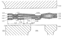
図4は本発明にかかる金属ガスケットの第2形態例を示す部分断面図である。図1〜図3に示した第1形態例と共通の構成要素については同じ符号が付けられている。
[Second embodiment]
FIG. 4 is a partial sectional view showing a second embodiment of the metal gasket according to the present invention. Constituent elements common to the first embodiment shown in FIGS. 1 to 3 are denoted by the same reference numerals.
図4に示す金属ガスケット100は、シリンダヘッド側ビード基板110と副板130との間に第2の副板150が設けられている。第2の副板150は、両ビード基板110、120とほぼ同径同寸に形成されている。第2の副板150を設けることにより、金属ガスケット100の厚さを全体的に増大させることができる。このように第2の副板150を設けた場合も、副板130と接しているビード基板120と第2の副板150のうちの少なくとも一方に逃げ孔120aを設けておくことにより、副板130の張出部133Bに加わる締め付け圧力を抑制することができる。図示の例では、副板130と接しているシリンダブロック側ビード基板120側に逃げ孔120aが設けられている。
In the metal gasket 100 shown in FIG. 4, a second sub plate 150 is provided between the cylinder head
[第3形態例]
図5は本発明にかかる金属ガスケットの第3形態例を示す部分断面図である。図1〜図3に示した第1形態例と共通の構成要素については同じ符号が付けられている。
[Third embodiment]
FIG. 5 is a partial sectional view showing a third embodiment of the metal gasket according to the present invention. Constituent elements common to the first embodiment shown in FIGS. 1 to 3 are denoted by the same reference numerals.
図5に示す金属ガスケット100は、シリンダヘッド側ビード基板110とシリンダブロック側ビード基板120との間に、副板130を収容し得る構造のスペーサ板140を備えている。図5に示す金属ガスケット100の副板130は、図1〜図3に示した副板130よりも厚さの大きいものが使用されている。スペーサ板140の副板収容部は、副板130の面積よりも若干大きめに形成されている。すなわち、副板130の外側面とスペーサ板140の副板収容部の内周壁との間には若干の隙間が形成されている。スペーサ板140の外周部の形状及び寸法は、両ビード基板110、120の外周部のそれに一致させてある。スペーサ板140には、両ビード基板110、120のオイル孔、冷却水孔123およびボルト孔に対応させてオイル孔、冷却水孔およびボルト孔が形成されている。スペーサ板140の厚さは、副板130の厚さよりも薄く選定されている。副板130およびスペーサ板140の厚さを適切に選定することにより、シリンダヘッド210とシリンダブロック220の締結による変形量を適切に制御して両者の接合面間のシール性を向上させることができる。この場合も、シリンダヘッド側ビード基板110とシリンダブロック側ビード基板120のうちの少なくとも一方に逃げ孔120aを設けておくことにより、副板130の張出部133Bに加わる締め付け圧力を抑制することができる。図示の例では、シリンダブロック側ビード基板120側に逃げ孔120aが設けられている。
The metal gasket 100 shown in FIG. 5 includes a
[第4形態例]
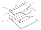
図6は本発明にかかる金属ガスケットの第4形態例を示す部分断面図、図7は同分解斜視図である。図1〜図3に示した第1形態例と共通の構成要素については同じ符号が付けられている。
[Fourth embodiment]
FIG. 6 is a partial sectional view showing a fourth embodiment of the metal gasket according to the present invention, and FIG. 7 is an exploded perspective view thereof. Constituent elements common to the first embodiment shown in FIGS. 1 to 3 are denoted by the same reference numerals.
図6、図7に示す金属ガスケット100は、副板130の各燃焼室孔131の周縁部をそれ以外の部分135よりも厚くするための複数の増厚部材136を備えている。すなわち副板130の各燃焼室孔131の周縁部にこれを縁取る環状の増厚部材136が嵌め付けられ、さらに溶接などの方法で固定されている。増厚部材136の内径寸法は副板130の燃焼室孔131の径と一致するように選定されている。増厚部材136の厚さを適宜選定することにより、両ビード基板110、120の燃焼室孔111、121の周縁部に作用する面圧の調節を行うことができる。したがって、増厚部材136の厚さを適切に選定することにより、両ビード基板110、120間の十分なシール性を確保することができる。この場合も、シリンダヘッド側ビード基板110とシリンダブロック側ビード基板120のうちの少なくとも一方に逃げ孔120aを設けておくことにより、副板130の張出部133Bに加わる締め付け圧力を抑制することができる。図示の例では、シリンダブロック側ビード基板120側に逃げ孔120aが設けられている。
The metal gasket 100 shown in FIGS. 6 and 7 includes a plurality of thickening
この形態例では、副板130の張出部133Bが、逃げ孔120a内に収まるように屈曲させて形成された段差部133Baを有している。このような構造とすることにより、張出部133Bに強い締付け圧が作用するのをより効果的に回避することができる。
In this embodiment, the
図6、図7の例では、環状の増厚部材136を副板130の燃焼室孔131の内壁に嵌め付けて設けることにより増厚部が形成されているが環状の増厚部材136を副板130の各燃焼室孔131の周縁部に重ねて固定することにより増厚部を形成してもよい。また、副板130の燃焼室孔131の内周部を折り返すことにより増厚部を形成してもよいことは無論である。
In the example of FIGS. 6 and 7, the thickened portion is formed by fitting the annular thickening
[第5形態例]
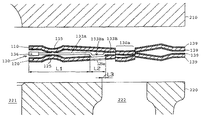
図8は本発明にかかる金属ガスケットの第5形態例を示す分解斜視断面図である。図9は図8に示す金属ガスケットの張出部の位置の部分断面図である。図1〜図3に示した第1形態例と共通の構成要素については同じ符号が付けられている。
[Fifth embodiment]
FIG. 8 is an exploded perspective sectional view showing a fifth embodiment of the metal gasket according to the present invention. 9 is a partial cross-sectional view of the position of the overhanging portion of the metal gasket shown in FIG. Constituent elements common to the first embodiment shown in FIGS. 1 to 3 are denoted by the same reference numerals.
第5形態例に示す金属ガスケット100の副板130は、副板本体133Aから比較的小さく張出した半円状の張出部133Cを有し、張出部133Cがスポット溶接によりシリンダヘッド側ビード基板110と結合されている。図中のXはスポット溶接個所を示している。そして、シリンダブロック側ビード基板120に、張出部133C全体を収容するべく開口した半円状の逃げ孔120bが設けられている。図中のMは、逃げ孔120bおよび張出部133Cの燃焼室221の半径方向における長さをそれぞれ示している。
The sub-plate 130 of the metal gasket 100 shown in the fifth embodiment has a semicircular projecting
このように、副板130の張出部133Cをスポット溶接によりシリンダヘッド側ビード基板110と結合させた場合においても、シリンダブロック側ビード基板120に逃げ孔120bを設けておくことにより、張出部133Bに強い締付け圧が作用するのを効果的に回避することができる。
Thus, even when the overhanging
なお、この例では、張出部133Cをシリンダヘッド側ビード基板110とスポット溶接しているため、シリンダブロック側ビード基板120に逃げ孔120bが設けられているが、張出部133Cをシリンダブロック側ビード基板120とスポット溶接する場合には、シリンダヘッド側ビード基板110側に逃げ孔120bを設けておけばよい。
In this example, since the
また、図8、図9では、各燃焼室孔111、121を取り囲む環状のビード115、125が、互いの頂部同士が反対向状態となるように形成されているが、対向状態となるように形成されていてもかまわない。
Further, in FIGS. 8 and 9, the
100 金属ガスケット
110 シリンダヘッド側ビード基板
111 燃焼室孔
113 冷却水孔
115 環状のビード
120 シリンダブロック側ビード基板
120a 逃げ孔
123 冷却水孔
125 環状のビード
130 副板
130a 結合部
131 燃焼室孔
133A 副板本体
133B 張出部
133Ba 段差部
133C 張出部
136 増厚部材
150 第2の副板
140 スペーサ板
210 シリンダヘッド
212 冷却水孔
220 シリンダブロック
221 燃焼室
222 冷却水孔
223 締付ボルト孔
X スポット溶接個所
DESCRIPTION OF SYMBOLS 100
Claims (1)
燃焼室孔および当該燃焼室孔を取り囲むようにして形成された環状のビードを有し且つ互いの燃焼室孔同士および互いの環状のビード同士を対向させた状態で前記接合面間に設けられる金属性の一対のビード基板と、
前記一対のビード基板間に挟まれた状態で設けられる金属製の副板と、を備え、
前記副板は、前記一対のビード基板の前記燃焼室孔に対応させて形成された燃焼室孔を有する平板状の副板本体と、当該副板本体から外方に張り出した耳状の張出部とを有し、当該張出部の先端部がかしめ結合または溶接により少なくとも一方のビード基板に結合されており、
少なくとも一方のビード基板には、前記張出部に加わる圧力を抑制するべく開口した逃げ孔が設けられていることを特徴とする金属ガスケット。 A metal laminate type gasket provided between the joint surfaces to seal between the joint surfaces of the cylinder head and the cylinder block of the closed deck type engine,
Metal having a combustion chamber hole and an annular bead formed so as to surround the combustion chamber hole, and provided between the joint surfaces in a state where the combustion chamber holes and the annular beads are opposed to each other A pair of bead substrates,
A metal sub-plate provided in a state of being sandwiched between the pair of bead substrates,
The sub-plate includes a flat sub-plate main body having combustion chamber holes formed corresponding to the combustion chamber holes of the pair of bead substrates, and an ear-shaped protrusion protruding outward from the sub-plate main body. And the tip of the overhanging part is joined to at least one bead substrate by caulking or welding,
A metal gasket, wherein at least one of the bead substrates is provided with a relief hole that is open to suppress pressure applied to the overhanging portion.
Priority Applications (1)
| Application Number | Priority Date | Filing Date | Title |
|---|---|---|---|
| JP2004106564A JP2005291079A (en) | 2004-03-31 | 2004-03-31 | Metal gasket |
Applications Claiming Priority (1)
| Application Number | Priority Date | Filing Date | Title |
|---|---|---|---|
| JP2004106564A JP2005291079A (en) | 2004-03-31 | 2004-03-31 | Metal gasket |
Publications (1)
| Publication Number | Publication Date |
|---|---|
| JP2005291079A true JP2005291079A (en) | 2005-10-20 |
Family
ID=35324297
Family Applications (1)
| Application Number | Title | Priority Date | Filing Date |
|---|---|---|---|
| JP2004106564A Pending JP2005291079A (en) | 2004-03-31 | 2004-03-31 | Metal gasket |
Country Status (1)
| Country | Link |
|---|---|
| JP (1) | JP2005291079A (en) |
Cited By (1)
| Publication number | Priority date | Publication date | Assignee | Title |
|---|---|---|---|---|
| KR100793909B1 (en) | 2005-10-21 | 2008-01-15 | 이시카와 가스킷 가부시키가이샤 | Metal Stacked Gaskets |
-
2004
- 2004-03-31 JP JP2004106564A patent/JP2005291079A/en active Pending
Cited By (1)
| Publication number | Priority date | Publication date | Assignee | Title |
|---|---|---|---|---|
| KR100793909B1 (en) | 2005-10-21 | 2008-01-15 | 이시카와 가스킷 가부시키가이샤 | Metal Stacked Gaskets |
Similar Documents
| Publication | Publication Date | Title |
|---|---|---|
| JP2007139177A (en) | Gasket | |
| JP3460819B2 (en) | Head gasket | |
| KR0182062B1 (en) | Metallic gasket with inwardly projecting folded end portion | |
| US8042815B2 (en) | Cylinder head gasket and engine | |
| KR19980032399A (en) | Metal plate gasket | |
| JP2004286213A (en) | Gasket | |
| US8016296B2 (en) | Metal laminate gasket | |
| JP2008202625A (en) | Laminated gasket | |
| JP5077436B2 (en) | Cylinder head gasket | |
| JPH10281289A (en) | Cylinder head gasket | |
| JP4110256B2 (en) | Metal gasket | |
| JP2005291079A (en) | Metal gasket | |
| JP2006125312A (en) | Metal gasket for cylinder head | |
| JP4541399B2 (en) | Metal gasket | |
| JP2008223581A (en) | Metal gasket | |
| JP4360471B2 (en) | Cylinder head gasket | |
| JP2000227047A (en) | Metallic gasket | |
| JP2973118B2 (en) | Metal plate laminated gasket | |
| JP2015129572A (en) | Cylinder head gasket | |
| JP2004239369A (en) | Metallic gasket | |
| JP3119741U (en) | Cylinder head gasket | |
| JP2005201337A (en) | Metal gasket | |
| JP2002323135A (en) | Single-layer metal gasket | |
| JP2010065807A (en) | Cylinder head gasket | |
| JPH1163229A (en) | Laminated metallic gasket |
Legal Events
| Date | Code | Title | Description |
|---|---|---|---|
| A621 | Written request for application examination |
Effective date: 20061219 Free format text: JAPANESE INTERMEDIATE CODE: A621 |
|
| RD03 | Notification of appointment of power of attorney |
Free format text: JAPANESE INTERMEDIATE CODE: A7423 Effective date: 20081114 |
|
| A977 | Report on retrieval |
Free format text: JAPANESE INTERMEDIATE CODE: A971007 Effective date: 20090115 |
|
| A131 | Notification of reasons for refusal |
Free format text: JAPANESE INTERMEDIATE CODE: A131 Effective date: 20090120 |
|
| A02 | Decision of refusal |
Free format text: JAPANESE INTERMEDIATE CODE: A02 Effective date: 20090609 |