JP2005291041A - Engine breather equipment - Google Patents
Engine breather equipment Download PDFInfo
- Publication number
- JP2005291041A JP2005291041A JP2004105110A JP2004105110A JP2005291041A JP 2005291041 A JP2005291041 A JP 2005291041A JP 2004105110 A JP2004105110 A JP 2004105110A JP 2004105110 A JP2004105110 A JP 2004105110A JP 2005291041 A JP2005291041 A JP 2005291041A
- Authority
- JP
- Japan
- Prior art keywords
- breather
- chamber
- balancer shaft
- passage
- generator
- Prior art date
- Legal status (The legal status is an assumption and is not a legal conclusion. Google has not performed a legal analysis and makes no representation as to the accuracy of the status listed.)
- Granted
Links
Images
Landscapes
- Lubrication Details And Ventilation Of Internal Combustion Engines (AREA)
- Lubrication Of Internal Combustion Engines (AREA)
Abstract
【課題】エンジンのブリーザ装置において、ブリーザ通路及びブリーザ室内への油滴の浸入量を低減すると共に、油気分離機能を向上させることを目的としている。
【解決手段】クランクケース1内に、クランク軸3と平行なバランサ軸31を配置しており、バランサ軸31内にバランサ軸芯O2方向に延びるブリーザ通路60を形成する。該ブリーザ通路60の入口61は、クランク室4と隔壁5を隔てたジェネレータ室10に開口し、ブリーザ通路60の出口63はブリーザ室47に開口している。ブリーザ室47は、好ましくは、バランサ軸芯O2と軸芯方向に対向する位置に、ジェネレータカバー15と一体成形し、該ブリーザ室47にバランサ軸31の出口63側の端部を突出させる。また、ブリーザ室47には着脱可能なブリーザ室蓋46を取り付ける。
【選択図】 図3
An object of the present invention is to reduce the amount of oil droplets entering a breather passage and a breather chamber and improve an oil / gas separation function in a breather device of an engine.
A balancer shaft 31 parallel to a crankshaft 3 is disposed in a crankcase 1, and a breather passage 60 extending in the direction of the balancer shaft core O2 is formed in the balancer shaft 31. The inlet 61 of the breather passage 60 opens into the generator chamber 10 separating the crank chamber 4 and the partition wall 5, and the outlet 63 of the breather passage 60 opens into the breather chamber 47. The breather chamber 47 is preferably integrally formed with the generator cover 15 at a position facing the balancer shaft O2 in the axial direction, and the end of the balancer shaft 31 on the outlet 63 side is projected into the breather chamber 47. In addition, a detachable breather chamber lid 46 is attached to the breather chamber 47.
[Selection] Figure 3
Description
本発明は、エンジンのクランクケースのブリーザ装置に関する。 The present invention relates to a breather device for an engine crankcase.
従来、エンジンのブリーザ装置としては、クランクケースのカバー等に複数のフィンを有する迷路状のブリーザ通路を形成した構造(従来技術1)や、クランク軸にブリーザ通路を形成し、該ブリーザ通路と外部とを連通した構造(従来技術2)や、クランク室内に配置したバランサ軸内にブリーザ通路を形成し、該ブリーザ通路と外部とを連通した構造(従来技術3、特許文献1参照)等が提案されている。クランク軸やバランサ軸内にブリーザ通路を形成した構造(従来技術2,3)は、フィン等により迷路状のブリーザ通路を形成した構造(従来技術1)に比べ、コンパクトにできると共に、クランク軸又はバランサ軸の回転による遠心力を利用して、強制的に油気を分離するようにしている。
ところが、前記クランク軸内にブリーザ通路を形成する従来技術2では、クランク軸の端部にジェネレータ又は各種ギヤ類を取り付ける必要性から、クランク軸は軸方向に長くなっており、そのためエンジンの軸方向寸法のコンパクト化が困難である。
However, in the
従来技術3のブリーザ装置は、クランク室内のバランサ軸にブリーザ通路を形成することにより、クランク軸方向のコンパクト性を維持しているが、ブリーザ通路の入口を直接、クランク室に開口しているため、クランク室内で飛散し、充満する油滴がブリーザ通路内に侵入する可能性が大きい。 The breather device of Prior Art 3 maintains the compactness in the direction of the crankshaft by forming the breather passage on the balancer shaft in the crank chamber, but the inlet of the breather passage is directly open to the crank chamber. There is a high possibility that oil droplets scattered and filled in the crank chamber will enter the breather passage.
本発明は上記課題を解決するために創出されたものであり、クランクケース内に、クランク軸とバランサ軸を配置したエンジンにおいて、バランサ軸内にバランサ軸芯方向に延びるブリーザ通路を形成し、該ブリーザ通路の入口は、クランク室と隔壁を隔てたジェネレータ室に開口し、ブリーザ通路の出口は、クランク室外に形成されたブリーザ室を介してエンジン外部に連通している。 The present invention has been created to solve the above-mentioned problems.In an engine in which a crankshaft and a balancer shaft are arranged in a crankcase, a breather passage extending in the balancer axis direction is formed in the balancer shaft. The inlet of the breather passage opens into the generator chamber that separates the crank chamber from the partition wall, and the outlet of the breather passage communicates with the outside of the engine through a breather chamber formed outside the crank chamber.
本発明の前記ブリーザ通路の入口は、好ましくはバランサ軸に設けられたバランサウエイトの径方向外周部に形成され、また、ジェネレータ室の下端部は、スカベンジングポンプのオイル吸込口に連通し、スカベンジングポンプによりジェネレータ室内のオイルを吸い上げる構成とする。 The inlet of the breather passage of the present invention is preferably formed in the radially outer peripheral portion of the balancer weight provided on the balancer shaft, and the lower end portion of the generator chamber communicates with the oil suction port of the scavenging pump, The pump is configured to suck up the oil in the generator chamber by the pump.
また、本発明は、前記ジェネレータ室を覆うジェネレータカバーの外側面にブリーザ室を一体に形成し、バランサ軸の軸方向一端部を上記ブリーザ室内に突出させ、該ブリーザ室内に前記ブリーザ通路の出口を開口し、ブリーザ室にはブリーザ室蓋を着脱可能に取り付ける。 Further, according to the present invention, a breather chamber is integrally formed on the outer surface of the generator cover that covers the generator chamber, and one end portion in the axial direction of the balancer shaft is projected into the breather chamber, and an outlet of the breather passage is formed in the breather chamber The breather chamber lid is detachably attached to the breather chamber.
また、本発明は、バランサ軸の一端をブリーザ室に突出させる構造において、バランサ軸のブリーザ室内部分にタイミング調節用工具係合部を形成し、ブリーザ室蓋を取り外した状態で、エンジン外部から上記工具係合部に回転用工具を係合可能とする。 Further, the present invention provides a structure in which one end of the balancer shaft projects into the breather chamber, a timing adjusting tool engaging portion is formed in the breather chamber portion of the balancer shaft, and the breather chamber lid is removed from the outside of the engine. A tool for rotation can be engaged with the tool engaging portion.
(1)バランサ軸内にブリーザ通路を形成していることにより、バランサ軸の回転遠心力により、ブリーザ通路内に浸入しようとする油滴の一部(たとえば大きな油滴)を排除できる。また、ブリーザ通路内に侵入した細かい油滴に対しても、バランサ軸の回転遠心力により、強制的に油気分離することができる。すなわち、バランサ軸の回転を利用することにより、油気分離機能が向上する。 (1) Since the breather passage is formed in the balancer shaft, a part of the oil droplets (for example, large oil droplets) to enter the breather passage can be eliminated by the rotational centrifugal force of the balancer shaft. In addition, fine oil droplets that have entered the breather passage can be forcibly separated by the rotational centrifugal force of the balancer shaft. That is, the oil / air separation function is improved by utilizing the rotation of the balancer shaft.
(2)バランサ軸にバランサ軸芯方向のブリーザ通路を形成しているため、従来のようにクランク軸内にブリーザ通路を形成する場合に比べ、バランサ軸の軸方向端部にブリーザ室を形成したとしても、エンジンのクランク軸方向寸法のコンパクト化を維持することができる。 (2) Since the breather passage in the balancer shaft direction is formed on the balancer shaft, a breather chamber is formed at the axial end of the balancer shaft as compared with the conventional case where the breather passage is formed in the crankshaft. Even so, the size of the engine in the crankshaft direction can be kept compact.
(3)ジェネレータ室は、クランク室に比べると容積が大きく、しかも、油滴の量が少ない部屋であり、このジェネレータ室に、ブリーザ通路の入口を開口させているので、従来のようにクランク室にブリーザ入口を開口する構造と比較して、ブリーザ通路内に侵入する可能性のある油滴を少なくすることができる。 (3) The generator chamber is larger in volume than the crank chamber and has a small amount of oil droplets. Since the inlet of the breather passage is opened in this generator chamber, Compared with the structure in which the breather inlet is opened, oil droplets that can enter the breather passage can be reduced.
(4)ブリーザ通路の入口を、バランサ軸に設けられたバランサウエイトの径方向外周部に形成すると、バランサ軸の回転による遠心力作用が増大され、ブリーザ通路の入口における油気分離機能が向上する。 (4) If the inlet of the breather passage is formed in the radially outer peripheral portion of the balancer weight provided in the balancer shaft, the centrifugal force action due to the rotation of the balancer shaft is increased, and the oil / air separation function at the inlet of the breather passage is improved. .
(5)ジェネレータ室をスカベンジングポンプのオイル吸込口に連通し、スカベンジングポンプによりジェネレータ室内のオイルを吸い上げる構成とすることにより、ブリーザ通路の入口から浸入しようとする油滴量を一層減少させることができる。 (5) By connecting the generator chamber to the oil suction port of the scavenging pump and sucking up the oil in the generator chamber by the scavenging pump, the amount of oil droplets entering the breather passage can be further reduced. Can do.
(6)ジェネレータカバーの外側面にブリーザ室を一体に形成し、バランサ軸を上記ブリーザ室内に突出させ、該ブリーザ室内に前記ブリーザ通路の出口を開口し、前記ブリーザ室にブリーザ室蓋を着脱可能に取り付けてあると、ブリーザ通路からブリーザ室への通路形成が簡単になり、また、ジェネレータカバーを外さなくとも、小さなブリーザ室蓋を取り外すだけで、ブリーザ通路のメンテナンス及び掃除が簡単に行える。 (6) A breather chamber is integrally formed on the outer surface of the generator cover, a balancer shaft is projected into the breather chamber, an outlet of the breather passage is opened in the breather chamber, and a breather chamber lid can be attached to and detached from the breather chamber. If it is attached, the passage formation from the breather passage to the breather chamber becomes easy, and maintenance and cleaning of the breather passage can be easily performed by removing the small breather chamber lid without removing the generator cover.
(7)バランサ軸のブリーザ室内部分にタイミング調節用工具係合部を形成してあると、ブリーザ室蓋のみを取り外すだけで、エンジン外部から上記工具係合部に回転用工具を係合でき、それにより、バランサ軸を介してクランク軸を手動で回転させ、吸、排気弁の開開タイミングの調節を行うことができる。 (7) If the timing adjusting tool engaging portion is formed in the breather chamber portion of the balancer shaft, the rotating tool can be engaged with the tool engaging portion from the outside of the engine only by removing the lid of the breather chamber. Thereby, the crankshaft can be manually rotated via the balancer shaft, and the opening / closing timing of the intake and exhaust valves can be adjusted.
[クランクケース内構造の概略]
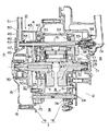
図1〜図5は、本発明をセミドライサンプ型の単気筒4サイクルエンジンに適用した実施の形態である。図2は、クランク軸芯O1、バランサ軸芯O2及びポンプ軸芯O3を通る切断面の展開図(図1のII-II断面展開図)であり、クランクケース1は左右のクランクケース部材1a、1bを結合することにより構成されており、クランク軸3を収納するクランク室4は、左右のクランクケース部材1a,1bの隔壁5,6とクランク室周壁7とで囲まれている。クランク室周壁7はクランク室4の下側から後方を円弧状に覆っている。クランク室4の左側には左側隔壁5を隔ててジェネレータ室10が形成され、クランク室4の右側には右側隔壁6を隔てて伝動ギヤ室11及びクラッチ室12が形成されている。ジェネレータ室10は左方からジェネレータカバー15により覆われており、該ジェネレータカバー15はボルト16により、左側クランクケース部材1aの左端面(ジェネレータカバー取付面)に着脱可能に取り付けられている。
[Outline of crankcase structure]
1 to 5 show an embodiment in which the present invention is applied to a semi-dry sump type single-cylinder four-cycle engine. FIG. 2 is a developed view of a cut surface passing through the crankshaft core O1, the balancer shaft core O2, and the pump shaft core O3 (II-II cross-sectional developed view of FIG. 1). The
クランク軸3は左右の隔壁5,6に嵌着された軸受17,18により回転可能に両持ち状に支持されている。クランク軸3の右端部は、右側の軸受18から伝動ギヤ室11内に突出すると共に、クランクギヤ20及びポンプ駆動ギヤ21が固着されている。クランク軸3の左端部は左側の軸受17からジェネレータ室10内に突出すると共に、バランサ駆動ギヤ25及びカム駆動チェーン用ギヤ(スプロケットギヤ)26が設けられており、さらに、左先端部にはジェネレータ30のロータ部30aが固定されている。
The
クランク軸3より前方位置のクランク室4内部分には、クランク軸3と平行なバランサ軸31が配置されており、該バランサ軸31は前記左右の隔壁5,6に軸受33,34を介して両持ち状に回転可能に支持されている。バランサ軸31の右端部は、前記伝動ギヤ室11に突出すると共に、右サイドウエイト36が一体成形されている。また、バランサ軸31の軸方向の右端面には、ウォーターポンプ38のポンプ軸39が同一軸芯O2上で連結しており、バランサ軸31によりウォーターポンプ38を駆動するようになっている。
A
バランサ軸31の左端部はジェネレータ室10内に突出しており、該左端突出部分には、バランサギヤ40及び左サイドウエイト41が右側から順にスプライン嵌合し、これらバランサギヤ40及び左側サイドウエイト41は、バランサ軸31に螺着された締付ナット43により軸方向移動不能に固定されている。
The
クランク室4の後側には、クランク室周壁7を隔ててミッション室8が形成されており、該ミッション室8内には、トランスミッションが収納されると共に、エンジン潤滑冷却用のオイル(潤滑油)が一定高さまで貯留されている。トランスミッション室8の左右の隔壁部分には、同一軸芯O3上にスカベンジングポンプ75とフィードポンプ74とが左右に分配設置されており、右側のフィードポンプ74は、トランスミッション室8内のオイルをクランク軸3やカム軸の各潤滑箇所に供給し、左側のスカベンジングポンプ75は、ジェネレータ室10やクランク室4に戻ってきた使用後のオイルを、クランク室4の前部下側に形成されたスカベンジング室76(図1)を介して汲み上げ、トランスミッション室8に戻すようになっている。
A
[ブリーザ装置]
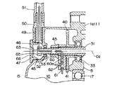
図3は図2の矢印III部分であり、ブリーザ装置の拡大断面図である。この図3において、ジェネレータカバー15の外側面(左側面)には、前記バランサ軸芯O2と同一軸芯上に左端開口状の円筒型ブリーザケース45が一体に形成されており、該ブリーザケース45の左端開口にはブリーザ室蓋46が着脱自在に螺着され、ブリーザケース45とブリーザ室蓋46によりブリーザ室47を形成している。該ブリーザ室47の前上端部には空気出口通路49が形成され、該空気出口通路49にはボルト継手管50が螺着され、該ボルト継手管50には空気排出用ゴムホース51が接続している。該ゴムホース51は外部に開放しているが、エアクリーナに接続することも可能である。ブリーザ室蓋46の左側面には、コイン係合用のスリット66が形成され、該スリット66にコインを係合し、ブリーザ室蓋46を回転することにより、ブリーザ室蓋46を着脱するようになっている。
[Breaser device]
FIG. 3 is an enlarged cross-sectional view of the breather device, taken along arrow III in FIG. In FIG. 3, a
バランサ軸31の左端部は、ジェネレータ室10内からブリーザケース45の右端貫通孔52を通ってブリーザ室47内に突出しており、貫通孔52の内周面にはシール部材53が嵌着され、該シール部材53によりバランサ軸31の外周面を回転可能にシールしている。
The left end portion of the
バランサ軸31の軸芯部分には、バランサ軸芯O2方向に延びるブリーザ通路60が形成されており、該ブリーザ通路60の左端は、ブリーザ通路60の出口63として、バランサ軸31の左側軸端面からブリーザ室47に直接開口している。ジェネレータ室10内に位置する左サイドウエイト41内には、ブリーザ通路60に連通すると共に径方向外方に延びるブリーザ入口通路60aが形成されており、該ブリーザ入口通路60aの径方向外周端は、ブリーザ通路60の入口61として、左側サイドウエイト41の径方向外周端面からジェネレータ室10に開口している。さらに、ブリーザ入口通路60aの外周端寄りの部分には、ジェネレータ室10に対して軸芯方向に開口する副入口62が形成されている。バランサ軸31のブリーザ室47内部分の外周面には、多角形状、たとえば六角形状の回転用の工具係合部65が形成されており、該回転用工具係合部65の最大外径は、ブリーザケース45の貫通孔52の内径よりも小さく形成され、これにより、ジェネレータカバー15をクランクケース部材1aに装着する際、貫通孔53を工具係合部65が通過できるようになっている。ブリーザ通路60の右端部は、図2に示すようにバランサ軸31の右端部近傍まで延びているが、閉塞されており、右方に空気が抜けないようになっている。
A
[ジェネレータ室内の構成]
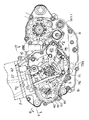
図1はジェネレータカバーを外して示すクランクケースの左側面図であり、クランク軸3のカム駆動チェーン用ギヤ26に巻き掛けられたカム駆動チェーン27は、左側クランクケース部材1aの前上端部に形成されたチェーン通路67及びシリンダ2の左端部に形成されたチェーン通路を通ってシリンダヘッド(図示せず)の上側まで上方に延び、吸、排気弁用の各カム軸の駆動スプロケットに巻き掛けられており、クランク軸3の回転(R1方向)によって矢印S方向に移動し、カム軸を回転駆動するようになっている。バランサ軸31は、クランク軸3と概ね同じ高さに配置されると共に前述のようにクランク軸3よりも前方位置に配置されているが、バランサ駆動ギヤ25及び該ギヤ25と同一径のバランサギヤ40の径を大きく取ることにより、左サイドウエイト41が、左側方から見てカム駆動チェーン27と重ならない位置まで前方に寄せられている。また、左サイドウエイト41に形成された前記ブリーザ入口通路60aは、たとえば放射状に2本形成され、各ブリーザ入口通路60aにそれぞれ入口61及び副入口62が形成されている。
[Configuration of generator room]
FIG. 1 is a left side view of the crankcase with the generator cover removed, and a
ジェネレータ室10の下端部は、オイル流通孔71を介してクランク室4の前部下側の前記スカベンジング室76に連通し、該スカベンジング室76にはスカベンジングポンプ75の下端吸込口75aが開口している。エンジン運転中、スカベンジングポンプ75の吸引作用により、ジェネレータ室10内及びスカベンジング室74内のオイルは殆ど吸引され、クランク室後方のミッション室8に戻されるようになっている。すなわち、運転中、ジェネレータ室10はオイルが殆ど吸い出された状態に保たれている。
A lower end portion of the
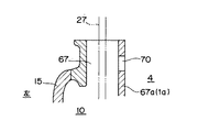
図5は図1のV-V断面拡大部分図であり、左側クランクケース部材1aのチェーン通路67の右端壁67aには、チェーン通路67内とクランク室4内とを空気流通可能に連通する2個の連通孔70が形成されており、該連通孔70及び前記左側軸受17を介してクランク室4のブローバイガスがジェネレータ室10に流入すると共に、クランク室4内の圧力変化がジェネレータ室10内に伝わり、ジェネレータ室10内もクランク室4内と同様な圧力変化を生じるようになっている。
FIG. 5 is an enlarged partial view of the VV cross section of FIG. 1, and two
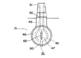
図4はブリーザ室47の左側面拡大図であり、ブリーザ室47の下端にはオイル排出通路80が形成され、該オイル排出通路80はパイプ又はチューブ等によりスカベンジング室76に連通している。なお、上記のようにオイル排出通路80をスカベンジング室76に連通する代わりに、ジェネレータ室10に連通することも可能であるが、上記のようにスカベンジング室76に連通していることにより、スカベンジングポンプ75の吸引力を利用して、積極的にブリーザ室47に溜まるオイルを排出することができる。
FIG. 4 is an enlarged left side view of the
[作用]
図2において、エンジン運転中、クランク室4内は、ピストンとシリンダの間から漏れるブローバイガスが充満し、また、クランク室4内の底部から掻き揚げられるオイルが油滴(オイルミスト)となってブローバイガス中に浮遊しており、前記ブローバイガスは図5の連通孔70及び左側軸受17を介してジェネレータ室10に流入している。また、クランク室4内の圧力は、ピストンの昇降により周期的に変化しており、この圧力変化も連通孔70及び左側軸受17を介してジェネレータ室10にも伝達されている。
[Action]
In FIG. 2, during engine operation, the
図3において、ジェネレータ室10内のガスは、ジェネレータ室10の圧力変化により、左サイドウエイト41の入口61及び副入口62からブリーザ入口通路60aに入り、バランサ軸31内のブリーザ通路60を経てブリーザ室47に流入するが、入口61,62、ブリーザ入口通路60a、ブリーザ通路60及びブリーザ室47において油気分離される。ブリーザ室47内で油気分離された後の気体成分はゴムホース51を通って外部又はエアクリーナに排出され、分離後の油成分はオイル排出通路80(図4)を経てスカベンジング室76に戻される。
In FIG. 3, the gas in the
前記のようなブローバイガスの排出工程における油気分離作用を、さらに詳しく説明する。図3において、ジェネレータ室10はクランク室4と比べると容積が大きく、ガス中に含まれる油滴成分が少なく、しかも、スカベンジングポンプ75(図1)により常時オイルが吸い出されており、これらにより、左サイドウエイト41の入口61,62からブリーザ通路60内に浸入しようとする油滴成分は、従来のようにクランク室内に入口を開口する場合に比べて、格段と少ない量に減少している。これに加え、バランサ軸31はクランク軸3と同一回転速度で回転しているので、左サイドウエイト41の外周端部近傍では、大きな油滴は遠心力により分離され、入口61,62から浸入することは殆どない。
The oil / gas separation action in the blow-by gas discharge process will be described in more detail. In FIG. 3, the
また、ジェネレータ室10には、カム軸部分からチェーン通路67を通ってオイルが戻ってくるが、入口61,52を有する左サイドウエイト41は、図1のようにカム駆動チェーン27から前方に離れて位置しているので、カム駆動チェーン27と共にジェネレータ室10に戻ってくるオイルが前記入口61,62から浸入する可能性も極めて小さい。
Further, the oil returns to the
前記入口通路60aを通ってブリーザ通路60内に流入した油滴も、バランサ軸31の回転による遠心力によってブリーザ通路60の内周面に付着することにより、気体成分から分離され、さらに、ブリーザ室47に流入することにより、ブリーザ室47内でも分離される。
Oil droplets that flow into the
また、本実施の形態では、入口通路60aは2本形成され、さらに各入口通路60aには径方向に開口する入口61と軸芯方向に開口する副入口62が形成されているので、一方の入口通路60aが詰まった場合には、残りの入口通路60aのみでブリーザ機能を維持でき、また、1つの入口通路60aの入口61又は副入口62の一方が詰まった場合には、残りの入口でブリーザ機能を維持できる。
In the present embodiment, two
[ブリーザ通路のメンテナンス及びタイミング調節]
吸、排気弁の開閉タイミングの調節をする場合には、図3のブリーザ室蓋46をジェネレータカバー15から取り外し、左端開口からボックスレンチ等の回転用工具をブリーザ室47内に挿入し、バランサ軸31の工具係合部65に係合する。そして、回転用工具によってバランサ軸31を手動で回転することにより、クランク軸3を回転させ、上記開閉タイミングの調節を行う。このように、ジェネレータカバー15を取り外すことなく、開閉タイミングの調節作業後を行うことができる。
[Maintenance and timing adjustment of breather passage]
When adjusting the opening and closing timings of the intake and exhaust valves, the
[その他の発明の実施の形態]
(1)前記実施の形態では、オイルをクランクケース内のミッション室に貯留するセミドライサンプ型の単気筒4サイクルエンジンに適用したが、オイルタンクをエンジン外部に設置した外部オイルタンク設置型のエンジンに適用することも可能であり、また、単気筒4サイクルエンジン以外でも、クランクケース内にバランサ軸を備えるエンジンであれば本発明の適用は可能である。
[Other Embodiments of the Invention]
(1) In the above-described embodiment, the present invention is applied to a semi-dry sump type single-cylinder four-cycle engine that stores oil in a transmission chamber in a crankcase. The present invention can be applied to any engine other than the single-cylinder four-cycle engine provided that it has a balancer shaft in the crankcase.
(2)前記実施の形態では、ブリーザ通路の入口をサイドウエイトに形成しているが、バランサ軸の外周面に、ジェネレータに向けて開口する構造とすることもできる。また、ジェネレータ室に開口する入口は、前記実施の形態のような4つに限定されるものではなく、1個、2個3個又は5個以上形成することも可能である。 (2) In the above-described embodiment, the inlet of the breather passage is formed in the side weight. However, a structure may be adopted in which the outer peripheral surface of the balancer shaft opens toward the generator. Further, the number of inlets that open to the generator chamber is not limited to four as in the above-described embodiment, and may be one, two, three, or five or more.
1 クランクケース
3 クランク軸
4 クランク室
8 トランスミッション室
10 ジェネレータ室
15 ジェネレータカバー
30 ジェネレータ
31 バランサ軸
41 左サイドウエイト
45 ブリーザケース
46 ブリーザ室蓋
47 ブリーザ室
60 ブリーザ通路
60a ブリーザ入口通路
61、62 ブリーザ通路の入口
63 ブリーザ通路の出口
76 スカベンジング室
75 スカベンジングポンプ
1
Claims (5)
バランサ軸内にバランサ軸芯方向に延びるブリーザ通路を形成し、該ブリーザ通路の入口は、クランク室と隔壁を隔てたジェネレータ室に開口し、ブリーザ通路の出口は、クランク室外に形成されたブリーザ室を介してエンジン外部に連通していることを特徴とするエンジンのブリーザ装置。 In an engine that has a crankshaft and a balancer shaft in the crankcase,
A breather passage extending in the balancer shaft direction is formed in the balancer shaft, an inlet of the breather passage is opened to a generator chamber separated from the crank chamber and a partition wall, and an outlet of the breather passage is formed outside the crank chamber A breather device for an engine, wherein the breather device communicates with the outside of the engine via
ブリーザ室にはブリーザ室蓋を着脱可能に取り付けてあることを特徴とする請求項1〜3のいずれかに記載のエンジンのブリーザ装置。 A breather chamber is integrally formed on the outer surface of the generator cover that covers the generator chamber, one end of the balancer shaft in the axial direction is projected into the breather chamber, and an outlet of the breather passage is opened in the breather chamber.
The breather device for an engine according to any one of claims 1 to 3, wherein a breather chamber lid is detachably attached to the breather chamber.
ブリーザ室蓋を取り外した状態で、エンジン外部から上記工具係合部に回転用工具を係合可能としていることを特徴とする請求項4記載のエンジンのブリーザ装置。
A tool engaging part for timing adjustment is formed in the breather chamber portion of the balancer shaft,
5. The breather device for an engine according to claim 4, wherein the tool for rotation can be engaged with the tool engaging portion from the outside of the engine with the breather chamber lid removed.
Priority Applications (1)
| Application Number | Priority Date | Filing Date | Title |
|---|---|---|---|
| JP2004105110A JP4439972B2 (en) | 2004-03-31 | 2004-03-31 | Engine breather equipment |
Applications Claiming Priority (1)
| Application Number | Priority Date | Filing Date | Title |
|---|---|---|---|
| JP2004105110A JP4439972B2 (en) | 2004-03-31 | 2004-03-31 | Engine breather equipment |
Publications (2)
| Publication Number | Publication Date |
|---|---|
| JP2005291041A true JP2005291041A (en) | 2005-10-20 |
| JP4439972B2 JP4439972B2 (en) | 2010-03-24 |
Family
ID=35324265
Family Applications (1)
| Application Number | Title | Priority Date | Filing Date |
|---|---|---|---|
| JP2004105110A Expired - Fee Related JP4439972B2 (en) | 2004-03-31 | 2004-03-31 | Engine breather equipment |
Country Status (1)
| Country | Link |
|---|---|
| JP (1) | JP4439972B2 (en) |
Cited By (8)
| Publication number | Priority date | Publication date | Assignee | Title |
|---|---|---|---|---|
| JP2007146772A (en) * | 2005-11-29 | 2007-06-14 | Honda Motor Co Ltd | Blow-by gas ventilation system for internal combustion engines |
| JP2009013813A (en) * | 2007-07-02 | 2009-01-22 | Toyota Motor Corp | Lubricating device for internal combustion engine |
| CN101368498B (en) * | 2007-08-15 | 2011-02-09 | 通用汽车环球科技运作公司 | Forced crankcase ventilation system for an internal combustion engine |
| JP2011032977A (en) * | 2009-08-04 | 2011-02-17 | Suzuki Motor Corp | Cam chain lubrication structure of motorcycle engine |
| JP2017106342A (en) * | 2015-12-08 | 2017-06-15 | スズキ株式会社 | Water-cooled engine |
| CN109681291A (en) * | 2019-02-01 | 2019-04-26 | 宁波市龙嘉摩托车有限公司 | A kind of centrifugal gas oil separation structure of balance shaft |
| JP2019124137A (en) * | 2018-01-12 | 2019-07-25 | トヨタ自動車株式会社 | Internal combustion engine |
| WO2025126543A1 (en) * | 2023-12-12 | 2025-06-19 | カワサキモータース株式会社 | Engine |
-
2004
- 2004-03-31 JP JP2004105110A patent/JP4439972B2/en not_active Expired - Fee Related
Cited By (9)
| Publication number | Priority date | Publication date | Assignee | Title |
|---|---|---|---|---|
| JP2007146772A (en) * | 2005-11-29 | 2007-06-14 | Honda Motor Co Ltd | Blow-by gas ventilation system for internal combustion engines |
| JP2009013813A (en) * | 2007-07-02 | 2009-01-22 | Toyota Motor Corp | Lubricating device for internal combustion engine |
| CN101368498B (en) * | 2007-08-15 | 2011-02-09 | 通用汽车环球科技运作公司 | Forced crankcase ventilation system for an internal combustion engine |
| US8166958B2 (en) | 2007-08-15 | 2012-05-01 | GM Global Technology Operations LLC | Positive crankcase ventilation system for an internal combustion engine |
| JP2011032977A (en) * | 2009-08-04 | 2011-02-17 | Suzuki Motor Corp | Cam chain lubrication structure of motorcycle engine |
| JP2017106342A (en) * | 2015-12-08 | 2017-06-15 | スズキ株式会社 | Water-cooled engine |
| JP2019124137A (en) * | 2018-01-12 | 2019-07-25 | トヨタ自動車株式会社 | Internal combustion engine |
| CN109681291A (en) * | 2019-02-01 | 2019-04-26 | 宁波市龙嘉摩托车有限公司 | A kind of centrifugal gas oil separation structure of balance shaft |
| WO2025126543A1 (en) * | 2023-12-12 | 2025-06-19 | カワサキモータース株式会社 | Engine |
Also Published As
| Publication number | Publication date |
|---|---|
| JP4439972B2 (en) | 2010-03-24 |
Similar Documents
| Publication | Publication Date | Title |
|---|---|---|
| JP4698623B2 (en) | Breather device for internal combustion engine | |
| JP5484142B2 (en) | Engine breather equipment | |
| JP4960901B2 (en) | Engine breather equipment | |
| JP2017219014A (en) | Gas-liquid separation device for blow-by gas of engine | |
| JP4439972B2 (en) | Engine breather equipment | |
| JP4919168B2 (en) | Engine lubrication equipment | |
| JP2004108257A (en) | Internal combustion engine lubrication system | |
| JPH11303617A (en) | Engine for outboard motor | |
| JP2009068405A (en) | Engine lubrication equipment | |
| JP5261814B2 (en) | Internal combustion engine | |
| JP4573762B2 (en) | Lubricating device for internal combustion engine | |
| JP3980313B2 (en) | Engine lubrication structure | |
| JP2014070535A (en) | Crankcase emission control system | |
| JPH0559925A (en) | Lubricating device of internal combustion engine | |
| JP4467916B2 (en) | Breather device for internal combustion engine | |
| JP4372481B2 (en) | Motorcycle engine and motorcycle equipped with the engine | |
| JP4124301B2 (en) | Vehicle engine | |
| JP4275479B2 (en) | Motorcycle engine and motorcycle equipped with the engine | |
| JP5919864B2 (en) | engine | |
| JP6102468B2 (en) | Engine breather structure | |
| JP2009180193A (en) | Internal combustion engine | |
| JP4495418B2 (en) | Motorcycle engine and motorcycle equipped with the engine | |
| JP2009052421A (en) | Engine lubrication equipment | |
| JP3870737B2 (en) | Oil return structure for outboard motor | |
| JP6061752B2 (en) | Internal combustion engine |
Legal Events
| Date | Code | Title | Description |
|---|---|---|---|
| A621 | Written request for application examination |
Free format text: JAPANESE INTERMEDIATE CODE: A621 Effective date: 20060915 |
|
| RD03 | Notification of appointment of power of attorney |
Free format text: JAPANESE INTERMEDIATE CODE: A7423 Effective date: 20080131 |
|
| A977 | Report on retrieval |
Free format text: JAPANESE INTERMEDIATE CODE: A971007 Effective date: 20090514 |
|
| A131 | Notification of reasons for refusal |
Free format text: JAPANESE INTERMEDIATE CODE: A131 Effective date: 20090707 |
|
| A521 | Written amendment |
Free format text: JAPANESE INTERMEDIATE CODE: A523 Effective date: 20090903 |
|
| TRDD | Decision of grant or rejection written | ||
| A01 | Written decision to grant a patent or to grant a registration (utility model) |
Free format text: JAPANESE INTERMEDIATE CODE: A01 Effective date: 20091222 |
|
| A01 | Written decision to grant a patent or to grant a registration (utility model) |
Free format text: JAPANESE INTERMEDIATE CODE: A01 |
|
| A61 | First payment of annual fees (during grant procedure) |
Free format text: JAPANESE INTERMEDIATE CODE: A61 Effective date: 20100106 |
|
| FPAY | Renewal fee payment (event date is renewal date of database) |
Free format text: PAYMENT UNTIL: 20130115 Year of fee payment: 3 |
|
| R150 | Certificate of patent or registration of utility model |
Ref document number: 4439972 Country of ref document: JP Free format text: JAPANESE INTERMEDIATE CODE: R150 Free format text: JAPANESE INTERMEDIATE CODE: R150 |
|
| FPAY | Renewal fee payment (event date is renewal date of database) |
Free format text: PAYMENT UNTIL: 20130115 Year of fee payment: 3 |
|
| FPAY | Renewal fee payment (event date is renewal date of database) |
Free format text: PAYMENT UNTIL: 20140115 Year of fee payment: 4 |
|
| FPAY | Renewal fee payment (event date is renewal date of database) |
Free format text: PAYMENT UNTIL: 20150115 Year of fee payment: 5 |
|
| LAPS | Cancellation because of no payment of annual fees |