JP2005291002A - Diesel engine - Google Patents
Diesel engine Download PDFInfo
- Publication number
- JP2005291002A JP2005291002A JP2004103050A JP2004103050A JP2005291002A JP 2005291002 A JP2005291002 A JP 2005291002A JP 2004103050 A JP2004103050 A JP 2004103050A JP 2004103050 A JP2004103050 A JP 2004103050A JP 2005291002 A JP2005291002 A JP 2005291002A
- Authority
- JP
- Japan
- Prior art keywords
- egr
- combustion
- egr device
- egr rate
- external
- Prior art date
- Legal status (The legal status is an assumption and is not a legal conclusion. Google has not performed a legal analysis and makes no representation as to the accuracy of the status listed.)
- Granted
Links
Images

Classifications
-
- F—MECHANICAL ENGINEERING; LIGHTING; HEATING; WEAPONS; BLASTING
- F02—COMBUSTION ENGINES; HOT-GAS OR COMBUSTION-PRODUCT ENGINE PLANTS
- F02D—CONTROLLING COMBUSTION ENGINES
- F02D41/00—Electrical control of supply of combustible mixture or its constituents
- F02D41/30—Controlling fuel injection
- F02D41/3011—Controlling fuel injection according to or using specific or several modes of combustion
- F02D41/3017—Controlling fuel injection according to or using specific or several modes of combustion characterised by the mode(s) being used
- F02D41/3035—Controlling fuel injection according to or using specific or several modes of combustion characterised by the mode(s) being used a mode being the premixed charge compression-ignition mode
-
- F—MECHANICAL ENGINEERING; LIGHTING; HEATING; WEAPONS; BLASTING
- F02—COMBUSTION ENGINES; HOT-GAS OR COMBUSTION-PRODUCT ENGINE PLANTS
- F02D—CONTROLLING COMBUSTION ENGINES
- F02D41/00—Electrical control of supply of combustible mixture or its constituents
- F02D41/0025—Controlling engines characterised by use of non-liquid fuels, pluralities of fuels, or non-fuel substances added to the combustible mixtures
- F02D41/0047—Controlling exhaust gas recirculation [EGR]
- F02D41/006—Controlling exhaust gas recirculation [EGR] using internal EGR
-
- F—MECHANICAL ENGINEERING; LIGHTING; HEATING; WEAPONS; BLASTING
- F02—COMBUSTION ENGINES; HOT-GAS OR COMBUSTION-PRODUCT ENGINE PLANTS
- F02D—CONTROLLING COMBUSTION ENGINES
- F02D41/00—Electrical control of supply of combustible mixture or its constituents
- F02D41/0025—Controlling engines characterised by use of non-liquid fuels, pluralities of fuels, or non-fuel substances added to the combustible mixtures
- F02D41/0047—Controlling exhaust gas recirculation [EGR]
- F02D41/0065—Specific aspects of external EGR control
-
- F—MECHANICAL ENGINEERING; LIGHTING; HEATING; WEAPONS; BLASTING
- F02—COMBUSTION ENGINES; HOT-GAS OR COMBUSTION-PRODUCT ENGINE PLANTS
- F02D—CONTROLLING COMBUSTION ENGINES
- F02D41/00—Electrical control of supply of combustible mixture or its constituents
- F02D41/0025—Controlling engines characterised by use of non-liquid fuels, pluralities of fuels, or non-fuel substances added to the combustible mixtures
- F02D41/0047—Controlling exhaust gas recirculation [EGR]
- F02D41/005—Controlling exhaust gas recirculation [EGR] according to engine operating conditions
- F02D41/0057—Specific combustion modes
-
- Y—GENERAL TAGGING OF NEW TECHNOLOGICAL DEVELOPMENTS; GENERAL TAGGING OF CROSS-SECTIONAL TECHNOLOGIES SPANNING OVER SEVERAL SECTIONS OF THE IPC; TECHNICAL SUBJECTS COVERED BY FORMER USPC CROSS-REFERENCE ART COLLECTIONS [XRACs] AND DIGESTS
- Y02—TECHNOLOGIES OR APPLICATIONS FOR MITIGATION OR ADAPTATION AGAINST CLIMATE CHANGE
- Y02T—CLIMATE CHANGE MITIGATION TECHNOLOGIES RELATED TO TRANSPORTATION
- Y02T10/00—Road transport of goods or passengers
- Y02T10/10—Internal combustion engine [ICE] based vehicles
- Y02T10/40—Engine management systems
Landscapes
- Engineering & Computer Science (AREA)
- Chemical & Material Sciences (AREA)
- Combustion & Propulsion (AREA)
- Mechanical Engineering (AREA)
- General Engineering & Computer Science (AREA)
- Output Control And Ontrol Of Special Type Engine (AREA)
- Exhaust-Gas Circulating Devices (AREA)
- Electrical Control Of Air Or Fuel Supplied To Internal-Combustion Engine (AREA)
- Combined Controls Of Internal Combustion Engines (AREA)
Abstract
【課題】 予混合燃焼と通常燃焼との切り換えに際してEGR率を迅速に制御できるディーゼルエンジンを提供する。
【解決手段】 燃料噴射装置9と、外部EGR装置19と、内部EGR装置29と、燃料噴射装置9、外部EGR装置19及び内部EGR装置29を制御する制御装置26とを備え、制御装置26は、所定の運転領域では、燃料を上死点近傍よりも早期に噴射すると共に比較的多量のEGRを実行して予混合燃焼を実行させ、所定の運転領域外では、燃料を上死点近傍で噴射すると共に少量のEGRを実行して通常燃焼を実行させるものであり、制御装置26は、予混合燃焼を実行させるときは、外部EGR装置19及び内部EGR装置29の両方を用いてEGR率を制御し、通常燃焼を実行するときは外部EGR装置19のみを用いてEGR率を制御するものである。
【選択図】 図4
PROBLEM TO BE SOLVED: To provide a diesel engine capable of quickly controlling an EGR rate when switching between premixed combustion and normal combustion.
SOLUTION: A fuel injection device 9, an external EGR device 19, an internal EGR device 29, and a control device 26 for controlling the fuel injection device 9, the external EGR device 19 and the internal EGR device 29 are provided. In the predetermined operation region, fuel is injected earlier than the vicinity of the top dead center, and a relatively large amount of EGR is executed to perform the premixed combustion. Outside the predetermined operation region, the fuel is injected near the top dead center. When the premixed combustion is executed, the control device 26 uses both the external EGR device 19 and the internal EGR device 29 to increase the EGR rate. When controlling and performing normal combustion, only the external EGR device 19 is used to control the EGR rate.
[Selection] Figure 4
Description
本発明は、エンジンの運転状態に基づいて予混合燃焼と通常燃焼とを切り換えるディーゼルエンジンに関するものである。 The present invention relates to a diesel engine that switches between premixed combustion and normal combustion based on the operating state of the engine.
従来、ディーゼルエンジンでは、筒内が高温・高圧となるピストンの圧縮上死点近傍で燃料を噴射するのが一般的であった。この場合、燃料の噴射中に燃料が着火して火炎が形成され、その火炎に後続の燃料が供給されることで燃焼が継続される。このような従来の燃焼形態では、初期に噴射した燃料が着火遅れ期間の後一気に燃焼する部分と、空気が不足する燃焼ガス中での燃焼部分とが存在し、NOxやスモーク等が発生するという問題が指摘されていた。このように、燃料がその噴射中に着火する燃焼形態を本明細書では通常燃焼と称する。 Conventionally, in a diesel engine, it is common to inject fuel near the compression top dead center of a piston in which the inside of the cylinder becomes high temperature and high pressure. In this case, the fuel is ignited during the fuel injection to form a flame, and the subsequent fuel is supplied to the flame so that the combustion is continued. In such a conventional combustion mode, there are a portion where the fuel injected at an early stage burns at once after the ignition delay period and a combustion portion in the combustion gas where air is insufficient, and NOx, smoke, etc. are generated. The problem was pointed out. In this specification, the combustion mode in which the fuel ignites during the injection is referred to as normal combustion.
これに対して本出願人は、燃料の噴射時期を圧縮上死点近傍よりも早期にすることで、燃料の噴射終了後に予混合気が着火するようにしたディーゼルエンジンを先に提案した(特許文献1参照)。 On the other hand, the present applicant previously proposed a diesel engine in which the premixed gas is ignited after the fuel injection is finished by making the fuel injection timing earlier than the vicinity of the compression top dead center (patent) Reference 1).
このディーゼルエンジンでは、燃料の噴射終了後、ある程度の期間を経て予混合気が着火するため、着火までに予混合気が充分に希薄・均一化される。従って、局所的な燃焼温度が下がりNOx排出量が低減する。また、局所的に空気不足状態での燃焼も回避されるのでスモークの発生も抑制される。このように燃料の噴射終了後に予混合気が着火する燃焼形態を本明細書では予混合燃焼と称し、燃料の噴射が終了してから予混合気が着火するまでの期間を予混合期間と称する。 In this diesel engine, since the premixed gas is ignited after a certain period of time after the fuel injection is completed, the premixed gas is sufficiently diluted and made uniform before ignition. Therefore, the local combustion temperature is lowered and the NOx emission amount is reduced. Moreover, since the combustion in the air-deficient state is also avoided locally, the occurrence of smoke is suppressed. In this specification, the combustion mode in which the premixed gas is ignited after the completion of fuel injection is referred to as premixed combustion, and the period from when the fuel injection is completed until the premixed gas is ignited is referred to as a premixed period. .
このように排気ガスの改善に有効な予混合燃焼であるが、予混合期間が充分でないと、排気ガスの改善効果を得られなかったり、燃費が悪化してしまう場合がある。例えば、予混合期間が短すぎると、予混合気の希薄・均一化が不充分となり排気ガスの改善効果が低下する。また、予混合期間が短すぎて予混合気の着火時期が上死点よりも前となると、着火後にピストンによる圧縮を受けるため、燃費が悪化する。 Thus, premixed combustion is effective for improving the exhaust gas. However, if the premixing period is not sufficient, the exhaust gas improving effect may not be obtained or the fuel efficiency may be deteriorated. For example, if the premixing period is too short, the premixed gas becomes insufficiently lean and uniform and the exhaust gas improving effect is reduced. In addition, if the premixing period is too short and the ignition timing of the premixed gas is before the top dead center, the piston is compressed after ignition, and the fuel efficiency is deteriorated.
本出願人は、この問題を解決するために様々な試行錯誤を行った結果、燃料の早期噴射と合わせて、比較的多量のEGRを実行する(予混合気のEGR率を高くする)ことで予混合期間を充分に確保できることを見いだした。つまり、EGR率を高くすれば、予混合気の酸素濃度が低くなるため、予混合期間を長くすることができるのである。なお、この技術は、本願の出願時において未公開のものであり、従来技術を構成するものではない。このように、比較的多量のEGRを伴う予混合燃焼を、本明細書ではPCI(Premixed Compression Ignition)燃焼とも称する。 As a result of various trials and errors in order to solve this problem, the present applicant has executed a relatively large amount of EGR in combination with the early injection of fuel (to increase the EGR rate of the premixed gas). It was found that a sufficient premixing period can be secured. That is, if the EGR rate is increased, the oxygen concentration of the premixed gas is lowered, so that the premixing period can be extended. This technology is unpublished at the time of filing of the present application, and does not constitute a conventional technology. In this specification, premixed combustion with a relatively large amount of EGR is also referred to as PCI (Premixed Compression Ignition) combustion in this specification.
ところで、PCI燃焼はエンジンの高負荷領域では実現が困難であった。その理由を以下説明する。 By the way, PCI combustion has been difficult to realize in a high load region of the engine. The reason will be described below.
1)エンジンの高負荷領域では燃料噴射量が多くなるため、適切な空燃比を確保するためには多量の酸素(空気)が必要となる。このように、燃料及び酸素が多量となる状態で予混合期間を充分に確保するためには、更に多量のEGRを行う必要がある。つまり、多量の空気(新気)と多量のEGRガスとを燃焼室に導入することが必要となるが、現時点ではこれを達成するような吸気システム(過給システム)が確立されていない。 1) Since the fuel injection amount increases in the high load region of the engine, a large amount of oxygen (air) is required to ensure an appropriate air-fuel ratio. Thus, in order to ensure a sufficient premixing period in a state where the amount of fuel and oxygen is large, it is necessary to perform a larger amount of EGR. That is, it is necessary to introduce a large amount of air (fresh air) and a large amount of EGR gas into the combustion chamber, but at present, no intake system (supercharging system) has been established to achieve this.
2)通常燃焼では噴射される燃料が少しずつ(一部ずつ)燃焼していくのに対して、PCI燃焼では、噴射された全ての燃料が混合された後燃焼するため、筒内最高圧力が通常燃焼よりも高くなる。燃料噴射量が多くなる高負荷領域では筒内最高圧力がより高くなるため、エンジンが強度的に持たない可能性がある。 2) In normal combustion, the injected fuel burns little by little (partially), whereas in PCI combustion, all the injected fuel is mixed and burned, so the maximum in-cylinder pressure is It becomes higher than normal combustion. In the high load region where the fuel injection amount increases, the in-cylinder maximum pressure becomes higher, so the engine may not have strength.
そこで本出願人は、エンジン運転状態(特にエンジン負荷)に応じてPCI燃焼と通常燃焼とを切り換えることを考案した。つまり、エンジン負荷が比較的低い領域ではPCI燃焼を実行し、エンジン負荷が高い領域では通常燃焼を実行するのである。 Therefore, the present applicant has devised switching between PCI combustion and normal combustion in accordance with the engine operating state (especially engine load). That is, PCI combustion is executed in a region where the engine load is relatively low, and normal combustion is executed in a region where the engine load is high.
ここで、PCI燃焼と通常燃焼とでは、必要とされる(適切な)EGR率に比較的大きな隔たりがある。なぜなら、上述したようにPCI燃焼では多量のEGRを実行することで予混合期間を長期化でき、排気ガスを改善できるのであるが、通常燃焼では多量のEGRを実行すると局所的な酸素不足が生じスモークが発生するため、EGR率をある程度低く抑える必要があるからである。 Here, there is a relatively large difference in required (appropriate) EGR rate between PCI combustion and normal combustion. This is because, as described above, in PCI combustion, the premixing period can be extended by executing a large amount of EGR and the exhaust gas can be improved. However, in a normal combustion, if a large amount of EGR is performed, a local oxygen shortage occurs. This is because smoke is generated and the EGR rate needs to be kept low to some extent.
従って、エンジンの運転状態がPCI燃焼の実行領域から通常燃焼の実行領域に移行したとき、あるいはその逆のときに、EGR率を比較的大きく変化させる必要が生じる。 Accordingly, when the engine operating state shifts from the PCI combustion execution region to the normal combustion execution region, or vice versa, it is necessary to change the EGR rate relatively large.
ところが、EGRガス及び吸入空気は圧縮性を有するため、予混合気のEGR率を迅速に変化させることは困難である。特に、排気通路内の排気ガスの一部を吸気通路に還流する外部EGR装置では、EGR弁から燃焼室までの距離(吸気経路)に伴う容積部分が存在することや、EGR弁の応答遅れがあることから、EGR率変化の時間遅れがより顕著となる。 However, since the EGR gas and the intake air have compressibility, it is difficult to quickly change the EGR rate of the premixed gas. In particular, in an external EGR device that recirculates part of the exhaust gas in the exhaust passage to the intake passage, there is a volume portion associated with the distance (intake passage) from the EGR valve to the combustion chamber, and there is a delay in response of the EGR valve. Therefore, the time delay of the EGR rate change becomes more remarkable.
これに対して、燃料の噴射時期はインジェクタに対する通電時期を制御することで比較的高精度で制御できるため、PCI燃焼と通常燃焼との切り換えに迅速に対応できる。この結果、PCI燃焼と通常燃焼との切り換え直後に、燃料噴射時期とEGR率とのミスマッチが生じ、排気ガスや燃費の悪化を招いてしまう可能性があった。 On the other hand, since the fuel injection timing can be controlled with relatively high accuracy by controlling the timing of energizing the injector, it is possible to quickly cope with switching between PCI combustion and normal combustion. As a result, immediately after switching between PCI combustion and normal combustion, a mismatch between the fuel injection timing and the EGR rate may occur, leading to deterioration of exhaust gas and fuel consumption.
そこで、本発明の目的は、予混合燃焼と通常燃焼との切り換えに際してEGR率を迅速に制御できるようにすることにある。 Accordingly, an object of the present invention is to enable quick control of the EGR rate when switching between premixed combustion and normal combustion.
上記目的を達成するために本発明は、燃焼室内に燃料を噴射する燃料噴射装置と、排気通路内の排気ガスの一部をEGR通路を介して吸気通路に還流する外部EGR装置と、吸気弁又は排気弁の開閉時期を制御して排気ガスの一部を燃焼室に戻す又は残留させる内部EGR装置と、上記燃料噴射装置、外部EGR装置及び内部EGR装置を制御する制御装置とを備え、上記制御装置は、所定の運転領域では、燃料を上死点近傍よりも早期に噴射すると共に比較的多量のEGRを実行して燃料の噴射終了後に予混合気が着火する予混合燃焼を実行させ、上記所定の運転領域外では、燃料を上死点近傍で噴射すると共に上記予混合燃焼を実行するときよりも少量のEGRを実行して燃料がその噴射中に着火する通常燃焼を実行させるものであり、上記制御装置は、上記予混合燃焼を実行させるときは、上記外部EGR装置及び内部EGR装置の両方を用いてEGR率を制御し、上記通常燃焼を実行させるときは、上記内部EGR装置によるEGRは実行せずに上記外部EGR装置のみを用いてEGR率を制御するものである。 In order to achieve the above object, the present invention includes a fuel injection device that injects fuel into a combustion chamber, an external EGR device that recirculates a part of exhaust gas in the exhaust passage to the intake passage through the EGR passage, and an intake valve. Or an internal EGR device that controls the opening / closing timing of the exhaust valve to return or retain a part of the exhaust gas in the combustion chamber, and a control device that controls the fuel injection device, the external EGR device, and the internal EGR device, The control device, in a predetermined operation region, injects fuel earlier than near the top dead center and executes a relatively large amount of EGR to execute premixed combustion in which the premixed gas is ignited after the fuel injection is completed, Outside the predetermined operating range, the fuel is injected near the top dead center, and a smaller amount of EGR is executed than when the premixed combustion is executed to perform normal combustion in which the fuel ignites during the injection. Yes, The control device controls the EGR rate using both the external EGR device and the internal EGR device when executing the premixed combustion, and when executing the normal combustion, the EGR by the internal EGR device is The EGR rate is controlled by using only the external EGR device without executing.
ここで、上記予混合燃焼が比較的低負荷である運転領域で実行されるようにしても良い。 Here, the premixed combustion may be performed in an operation region where the load is relatively low.
また、上記制御装置は、上記予混合燃焼を実行させるときは、上記外部EGR装置によるEGR率が、上記通常燃焼を実行するときの最大EGR率とほぼ等しくなるように上記外部EGR装置を制御し、かつ上記外部EGR装置によるEGRでは不足する分を補うように上記内部EGR装置を制御するようにしても良い。 In addition, when the premixed combustion is executed, the control device controls the external EGR device so that the EGR rate by the external EGR device is substantially equal to the maximum EGR rate when the normal combustion is executed. In addition, the internal EGR device may be controlled so as to compensate for the shortage of EGR by the external EGR device.
また、上記内部EGR装置は、吸気行程中に排気弁を開放するものであっても良い。 The internal EGR device may open the exhaust valve during the intake stroke.
また、上記内部EGR装置は、排気行程における排気弁の開放期間を通常時よりも短くするものであっても良い。 Further, the internal EGR device may be configured to make the exhaust valve opening period in the exhaust stroke shorter than normal.
本発明によれば、予混合燃焼と通常燃焼との切り換えに際してEGR率を迅速に制御できるという優れた効果を発揮するものである。 According to the present invention, an excellent effect that the EGR rate can be quickly controlled when switching between premixed combustion and normal combustion is exhibited.
以下、本発明の好適な一実施形態を添付図面に基づいて詳述する。 Hereinafter, a preferred embodiment of the present invention will be described in detail with reference to the accompanying drawings.
図1は本実施形態のディーゼルエンジン(以下、単にエンジンという)の概略図である。なお、図1では一気筒のみ示されているが、当然多気筒であっても良い。 FIG. 1 is a schematic view of a diesel engine (hereinafter simply referred to as an engine) of the present embodiment. Although only one cylinder is shown in FIG. 1, it is naturally possible to have multiple cylinders.
図中1がエンジン本体であり、これはシリンダ2、シリンダヘッド3、ピストン4、吸気ポート5、排気ポート6、吸気弁7、排気弁8、インジェクタ9等から構成される。シリンダ2とシリンダヘッド3との空間に燃焼室10が形成され、燃焼室10内にインジェクタ9から燃料が直接噴射される。ピストン4の頂部にキャビティ11が形成され、キャビティ11は燃焼室10の一部をなす。キャビティ11は底部中央が隆起したトロイダル型燃焼室の形態をなす。なお、本発明は燃焼室10の形状に制約はなく、リエントラント型燃焼室等であっても良い。
In the figure,
インジェクタ9はシリンダ2と略同軸に配置され、複数の噴孔(ホール)から同時に放射状に燃料を噴射する。インジェクタ9はコモンレール24に接続され、そのコモンレール24に貯留された高圧燃料がインジェクタ9に常時供給される。コモンレール24への燃料圧送は高圧サプライポンプ25により行われる。なお、本願の「特許請求の範囲」における「燃料噴射装置」とは、インジェクタ9、コモンレール24、高圧サプライポンプ25等、燃料の噴射に必要な要素を包括的に称したものである。
The
吸気ポート5は吸気管12に、排気ポート6は排気管13にそれぞれ接続される。
The
本実施形態のエンジンは更に、排気管13(排気通路)内の排気ガスの一部を吸気管12(吸気通路)に還流する外部EGR装置19と、排気弁8の開閉時期を制御して排気ガスの一部を燃焼室10内に戻す内部EGR装置29とを備えている。
The engine according to the present embodiment further controls the
外部EGR装置19は、吸気管12と排気管13とを結ぶEGR管20(EGR通路)と、EGR管20の管路面積を変えてEGR率を調節するためのEGR弁21と、EGR弁21の上流側にてEGRガスを冷却するEGRクーラ22とを備える。EGR弁21の弁開度を大きくすることで、予混合気のEGR率を高めることができ、逆にEGR弁21の弁開度を小さくすることで、予混合気のEGR率を低めることができる。なお、吸気管12には、EGR管20との接続部の上流側で吸入空気を適宜絞るための吸気絞り弁23が設けられる。
The
内部EGR装置29は、排気弁8を駆動(開閉)するための電磁ソレノイドを備えた可変バルブ機構28を備える。可変バルブ機構28は、EGRを実行する際には、エンジンの吸気行程において排気弁8を一時的に開放する。これにより、排気ポート6及び排気管13内の排気ガスの一部が燃焼室10へと戻される。吸気行程における排気弁8の開放期間を長くすることで、予混合気のEGR率を高めることができ、逆に短くすることでEGR率を低めることができる。
The
このエンジンを電子制御するためのECU(制御装置)26が設けられる。ECU26は各種センサ類からエンジンの運転状態を読み取り、そのエンジン運転状態に基づいてインジェクタ9、EGR弁21、可変バルブ機構28、吸気絞り弁23等を制御する。前記センサ類としては、アクセル開度(エンジン負荷)を検出するアクセル開度センサ14、エンジンの回転速度を検出するエンジン回転センサ15、エンジンのクランク軸(図示せず)の角度を検出するクランク角度センサ16、コモンレール24内の燃料圧力を検出するコモンレール圧センサ17等が含まれ、それら各センサの検出値がECU26に入力される。
An ECU (control device) 26 for electronically controlling the engine is provided. The
さて、本実施形態のECU26は、エンジンの運転状態に基づいてPCI燃焼と通常燃焼とを切り換えるものである。
Now, the
即ち、エンジン負荷が比較的低い領域では、燃料の噴射時期を圧縮上死点近傍よりも早期(例えば40°〜20°BTDC程度)にすると共に比較的多量のEGRを実行して、燃料の噴射終了後に予混合気が着火するPCI燃焼(予混合燃焼)を実行させ、エンジン負荷が比較的高い領域(PCI燃焼を実行する領域外)では、圧縮上死点よりも早期に行う比較的少量のパイロット噴射と、圧縮上死点近傍で行う比較的多量のメイン噴射とを実行すると共に、上記PCI燃焼を実行するときよりも少量のEGRを実行して、燃料がその噴射中に着火する通常燃焼を実行させる。 That is, in a region where the engine load is relatively low, the fuel injection timing is made earlier (for example, about 40 ° to 20 ° BTDC) near the compression top dead center, and a relatively large amount of EGR is executed to inject the fuel. PCI combustion (premixed combustion) in which the premixed gas is ignited after completion is performed, and in a region where the engine load is relatively high (outside the region where PCI combustion is performed), a relatively small amount is performed earlier than the compression top dead center. Normal combustion in which the fuel is ignited during the injection by performing pilot injection and a relatively large amount of main injection performed near the compression top dead center and performing a smaller amount of EGR than when performing the PCI combustion. Is executed.
ECU26には、エンジンの運転状態毎に燃料噴射量、燃料噴射時期、EGR率(あるいは、外部EGR装置19及び内部EGR装置29に対する制御量)等の目標値(最適値)を定めたマップが予め入力される。ECU26は、アクセル開度センサ14やエンジン回転センサ15等の検出値に基づいてマップから燃料噴射量、燃料噴射時期及びEGR率等の目標値を決定し、それらに従ってインジェクタ9、外部EGR装置19及び内部EGR装置29を制御する。PCI燃焼を実行する運転領域では、目標燃料噴射時期が上死点近傍よりも早期、目標EGR率が比較的高く設定され、通常燃焼を実行する運転領域では、パイロット噴射の目標燃料噴射時期が上死点よりも早期、メイン噴射の目標燃料噴射時期が上死点近傍、目標EGR率が比較的低く設定される。つまり、マップに従ってインジェクタ9、外部EGR装置19及び内部EGR装置29を制御することで、PCI燃焼と通常燃焼とをエンジンの運転状態に応じて自動的に切り換えられるようになっている。
In the
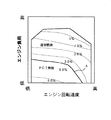
「発明が解決しようとする課題」の欄で説明したように、PCI燃焼と通常燃焼とでは、目標EGR率(最適なEGR率)に比較的大きな隔たりがある。これを図2を用いて説明する。 As described in the section “Problems to be Solved by the Invention”, there is a relatively large difference in target EGR rate (optimal EGR rate) between PCI combustion and normal combustion. This will be described with reference to FIG.
図2は、エンジンの運転状態毎に目標EGR率を定めたマップであり、図のラインAがPCI燃焼と通常燃焼との切換ラインである。即ち、エンジンの運転状態がラインAよりも下側の領域(エンジン負荷が低い領域)ではPCI燃焼を実行し、ラインAから上側の領域では通常燃焼を実行する。 FIG. 2 is a map in which the target EGR rate is determined for each engine operating state, and a line A in the figure is a switching line between PCI combustion and normal combustion. That is, PCI combustion is performed in a region where the engine operating state is lower than line A (region where the engine load is low), and normal combustion is performed in a region above line A.
図から分かるように、PCI燃焼を実行する領域では、目標EGR率が比較的高く(図例では50〜60%)設定される。これは、多量のEGRを実行することで予混合期間を充分に確保し、良好な排気ガス及び燃費を得るためである。PCI燃焼を実行する領域では、エンジン負荷が大きくなる程、目標EGR率が高く設定される。従って、通常燃焼との切換ラインA近傍で目標EGR率は最大(ここでは60%)となる。 As can be seen from the figure, the target EGR rate is set to be relatively high (50 to 60% in the example) in the region where PCI combustion is performed. This is to ensure a sufficient premixing period by executing a large amount of EGR and to obtain good exhaust gas and fuel consumption. In the region where PCI combustion is performed, the target EGR rate is set higher as the engine load increases. Therefore, the target EGR rate becomes maximum (here, 60%) in the vicinity of the switching line A for normal combustion.
一方、通常燃焼を実行する領域では、目標EGR率はPCI燃焼を実行する領域と比較して低く(図例では5〜30%)設定される。これは、酸素不足によるスモークの発生を回避するためである。通常燃焼を実行する領域では、エンジン負荷が低くなる程、目標EGR率が高く設定される。従って、PCI燃焼との切換ラインA近傍で目標EGR率は最大(ここでは30%)となる。本実施形態では、通常燃焼における最大目標EGR率(ここでは30%)は、PCI燃焼における最低目標EGR率(50%)よりも低く設定される。 On the other hand, in the region where normal combustion is performed, the target EGR rate is set lower (5 to 30% in the example) than the region where PCI combustion is performed. This is to avoid the occurrence of smoke due to lack of oxygen. In the region where normal combustion is performed, the target EGR rate is set higher as the engine load becomes lower. Therefore, the target EGR rate becomes maximum (here, 30%) in the vicinity of the switching line A with PCI combustion. In the present embodiment, the maximum target EGR rate (here, 30%) in normal combustion is set lower than the minimum target EGR rate (50%) in PCI combustion.
このように、PCI燃焼の実行領域と通常燃焼の実行領域とで目標EGR率に比較的大きな隔たりがあるため、切換ラインAの両側で目標EGR率が比較的大きく異なることになる。図2に示した例では、切換ラインAの両側で目標EGR率が30%異なっている。従って、エンジンの運転状態がラインAを横切るように変化してPCI燃焼と通常燃焼とを切り換える場合、予混合気のEGR率を短時間で30%も低減又は増加させる必要がある。 Thus, there is a relatively large difference in the target EGR rate between the execution region of PCI combustion and the execution region of normal combustion, so that the target EGR rate is relatively different on both sides of the switching line A. In the example shown in FIG. 2, the target EGR rate is different by 30% on both sides of the switching line A. Therefore, when the engine operating state changes so as to cross the line A to switch between PCI combustion and normal combustion, it is necessary to reduce or increase the EGR rate of the premixed gas by 30% in a short time.
本実施形態のディーゼルエンジンは、PCI燃焼と通常燃焼との切り換え時に、EGR率を迅速に変化させるべく工夫がなされている。 The diesel engine of the present embodiment is devised to change the EGR rate quickly when switching between PCI combustion and normal combustion.
具体的に説明すると、ECU26は、PCI燃焼を実行させる運転領域では、上述した外部EGR装置19及び内部EGR装置29の両方を作動して予混合気のEGR率を目標EGR率に制御する。一方、通常燃焼を実行させる運転領域では、内部EGR装置29によるEGRは実行せずに外部EGR装置29のみを作動して予混合気のEGR率を目標EGR率に制御する(図4(a)参照)。即ち、PCI燃焼と通常燃焼とを切り換える際に、内部EGR装置29の作動・非作動を切り換えることで、EGR率を大きくかつ迅速に変化させることを可能にしている。
More specifically, the
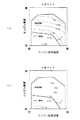
外部EGR装置19及び内部EGR装置29各々の目標EGR率を定めたマップを図3に示す。図3(a)は外部EGR装置19の目標EGR率を定めたマップであり、図3(b)が内部EGR装置29の目標EGR率を定めたマップである。これら両マップに定められた目標EGR率を合計すると、図2のマップに示された目標EGR率と等しくなる。
A map in which the target EGR rate of each of the
図から分かるように、通常燃焼を実行させる領域では、外部EGR装置19の目標EGR率は図2に示した目標EGR率と等しく設定され、内部EGR装置29の目標EGR率は0%とされる。通常燃焼を実行する領域では外部EGR装置19のみを用いてEGR率を制御するからである。
As can be seen from the figure, in the region where normal combustion is performed, the target EGR rate of the
一方、PCI燃焼を実行させる領域では、外部EGR装置19の目標EGR率はエンジンの運転状態にかかわらず一定とされる。この目標EGR率は、通常燃焼を実行する領域における最大目標EGR率(切換ラインA近傍の目標EGR率であり、ここでは30%)とほぼ等しく設定される。そして、内部EGR装置29の目標EGR率は、PCI燃焼で必要とされるEGR率(図2に示す目標EGR率)と、外部EGR装置19の目標EGR率との差、つまり、外部EGR装置19によるEGRでは不足する分のEGR率(ここでは20〜30%)に設定される。
On the other hand, in the region where PCI combustion is executed, the target EGR rate of the
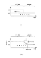
図4(a)を用いて、本実施形態のエンジンにおいてPCI燃焼から通常燃焼に切り換わったときの、燃焼室内の予混合気の実際のEGR率変化を説明する。なお、図4(b)は予混合気のEGR率制御に外部EGR装置19のみを用いるエンジンのEGR率変化を比較のために示したものである。
An actual EGR rate change of the premixed gas in the combustion chamber when switching from PCI combustion to normal combustion in the engine of the present embodiment will be described with reference to FIG. FIG. 4B shows, for comparison, changes in the EGR rate of an engine that uses only the
図中横軸が時間であり、時刻Tにおいてエンジンの運転状態がPCI燃焼実行領域から通常燃焼実行領域に切り換わったとする。 In the figure, it is assumed that the horizontal axis is time, and the operating state of the engine is switched from the PCI combustion execution region to the normal combustion execution region at time T.
時刻Tよりも前、即ち、PCI燃焼を実行しているときは、予混合気のEGR率が比較的高く(図では60%)制御される。 Prior to time T, that is, when PCI combustion is being executed, the EGR rate of the premixed gas is controlled to be relatively high (60% in the figure).
このとき、図4(a)から分かるように、本実施形態のエンジンでは、通常燃焼における最大EGR率分(30%)は外部EGR装置19により達成され、残りの分(30%)が内部EGR装置29により達成される。これに対して、図4(b)のエンジンでは全てのEGR率(60%)が外部EGR装置19により達成される。
At this time, as can be seen from FIG. 4A, in the engine of the present embodiment, the maximum EGR rate (30%) in normal combustion is achieved by the
時刻Tに達してPCI燃焼から通常燃焼に切り換わると、目標EGR率が大きく低下する(ここでは60%→30%)。 When the time T is reached and the PCI combustion is switched to the normal combustion, the target EGR rate is greatly reduced (here, 60% → 30%).
このとき、本実施形態のエンジンでは、図4(a)に示すように、内部EGR装置29によるEGRを全て停止する(30%→0%)。これは、吸気行程における排気弁8の開放期間を実質的にゼロとすることで達成されるため、1サイクルで対応することが可能である。即ち、吸気行程で排気弁を開放しなければ排気ガスが燃焼室10内に戻ることはないので、時間遅れが生じることなく確実かつ迅速に0%となる。一方、外部EGR装置19によるEGR率は通常燃焼に切り換わった直後の目標EGR率(通常燃焼における最大目標EGR率)と等しいので、外部EGR装置19に対する制御量はそのまま維持する。以上の制御により、予混合気の実際のEGR率は時刻Tにて急激に低下し、目標EGR率(30%)と一致する。
At this time, in the engine of the present embodiment, as shown in FIG. 4A, all EGRs by the
これに対して、図4(b)に示したエンジンでは、時刻TにおいてPCI燃焼から通常燃焼に切り換わったときに、外部EGR装置19に対する制御量(EGR弁21の弁開度)を調節してEGR率を低下させる。この場合、EGR弁21から燃焼室10までに吸気経路が存在すること、EGR弁の応答遅れがあること等から、EGR率は図に示すように緩やかに変化していく。この結果、図の領域Bにおいて、目標EGR率と実際のEGR率とに差が生じるため、燃料噴射時期とEGR率とにミスマッチが生じ、排気ガスや燃費が悪化する可能性がある。
On the other hand, in the engine shown in FIG. 4B, when the PCI combustion is switched to the normal combustion at time T, the control amount (the valve opening degree of the EGR valve 21) for the
本実施形態のエンジンでは、PCI燃焼から通常燃焼に切り換わったときに、EGR率を迅速に変化させることが可能であるため、燃焼噴射時期とEGR率とのミスマッチが生じることはなく、排気ガスや燃費が悪化することはない。 In the engine of the present embodiment, the EGR rate can be rapidly changed when switching from PCI combustion to normal combustion, so there is no mismatch between the combustion injection timing and the EGR rate, and the exhaust gas And fuel economy will not deteriorate.
なお、図4に示した例とは逆に、通常燃焼からPCI燃焼に切り換わるときには、外部EGR装置19単独によるEGR率制御から、外部EGR装置19と内部EGR装置29双方によるEGR率制御に切り換えることになる。この場合も、内部EGR装置29によるEGR率の上昇(0→30%)が1サイクルで達成されるため、EGR率を迅速に変化させることができる。
In contrast to the example shown in FIG. 4, when switching from normal combustion to PCI combustion, the EGR rate control by the
ところで、PCI燃焼、通常燃焼に関わらず、常に内部EGR装置29のみを用いて予混合気のEGR率を制御すれば、EGR率をある程度迅速に変化させることができると考えられる。しかしながら、内部EGRは、クーラを通過しない高温の排気ガスを燃焼室10内に戻すものであるため、予混合気の温度が上昇して排気ガスの悪化等を招くおそれがあるというデメリットがある。このため、内部EGR装置29のみを用いてEGR率を制御することは好ましくない。
By the way, it is considered that the EGR rate can be changed to some extent quickly if the EGR rate of the premixed gas is always controlled using only the
本実施形態のエンジンは、外部EGR装置19と内部EGR装置29双方を用いることで、内部EGRのデメリットを最小限に抑えつつ、EGR率の迅速な変化を可能にしたものである。
The engine according to the present embodiment uses both the
本発明は以上説明した実施形態に限定はされない。 The present invention is not limited to the embodiment described above.
例えば、図2及び図3にはEGR率の目標値を定めたマップを示したが、本発明はこの点において限定されず、目標EGR率に対応するEGR装置の制御量(外部EGR装置19のEGR弁21の弁開度、内部EGR装置29の可変バルブ機構28による排気弁8の開放期間等)を定めたマップを作成し、ECU26がそのマップに従って、外部EGR装置19及び内部EGR装置29を制御するようにしても良い。
For example, FIG. 2 and FIG. 3 show maps in which target values of the EGR rate are set, but the present invention is not limited in this respect, and the control amount of the EGR device corresponding to the target EGR rate (of the external EGR device 19) A map defining the valve opening degree of the
また、可変バルブ機構28は、排気弁8の開閉時期を調節する電磁ソレノイドを備えたものに限定されず、排気弁2を開閉するためのカムを複数備え、使用するカムをそれらの中から選択するタイプでも良い。
The
また、内部EGR装置29は、吸気行程で排気弁8を開放するタイプに限定されず、排気行程における排気弁8の開放期間を通常時(内部EGRを実行しないとき)よりも短くして排気ガスの一部を燃焼室10内に残留させるものや、排気行程で吸気弁7を一時的に開放し、排気ガスの一部を吸気ポート5及び吸気管12内に留めておき、吸気行程にてその排気ガスを吸気と共に燃焼室10内に戻すものなど、あらゆるタイプの内部EGR装置が適用可能である。
Further, the
更に、上記実施形態では通常燃焼を実行するときには、パイロット噴射とメイン噴射とを行うとして説明したが、本発明はこの点において限定されない。例えば、メイン噴射のみを行うようにしても良いし、メイン噴射の後に、未燃燃料を燃焼させるためのアフター噴射を実行するようにしても良い。 Furthermore, in the above-described embodiment, it has been described that pilot injection and main injection are performed when normal combustion is performed, but the present invention is not limited in this respect. For example, only main injection may be performed, or after injection for burning unburned fuel may be performed after main injection.
1 エンジン本体
8 可変バルブ機構
9 インジェクタ
19 外部EGR装置
21 EGR弁
26 ECU(制御装置)
29 内部EGR装置
1 Engine Body 8
29 Internal EGR device
Claims (5)
排気通路内の排気ガスの一部をEGR通路を介して吸気通路に還流する外部EGR装置と、
吸気弁又は排気弁の開閉時期を制御して排気ガスの一部を燃焼室に戻す又は残留させる内部EGR装置と、
上記燃料噴射装置、外部EGR装置及び内部EGR装置を制御する制御装置とを備え、 上記制御装置は、所定の運転領域では、燃料を上死点近傍よりも早期に噴射すると共に比較的多量のEGRを実行して燃料の噴射終了後に予混合気が着火する予混合燃焼を実行させ、上記所定の運転領域外では、燃料を上死点近傍で噴射すると共に上記予混合燃焼を実行するときよりも少量のEGRを実行して燃料がその噴射中に着火する通常燃焼を実行させるものであり、
上記制御装置は、上記予混合燃焼を実行させるときは、上記外部EGR装置及び内部EGR装置の両方を用いてEGR率を制御し、上記通常燃焼を実行させるときは、上記内部EGR装置によるEGRは実行せずに上記外部EGR装置のみを用いてEGR率を制御する、
ことを特徴とするディーゼルエンジン。 A fuel injection device for injecting fuel into the combustion chamber;
An external EGR device that recirculates part of the exhaust gas in the exhaust passage to the intake passage via the EGR passage;
An internal EGR device that controls the opening / closing timing of the intake valve or the exhaust valve to return or leave a part of the exhaust gas in the combustion chamber;
And a control device for controlling the fuel injection device, the external EGR device, and the internal EGR device. The control device injects fuel earlier than the vicinity of the top dead center in a predetermined operation region and a relatively large amount of EGR. To perform premixed combustion in which the premixed gas is ignited after the fuel injection is completed. A small amount of EGR is performed to perform normal combustion in which the fuel ignites during its injection,
The control device controls the EGR rate using both the external EGR device and the internal EGR device when performing the premixed combustion, and when performing the normal combustion, the EGR by the internal EGR device is Control the EGR rate using only the external EGR device without executing it,
Diesel engine characterized by that.
The diesel engine according to any one of claims 1 to 3, wherein the internal EGR device shortens an exhaust valve opening period in an exhaust stroke from a normal time.
Priority Applications (4)
| Application Number | Priority Date | Filing Date | Title |
|---|---|---|---|
| JP2004103050A JP4039382B2 (en) | 2004-03-31 | 2004-03-31 | diesel engine |
| EP20050006310 EP1582727B1 (en) | 2004-03-31 | 2005-03-22 | Diesel Engine |
| US11/092,080 US7093590B2 (en) | 2004-03-31 | 2005-03-29 | Diesel engine |
| CNB200510060082XA CN100419240C (en) | 2004-03-31 | 2005-03-31 | Diesel engine |
Applications Claiming Priority (1)
| Application Number | Priority Date | Filing Date | Title |
|---|---|---|---|
| JP2004103050A JP4039382B2 (en) | 2004-03-31 | 2004-03-31 | diesel engine |
Publications (2)
| Publication Number | Publication Date |
|---|---|
| JP2005291002A true JP2005291002A (en) | 2005-10-20 |
| JP4039382B2 JP4039382B2 (en) | 2008-01-30 |
Family
ID=34880023
Family Applications (1)
| Application Number | Title | Priority Date | Filing Date |
|---|---|---|---|
| JP2004103050A Expired - Fee Related JP4039382B2 (en) | 2004-03-31 | 2004-03-31 | diesel engine |
Country Status (4)
| Country | Link |
|---|---|
| US (1) | US7093590B2 (en) |
| EP (1) | EP1582727B1 (en) |
| JP (1) | JP4039382B2 (en) |
| CN (1) | CN100419240C (en) |
Cited By (4)
| Publication number | Priority date | Publication date | Assignee | Title |
|---|---|---|---|---|
| JP2007247447A (en) * | 2006-03-14 | 2007-09-27 | Nissan Motor Co Ltd | NOx emission reduction device |
| JP2007270841A (en) * | 2006-03-31 | 2007-10-18 | Robert Bosch Gmbh | Operation method and control apparatus for internal combustion engine |
| JP2008309031A (en) * | 2007-06-13 | 2008-12-25 | Toyota Motor Corp | Exhaust gas recirculation device for internal combustion engine |
| EP3845755A1 (en) | 2019-12-31 | 2021-07-07 | Kubota Corporation | Engine exhaust manifold |
Families Citing this family (16)
| Publication number | Priority date | Publication date | Assignee | Title |
|---|---|---|---|---|
| JP4165415B2 (en) * | 2004-02-27 | 2008-10-15 | 日産自動車株式会社 | Engine control device |
| US7128063B2 (en) | 2004-07-21 | 2006-10-31 | Gm Global Technology Operations, Inc. | HCCI engine combustion control |
| JP2007051566A (en) * | 2005-08-17 | 2007-03-01 | Hino Motors Ltd | Engine exhaust gas recirculation system |
| US20080087257A1 (en) * | 2006-04-24 | 2008-04-17 | Robinson Barnett J | Internal combustion engine with shared holding tank in cylinder head for elevated expansion ratio |
| US7367290B2 (en) * | 2006-08-24 | 2008-05-06 | Gm Global Technology Operations, Inc. | Diesel combustion mode switching control strategy and model |
| EP1918552B1 (en) * | 2006-10-24 | 2009-08-19 | Honda Motor Co., Ltd. | Internal EGR control system for internal combustion engine |
| US7380547B1 (en) * | 2006-11-17 | 2008-06-03 | Gm Global Technology Operations, Inc. | Adaptive NOx emissions control for engines with variable cam phasers |
| US7810460B2 (en) | 2008-02-15 | 2010-10-12 | Gm Global Technology Operations, Inc. | Adaptive individual dynamic volumetric efficiency optimization for engines with variable cam phasers and variable lift |
| KR101040344B1 (en) * | 2008-09-12 | 2011-06-10 | 서울대학교산학협력단 | Combustion system of vehicle |
| DE112009005130B4 (en) * | 2009-08-07 | 2018-10-04 | Toyota Jidosha Kabushiki Kaisha | INTERNAL COMBUSTION ENGINE WITH SPARK IGNITION |
| US8733320B2 (en) | 2010-04-02 | 2014-05-27 | Ford Global Technologies, Llc | Combustion stability enhancement via internal EGR control |
| US7934486B1 (en) | 2010-04-02 | 2011-05-03 | Ford Global Technologies, Llc | Internal and external LP EGR for boosted engines |
| US9008944B2 (en) * | 2010-05-24 | 2015-04-14 | GM Global Technology Operations LLC | Method and apparatus for controlling operation of an internal combustion engine operating in HCCI combustion mode |
| JP5482716B2 (en) * | 2010-08-20 | 2014-05-07 | マツダ株式会社 | Diesel engine control device and diesel engine control method |
| JP5845817B2 (en) * | 2011-10-31 | 2016-01-20 | スズキ株式会社 | Internal combustion engine |
| DE102012002948A1 (en) * | 2012-02-16 | 2013-08-22 | Man Truck & Bus Ag | Method for operating a self-igniting internal combustion engine |
Family Cites Families (17)
| Publication number | Priority date | Publication date | Assignee | Title |
|---|---|---|---|---|
| JPS5371725A (en) * | 1976-12-09 | 1978-06-26 | Toyota Motor Corp | Exhaust gas re-circulating device for internal combustion engine |
| JPS5813744B2 (en) * | 1977-05-26 | 1983-03-15 | 株式会社日本自動車部品総合研究所 | Internal combustion engine exhaust gas recirculation device |
| JP3617252B2 (en) | 1997-05-29 | 2005-02-02 | いすゞ自動車株式会社 | Compression ignition engine |
| JP3680491B2 (en) * | 1997-06-02 | 2005-08-10 | 日産自動車株式会社 | Control device for internal combustion engine |
| US6125801A (en) * | 1997-11-25 | 2000-10-03 | Mendler; Edward Charles | Lean-burn variable compression ratio engine |
| DE69929743T2 (en) * | 1998-03-03 | 2006-09-21 | Nissan Motor Co., Ltd., Yokohama | Combustion control apparatus for a diesel engine |
| JP3820750B2 (en) | 1998-05-20 | 2006-09-13 | 三菱ふそうトラック・バス株式会社 | diesel engine |
| JP3835142B2 (en) * | 1999-09-07 | 2006-10-18 | 日産自動車株式会社 | Control device for self-ignition / spark ignition internal combustion engine |
| JP3549779B2 (en) * | 1999-09-17 | 2004-08-04 | 日野自動車株式会社 | Internal combustion engine |
| DE10156140B4 (en) * | 2000-11-21 | 2005-12-15 | Mitsubishi Jidosha Kogyo K.K. | Variable valve control |
| ITTO20010660A1 (en) * | 2001-07-06 | 2003-01-06 | Fiat Ricerche | MULTI-CYLINDER DIESEL ENGINE WITH VARIABLE VALVE OPERATION. |
| JP4686942B2 (en) | 2001-09-07 | 2011-05-25 | いすゞ自動車株式会社 | Direct injection diesel engine |
| JP2003232233A (en) * | 2001-12-06 | 2003-08-22 | Nissan Motor Co Ltd | Control device for internal combustion engine |
| JP3846348B2 (en) * | 2002-03-28 | 2006-11-15 | マツダ株式会社 | Diesel engine combustion control system |
| JP4144251B2 (en) * | 2002-05-09 | 2008-09-03 | トヨタ自動車株式会社 | Control of exhaust gas recirculation in internal combustion engines. |
| AT7204U1 (en) * | 2002-12-19 | 2004-11-25 | Avl List Gmbh | METHOD FOR OPERATING A DIRECTLY INJECTING DIESEL INTERNAL COMBUSTION ENGINE |
| CN1212474C (en) * | 2003-02-27 | 2005-07-27 | 上海交通大学 | Humid Air-Diesel Homogeneous Combustion System for Supercharged Diesel Engine |
-
2004
- 2004-03-31 JP JP2004103050A patent/JP4039382B2/en not_active Expired - Fee Related
-
2005
- 2005-03-22 EP EP20050006310 patent/EP1582727B1/en not_active Expired - Lifetime
- 2005-03-29 US US11/092,080 patent/US7093590B2/en not_active Expired - Fee Related
- 2005-03-31 CN CNB200510060082XA patent/CN100419240C/en not_active Expired - Fee Related
Cited By (5)
| Publication number | Priority date | Publication date | Assignee | Title |
|---|---|---|---|---|
| JP2007247447A (en) * | 2006-03-14 | 2007-09-27 | Nissan Motor Co Ltd | NOx emission reduction device |
| JP2007270841A (en) * | 2006-03-31 | 2007-10-18 | Robert Bosch Gmbh | Operation method and control apparatus for internal combustion engine |
| JP2008309031A (en) * | 2007-06-13 | 2008-12-25 | Toyota Motor Corp | Exhaust gas recirculation device for internal combustion engine |
| EP3845755A1 (en) | 2019-12-31 | 2021-07-07 | Kubota Corporation | Engine exhaust manifold |
| US11306687B2 (en) | 2019-12-31 | 2022-04-19 | Kubota Corporation | Engine exhaust manifold |
Also Published As
| Publication number | Publication date |
|---|---|
| EP1582727A2 (en) | 2005-10-05 |
| CN100419240C (en) | 2008-09-17 |
| CN1676909A (en) | 2005-10-05 |
| US7093590B2 (en) | 2006-08-22 |
| US20050217649A1 (en) | 2005-10-06 |
| EP1582727B1 (en) | 2015-05-06 |
| EP1582727A3 (en) | 2007-03-14 |
| JP4039382B2 (en) | 2008-01-30 |
Similar Documents
| Publication | Publication Date | Title |
|---|---|---|
| JP4039382B2 (en) | diesel engine | |
| JP4472932B2 (en) | Engine combustion control device | |
| US7681550B2 (en) | Internal combustion engine | |
| US8670918B2 (en) | Method of controlling automobile-mount diesel engine and the automobile-mount diesel engine | |
| JP4737103B2 (en) | Control unit for gasoline engine | |
| US20100242901A1 (en) | Control of internal combustion engine | |
| JP3849703B2 (en) | Diesel engine control device | |
| JP4161789B2 (en) | Fuel injection control device | |
| JP2018123706A (en) | Internal combustion engine | |
| US10968859B2 (en) | Premixed compression ignition engine and method for controlling premixed compression ignition engine | |
| JP2016031067A (en) | Compression ignition engine control device | |
| JP5333505B2 (en) | Combustion control device | |
| JP4492192B2 (en) | diesel engine | |
| JP2009243295A (en) | Engine intake valve control method and device | |
| US20190093571A1 (en) | Engine control device | |
| JP2016044671A (en) | Control device of compression ignition type engine | |
| KR100512391B1 (en) | Internal combustion engine | |
| JP2008184970A (en) | Control device of gasoline engine | |
| JP2007162544A (en) | Diesel engine control device | |
| JP4461905B2 (en) | Control system for premixed compression self-ignition internal combustion engine | |
| JP2015124738A (en) | Control device of direct injection engine | |
| JP4821248B2 (en) | Combustion switching control system for compression ignition internal combustion engine | |
| JP4123122B2 (en) | Control device for spark ignition engine | |
| JP2006257999A (en) | Internal combustion engine | |
| JP6244881B2 (en) | Control unit for direct injection engine |
Legal Events
| Date | Code | Title | Description |
|---|---|---|---|
| A131 | Notification of reasons for refusal |
Free format text: JAPANESE INTERMEDIATE CODE: A131 Effective date: 20070515 |
|
| A521 | Written amendment |
Free format text: JAPANESE INTERMEDIATE CODE: A523 Effective date: 20070713 |
|
| TRDD | Decision of grant or rejection written | ||
| A01 | Written decision to grant a patent or to grant a registration (utility model) |
Free format text: JAPANESE INTERMEDIATE CODE: A01 Effective date: 20071016 |
|
| A61 | First payment of annual fees (during grant procedure) |
Free format text: JAPANESE INTERMEDIATE CODE: A61 Effective date: 20071029 |
|
| FPAY | Renewal fee payment (event date is renewal date of database) |
Free format text: PAYMENT UNTIL: 20101116 Year of fee payment: 3 |
|
| R150 | Certificate of patent or registration of utility model |
Free format text: JAPANESE INTERMEDIATE CODE: R150 |
|
| FPAY | Renewal fee payment (event date is renewal date of database) |
Free format text: PAYMENT UNTIL: 20101116 Year of fee payment: 3 |
|
| FPAY | Renewal fee payment (event date is renewal date of database) |
Free format text: PAYMENT UNTIL: 20111116 Year of fee payment: 4 |
|
| FPAY | Renewal fee payment (event date is renewal date of database) |
Free format text: PAYMENT UNTIL: 20121116 Year of fee payment: 5 |
|
| FPAY | Renewal fee payment (event date is renewal date of database) |
Free format text: PAYMENT UNTIL: 20121116 Year of fee payment: 5 |
|
| FPAY | Renewal fee payment (event date is renewal date of database) |
Free format text: PAYMENT UNTIL: 20131116 Year of fee payment: 6 |
|
| LAPS | Cancellation because of no payment of annual fees |