JP2005290986A - Fuel management system in cold start fuel passage - Google Patents
Fuel management system in cold start fuel passage Download PDFInfo
- Publication number
- JP2005290986A JP2005290986A JP2003355867A JP2003355867A JP2005290986A JP 2005290986 A JP2005290986 A JP 2005290986A JP 2003355867 A JP2003355867 A JP 2003355867A JP 2003355867 A JP2003355867 A JP 2003355867A JP 2005290986 A JP2005290986 A JP 2005290986A
- Authority
- JP
- Japan
- Prior art keywords
- fuel
- engine
- cold start
- passage
- heater
- Prior art date
- Legal status (The legal status is an assumption and is not a legal conclusion. Google has not performed a legal analysis and makes no representation as to the accuracy of the status listed.)
- Pending
Links
Images


Classifications
-
- Y—GENERAL TAGGING OF NEW TECHNOLOGICAL DEVELOPMENTS; GENERAL TAGGING OF CROSS-SECTIONAL TECHNOLOGIES SPANNING OVER SEVERAL SECTIONS OF THE IPC; TECHNICAL SUBJECTS COVERED BY FORMER USPC CROSS-REFERENCE ART COLLECTIONS [XRACs] AND DIGESTS
- Y02—TECHNOLOGIES OR APPLICATIONS FOR MITIGATION OR ADAPTATION AGAINST CLIMATE CHANGE
- Y02T—CLIMATE CHANGE MITIGATION TECHNOLOGIES RELATED TO TRANSPORTATION
- Y02T10/00—Road transport of goods or passengers
- Y02T10/10—Internal combustion engine [ICE] based vehicles
- Y02T10/40—Engine management systems
Landscapes
- Combined Controls Of Internal Combustion Engines (AREA)
- Electrical Control Of Air Or Fuel Supplied To Internal-Combustion Engine (AREA)
Abstract
【課題】 内燃エンジン用の冷間始動燃料システムの冷間始動通路内に含まれる燃料及び燃料蒸気を消散させるシステムと手順の両方を提供すること。
【解決手段】 作動時に冷間始動燃料通路に燃料を導入する冷間始動燃料噴射装置を有する内燃エンジンの冷間始動燃料通路内の燃料と燃料蒸気を管理するシステム。システムは冷間始動通路内に燃料がある蓋然性を決定するエンジン制御ユニット(ECU)を含む。ECU中にプログラムされた異なる手順が冷間始動通路から燃料を消散するために利用される。これらの手順はエンジンに対するスパーク点火の開始を遅延するステップや、冷間始動燃料噴射装置の作動停止後の所定時間の間、冷間始動燃料噴射装置に関連付けられたヒータを作動状態に維持するステップや、所定時間の間、内燃エンジンの回転を維持するステップや、その他の方策ステップを含む。
【選択図】 図1
PROBLEM TO BE SOLVED: To provide both a system and a procedure for dissipating fuel and fuel vapor contained in a cold start passage of a cold start fuel system for an internal combustion engine.
A system for managing fuel and fuel vapor in a cold start fuel passage of an internal combustion engine having a cold start fuel injection device that introduces fuel into the cold start fuel passage during operation. The system includes an engine control unit (ECU) that determines the likelihood of fuel in the cold start passage. Different procedures programmed in the ECU are utilized to dissipate fuel from the cold start passage. These procedures include the steps of delaying the start of spark ignition for the engine and maintaining the heater associated with the cold start fuel injector in an operating state for a predetermined time after the cold start fuel injector is deactivated. And a step of maintaining the rotation of the internal combustion engine for a predetermined time, and other policy steps.
[Selection] Figure 1
Description
本発明は冷間始動燃料システムを有する内燃エンジンに関し、より詳細にはエンジン停止又は始動中の冷間始動燃料通路内の燃料を消散するシステムに関する。 The present invention relates to an internal combustion engine having a cold start fuel system, and more particularly to a system for dissipating fuel in a cold start fuel passage during engine shutdown or start.
政府規制は自動車用の液体燃料を使用するタイプの内燃エンジンから出る炭化水素、窒素及びその他の排出物の最大量を制限している。しかしながら、内燃エンジンからの炭化水素排出に影響を及ぼす決定的な要因はエンジン点火直後の「冷間始動」フェーズ中の冷えた雰囲気状態から生じる。 Government regulations limit the maximum amount of hydrocarbons, nitrogen and other emissions from internal combustion engines that use liquid fuels for automobiles. However, a decisive factor affecting hydrocarbon emissions from internal combustion engines arises from the cold ambient conditions during the “cold start” phase immediately after engine ignition.
エンジン点火後、典型的にはおよそ二分間続く自動車エンジンに対する冷間始動フェーズの間、自動車用タイプの触媒コンバータは冷えており、従って排気流に含まれる自動車排出物を削減するには非効率的である。更に、エンジンが冷間状態にあるときにエンジン点火を上手く行なうためにしばしば燃料をリッチにする必要がある。 During the cold start phase for an automotive engine, which typically lasts about two minutes after engine ignition, the automotive type catalytic converter is cold and is therefore inefficient to reduce automotive emissions in the exhaust stream. It is. In addition, it is often necessary to enrich the fuel in order to successfully perform engine ignition when the engine is cold.
その結果、自動車内燃エンジンの冷間始動の間、空燃比は理論空燃比燃焼よりずっとリッチであり、典型的には10〜14:1である。しかしながら、政府規制により許容される炭化水素排出物の50%までが最初の20秒間に、つまりエンジン点火直後に生じ得る。更に、これらの政府の排出制限は時の経過と共にますます厳しくなる。 As a result, during the cold start of an automotive internal combustion engine, the air / fuel ratio is much richer than stoichiometric combustion, typically 10-14: 1. However, up to 50% of the hydrocarbon emissions allowed by government regulations can occur in the first 20 seconds, ie immediately after engine ignition. In addition, these government emission limits become increasingly severe over time.
発明の冷間始動中の炭化水素排出物を減らすために、化学量論的又はリーンな燃料チャージ、即ち14.5から16.1の範囲の空燃比でエンジンを始動することが望ましい。エンジン冷間始動中のそのようなリーンな燃料混合を達成し、しかも冷間エンジンの良好な点火を保証するために、温間エンジン状態の間に燃料をエンジンに普通に供給する多点燃料噴射装置の代わりに冷間エンジン始動状態の間にエンジンの燃焼室に燃料チャージを供給する多くの既知の冷間始動燃料システムがこれまでにあった。そのような冷間始動燃料システムの一つは特許文献1に開示されている。 In order to reduce hydrocarbon emissions during the cold start of the invention, it is desirable to start the engine with a stoichiometric or lean fuel charge, i.e., an air-fuel ratio in the range of 14.5 to 16.1. Multi-point fuel injection that normally supplies fuel to the engine during warm engine conditions to achieve such lean fuel blending during engine cold start and to ensure good ignition of the cold engine There have been many known cold start fuel systems to supply fuel charge to the combustion chamber of the engine during cold engine start conditions instead of equipment. One such cold start fuel system is disclosed in US Pat.
これらの既知の冷間始動燃料システムは、典型的には絞り弁の上流にあるエンジンの吸気マニホールドに弁を介して流体接続された一端を有する冷間始動燃料通路を備える。冷間始動燃料噴射装置の第二又は下流の端部は典型的にはエンジン燃焼シリンダの直ぐ近くの吸気マニホールドに対して流体的に開かれている。エンジン用燃料管理システムの制御下にある冷間始動噴射装置は冷間始動燃料通路に燃料を噴射するために冷間始動燃料噴射装置の作動を制御する。エンジン燃焼室に燃料を導入する前に燃料の気化を促進するために典型的には一つ以上のヒータが冷間始動燃料通路の中に、あるいはそれに隣接して収容される。 These known cold start fuel systems typically include a cold start fuel passage having one end fluidly connected through a valve to an intake manifold of the engine upstream of the throttle valve. The second or downstream end of the cold start fuel injector is typically fluidly open to the intake manifold immediately adjacent to the engine combustion cylinder. A cold start injector under control of the engine fuel management system controls the operation of the cold start fuel injector to inject fuel into the cold start fuel passage. One or more heaters are typically housed in or adjacent to the cold start fuel passage to facilitate fuel vaporization prior to introducing fuel into the engine combustion chamber.
これらの既知の冷間始動燃料噴射システムは、エンジンが冷間エンジン点火から、冷間始動燃料噴射装置が作動停止され、代わって燃料が通常の多点燃料噴射装置を介してエンジンに供給される温間エンジン動作状態まで進行する限り、問題なく使用され、エンジンの排気は、また政府の排出規制も満たすことが分っている。反対に、エンジンがエンジン点火の後、温間エンジン動作状態の前に停止される場合に幾つかの問題が生じる。このことが起こるときに、即ち、冷間始動燃料噴射装置がまだエンジンにその燃料蒸気を供給しているのにエンジン停止が生じるときに、燃料蒸気は冷間始動燃料通路に残ることがあり、また実際に残る。実際、エンジン停止がエンジンの冷間始動動作中に生じるとき、幾つかの場合に、液体燃料溜りが冷間始動燃料通路内に生じる。 These known cold start fuel injection systems are such that when the engine is cold engine ignited, the cold start fuel injector is deactivated and fuel is instead supplied to the engine via a conventional multi-point fuel injector. As long as it goes to warm engine operating conditions, it has been used without problems, and it has been found that engine exhaust also meets government emission regulations. Conversely, several problems arise when the engine is shut down after engine ignition and before warm engine operating conditions. When this happens, that is, when the cold start fuel injector is still supplying its fuel vapor to the engine and the engine shuts down, the fuel vapor may remain in the cold start fuel passage, Also actually remains. In fact, when engine shutdown occurs during a cold start operation of the engine, in some cases a liquid fuel puddle occurs in the cold start fuel passage.
なお他のエンジン状態及び/又は故障もまた冷間始動燃料通路内に燃料蒸気又は燃料溜りを生じ得る。例えば、冷間始動ヒータ又は冷間始動燃料噴射装置の故障もまた冷間始動通路内の燃料蒸気または燃料溜りを生じ得る。 Still other engine conditions and / or failures can also cause fuel vapor or puddles in the cold start fuel passage. For example, a failure of the cold start heater or the cold start fuel injector can also cause fuel vapor or a fuel pool in the cold start passage.
冷間始動燃料通路内の燃料蒸気又は液体燃料の存在は不都合にも次ぎに続くエンジン始動の間の炭化水素及び他の有毒排出物の排出を増加し得る。更に、引き続くエンジン始動時に冷間始動燃料通路内に余分な燃料蒸気が残っていたら、エンジンの望ましくないバックファイヤさえ生じ得る。 The presence of fuel vapor or liquid fuel in the cold start fuel passage can undesirably increase the emissions of hydrocarbons and other toxic emissions during subsequent engine starts. In addition, if there is excess fuel vapor remaining in the cold start fuel passage during subsequent engine start-ups, even undesirable backfire of the engine can occur.
早すぎるエンジン停止の場合、即ち冷間動作状態又は他のエンジン状態又はコンポーネントの故障中にエンジンを停止する場合に、冷間始動通路内に含まれる燃料蒸気及び燃料を消散する既知のシステム又は手順はない。 Known systems or procedures for dissipating fuel vapor and fuel contained in the cold start passage in case of premature engine shutdown, i.e. when the engine is shut down during cold operating conditions or other engine conditions or component failures There is no.
本発明は内燃エンジン用の冷間始動燃料システムの冷間始動通路内に含まれる燃料及び燃料蒸気を消散させるシステムと手順の両方を提供する。 The present invention provides both a system and procedure for dissipating fuel and fuel vapor contained in a cold start passage of a cold start fuel system for an internal combustion engine.
簡単に言えば、本発明の方法とシステムは自動車に用いられるタイプの内燃エンジン用に設計される。これらの自動車エンジンは冷間始動燃料噴射装置や冷間始動燃料通路を共に有する冷間始動燃料システムを含む。冷間エンジン動作状態の間、冷間始動燃料噴射装置は、冷間始動燃料通路に燃料を噴射することにより温間エンジン状態中に用いられる多点燃料噴射装置の代わりに燃料をエンジンに供給する。冷間始動燃料通路内のヒータが燃料を気化し、その後この燃料蒸気は所望の方式で内燃エンジンに誘導される。 Briefly, the method and system of the present invention are designed for internal combustion engines of the type used in automobiles. These automobile engines include a cold start fuel system having both a cold start fuel injector and a cold start fuel passage. During cold engine operating conditions, the cold start fuel injector supplies fuel to the engine instead of the multipoint fuel injector used during warm engine conditions by injecting fuel into the cold start fuel passage. . A heater in the cold start fuel passage vaporizes the fuel, which fuel vapor is then directed to the internal combustion engine in the desired manner.
本発明のシステムはエンジン停止又はエンジン始動において冷間始動燃料通路内に燃料がある蓋然性を決定するエンジン制御ユニット(ECU)を含む。冷間始動燃料通路内に燃料がある蓋然性を決定する多くの異なる方法がある。例えば、冷間始動動作状態中のエンジン停止は燃料蒸気が冷間始動燃料通路内にある表れである。 The system of the present invention includes an engine control unit (ECU) that determines the probability that fuel will be in the cold start fuel passage at engine stop or engine start. There are many different ways to determine the probability that fuel will be in the cold start fuel passage. For example, an engine stop during a cold start operating condition is an indication that fuel vapor is in the cold start fuel passage.
同様に、冷間始動燃料ヒータのヒータに流れる電流は、エンジン停止時にエンジン制御回路によりアクセス可能なデジタルメモリーに記憶出来る。その後、引き続くエンジン始動時に、前に記憶されたヒータ電流値はそのヒータ電流値が所定の閾値を超えるかどうかを決定するためにエンジン制御回路により試験される。もしそうではなくてヒータ故障を示したら次のエンジン始動時の冷間始動システムの引き続く使用に際し冷間始動燃料通路内に燃料又は燃料蒸気がある蓋然性がある。 Similarly, the current flowing through the heater of the cold start fuel heater can be stored in a digital memory accessible by the engine control circuit when the engine is stopped. Thereafter, upon subsequent engine start-up, the previously stored heater current value is tested by the engine control circuit to determine whether the heater current value exceeds a predetermined threshold. If this is not the case, there is a possibility that there will be fuel or fuel vapor in the cold start fuel passage for subsequent use of the cold start system at the next engine start.
同様に、冷間始動燃料噴射装置の作動デューティも決定されかつ許容範囲と比較出来る。このデューティが許容範囲外である場合、それは冷間始動噴射装置の故障を表す。次のエンジン始動時の冷間始動システムの動作が冷間始動燃料通路内に燃料又は燃料蒸気を生じる。 Similarly, the operating duty of the cold start fuel injector is also determined and can be compared to an acceptable range. If this duty is out of tolerance, it represents a cold start injector failure. The operation of the cold start system at the next engine start produces fuel or fuel vapor in the cold start fuel passage.
ECUが冷間始動燃料通路内に燃料がある蓋然性を決定する場合、本発明は冷間始動燃料通路から燃料を消散させるように設計された、ECU中にプログラムされた多くの異なる手順を提供する。これらの手順は有毒排出物と炭化水素の発生を最小限にし、また内燃エンジンに起こり得るバックファイヤをも防止する。 When the ECU determines the probability that there will be fuel in the cold start fuel passage, the present invention provides a number of different procedures programmed into the ECU designed to dissipate fuel from the cold start fuel passage. . These procedures minimize the generation of toxic emissions and hydrocarbons and also prevent backfire that can occur in internal combustion engines.
第一の手順において、冷間始動通路内に燃料がある蓋然性がある場合は、冷間始動エンジン動作状態から温間エンジン動作状態への移行後の所定期間、エンジン制御回路が冷間始動ヒータに電力を供給することにより冷間始動ヒータの作動を維持する。冷間始動燃料噴射装置が作動停止された後もヒータを続いて作動することにより、ヒータに残存し得る燃料は全て消散され、エンジンに供給される。 In the first procedure, if there is a possibility that there is fuel in the cold start passage, the engine control circuit switches to the cold start heater for a predetermined period after the transition from the cold start engine operation state to the warm engine operation state. The operation of the cold start heater is maintained by supplying power. By continuing to operate the heater even after the cold start fuel injection device is deactivated, all the fuel that can remain in the heater is dissipated and supplied to the engine.
また別の手順において、冷間始動エンジン動作状態中にエンジンが停止された場合、エンジン停止にも関わらずエンジンを数回転させるように多点燃料噴射システムが所定時間の間作動される。エンジンの継続回転はこうして冷間始動燃料通路に存在し得る全ての燃料蒸気を、燃焼のためにエンジンに誘導する。 In another procedure, when the engine is stopped during the cold start engine operating state, the multipoint fuel injection system is operated for a predetermined time so as to rotate the engine several times despite the engine being stopped. The continued rotation of the engine thus directs all fuel vapors that may be present in the cold start fuel passage to the engine for combustion.
冷間始動燃料通路内に存在する燃料蒸気を消散させるなお更なる手順において、ECUは引き続くエンジン始動状態時に数回転の間エンジンのためのスパーク点火システムの開始を遅延する。そのようなスパークシステムの開始の遅延は冷間始動燃料通路内に含まれる燃料蒸気をエンジン燃焼室に誘導する。そのようなスパークシステムの開始の遅延はまたエンジンのバックファイヤの可能性を減らし、あるいは完全に排除する。更に好ましくは絞り弁が閉位置にあり、エンジンの回転により誘導された空気が冷間始動燃料通路を通るように冷間始動燃料通路から蒸気を消散させる。 In yet a further procedure to dissipate the fuel vapor present in the cold start fuel passage, the ECU delays the start of the spark ignition system for the engine for several revolutions during subsequent engine start conditions. Such a delay in the start of the spark system induces fuel vapor contained in the cold start fuel passage into the engine combustion chamber. Such a delayed start of the spark system also reduces or eliminates the possibility of engine backfire. More preferably, the throttle valve is in a closed position to dissipate steam from the cold start fuel passage so that air induced by engine rotation passes through the cold start fuel passage.
本発明は、添付図と関連して読めば、以下の詳細な説明を参照してよりよく理解されるであろう。その場合、同様の参照文字は幾つかの図面に渡り同様の部分を指す。 The invention will be better understood with reference to the following detailed description when read in conjunction with the accompanying drawings. In that case, like reference characters refer to like parts throughout the several views.
まず図1を参照すれば、内燃エンジン22に使用される燃料供給システム20を図解する(図式的にのみ図解する)。内燃エンジン22は中に空気が誘導される吸気端26を有する吸気マニホールド24を含む。吸気マニホールド24は、通常の方式においては、吸気弁30を介して吸気端26を内燃エンジン22の一つ以上の内燃室28に接続する。
Referring first to FIG. 1, a
やはり図1に言及すれば、冷間始動燃料通路32は吸気マニホールド24に対して開かれたその入口端34を有する。同様に冷間始動燃料通路32はやはり吸気マニホールド24に対して開かれてその入口34の下流にある出口端36を有する。
Still referring to FIG. 1, the cold
好ましくは電子制御された弁である絞り弁38が吸気マニホールド24内で動作するように配置される。絞り弁38は、絞り弁38が吸気マニホールド24を介してその吸気端26から燃焼室28まで直接流れる空気流を実質的に遮る閉位置と、マニホールド24の吸気端26から吸気流が自由に燃焼室28に流れる開位置の間を移動可能である。
A
絞り弁38は、その閉位置にあるときは、冷間始動燃料通路32に対して入口34の直ぐ下流に吸気マニホールド24を横切って延びる。その結果、絞り弁38は、その閉位置にあるときは、誘導された空気流を吸気マニホールド24の吸気端26から冷間始動燃料通路32へ逸らせる。
When in its closed position, the
冷間始動燃料噴射装置40は、電子制御ユニット42(ECU)(図式的にのみ図解する)により作動されるときに冷間始動燃料通路32に燃料を噴射する。更に、ECU42はまた冷間始動燃料噴射装置40からの燃料の気化を促進かつ向上するように通路32に配設されたヒータ44の作動を選択的に制御する。
The cold start
ECUは好ましくはマイクロプロセッサを基本とし、かつ種々のエンジン管理機能を実行するようにプログラムされる。これらの機能は、中でもヒータ44、冷間始動燃料噴射装置40、及び絞り弁38の制御を含む。
The ECU is preferably microprocessor based and programmed to perform various engine management functions. These functions include, among other things, control of the
あるいは空気弁46が冷間始動燃料通路32を通る空気流を制御してもよい。この空気弁46は二値的弁、即ち、開かれているか閉じられているかのどちらかであってもよく、また吸気口34から冷間始動燃料通路32を通る空気流を可変的に制限する調整空気弁でもよい。空気弁46がある場合、ECU42はまたその作動を制御する。
Alternatively, the
なお図1に言及すれば、内燃エンジン22はまた各燃焼室28に関連付けられた多点燃料噴射装置50を含む。多点燃料噴射装置50は、ECU42により作動されるときは噴射装置50から燃焼室28に燃料を噴射する。
Still referring to FIG. 1, the
通常の方式においては、冷間始動動作状態の間、燃料は冷間始動燃料噴射装置40によりエンジン22に供給される。こうして、冷間始動エンジン動作状態の間、ECU42は冷間始動燃料噴射装置40だけでなくヒータ44も作動する。この時、ECU42はまた多点燃料噴射装置50の動作を停止する。冷間始動燃料噴射装置40はヒータ44と共に比較的リーンな空気/燃料混合物を燃焼室28に供給し、それにより通常の内燃エンジン22に関連付けられた触媒コンバータ(図示せず)の加熱に先立つエンジン22から出る有毒排出物を最小限にする。
In the normal manner, fuel is supplied to the
冷間始動燃料システム、即ち冷間始動燃料噴射装置40、ヒータ44及びそれらに関連するコンポーネントはこのように温間エンジン動作状態に達するまで全燃料チャージをエンジン22に供給する。そのようなエンジン冷間始動は典型的には、温間エンジン動作状態とそれにより生じる触媒コンバータの作動が達成されるまでおよそ二分間続く。ECU42は次にエンジンへの燃料供給を冷間始動燃料噴射装置40から多点燃料噴射装置50に移行し、その後、多点燃料噴射装置50がエンジン22への燃料供給全体を提供する。
The cold start fuel system, i.e., the cold
しかしながら、一定の動作状態の間、燃料蒸気、また燃料溜りさえも冷間始動燃料通路32内に生じ得る。例えば、エンジン22に対する冷間始動動作サイクル中のエンジン停止は冷間始動燃料通路32内に燃料蒸気及び/又は燃料溜りを生じ得る。そのような燃料蒸気及び/又は燃料溜りは、本発明により消散されない場合、望ましくない有毒ガスの排出や、エンジン22の引き続く再始動の際にエンジンのバックファイヤさえも生じ得る。
However, during certain operating conditions, fuel vapors or even fuel puddles can occur in the cold
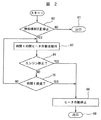
今度は図2を参照すれば、冷間始動動作サイクルの終わりに冷間始動燃料通路32から燃料と燃料蒸気を消散させるためのECU42により用いられる第一の方策が図解される。ステップ60において、ECU42はまず、ECU42が冷間始動燃料噴射装置40を作動停止したかどうかを決定することにより冷間始動動作サイクルの終了を決定する。もしそうなら、ステップ60は次にステップ62に進む。そうでなければ、ステップ60はステップ61においてこの手順から出る。
Referring now to FIG. 2, the first strategy used by the
ステップ62においてECU42はヒータ44の作動を維持し、次にステップ64に分岐する。ステップ64においてECU42はエンジン停止が生じたかどうかを決定する。もしそうなら、ステップ64はステップ66に分岐し、ヒータ44を作動停止する。そのようなヒータ44の作動停止はバッテリー電力を節約するためには望ましい。ステップ66は次にステップ68に進み、図2に図解される消散方策を終了する。
In
逆に、エンジン停止が生じず、その代わり多点燃料噴射装置50が燃料をエンジンに供給する温間エンジン動作状態に進んだと仮定すれば、ステップ64は代わりにステップ70に分岐する。ステップ70は、冷間始動燃料通路32に含まれる如何なる燃料も完全に気化させるのに必要な時間tが経過したかどうかを決定する。時間tはエンジンの大きさ、エンジン速度、周囲温度及びその他の要因により二秒と一分の間で変動する。もしそうでなければ、ステップ70はステップ62に戻り、そこで上記の手順が何度も反復される。逆に時間tが経過したら、ステップ70は代わってステップ66に分岐し、そこでヒータ44を作動停止し、次にステップ68においてルーチンから出る。
Conversely, assuming that the engine has not stopped and instead the
このようにして、ECUは、冷間始動通路内の燃料の気化とその燃焼室への誘導を確実に行なうことにより冷間始動燃料通路から燃料と燃料蒸気を効率的に消散させる。 In this way, the ECU efficiently dissipates fuel and fuel vapor from the cold start fuel passage by reliably vaporizing the fuel in the cold start passage and guiding it to the combustion chamber.
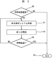
今度は図1と3を参照すれば、冷間始動燃料通路内の燃料を消散させるなお更なる手順が図解されるが、それは冷間エンジン動作サイクル中のエンジン停止により生じた冷間始動燃料通路32内の燃料溜りを消散させるのに特に有用である。 Referring now to FIGS. 1 and 3, a still further procedure for dissipating fuel in the cold start fuel passage is illustrated, which is a cold start fuel passage caused by engine shutdown during the cold engine operating cycle. It is particularly useful for dissipating the fuel puddle in 32.
ステップ80において、ECU42はまず冷間始動動作サイクル中にエンジン停止が生じたかどうかを決定する。冷間始動動作サイクル中の停止を決定するためにECU42はどのような通常手段を用いてもよい。しかしながら好ましくは、ECU42は冷間エンジン動作状態の兆候として冷間始動燃料噴射装置40の作動を利用するが、温度センサー、冷間始動燃料システムの始動からの経過時間、エンジン点火からの経過時間等の他の手段を代わりに採用してもよい。いずれの場合にも、冷間始動エンジン動作状態の間の停止が検出されたら、ステップ80はステップ82に分岐する。
In
ステップ82において、多点燃料噴射装置50がエンジン停止後に所定時間の間、好ましくは10秒以下の間、燃焼室28に燃料を供給するようにECU42は多点燃料噴射システムを作動する。この動作状態の間、多点燃料噴射装置50により燃焼室28に供給された燃料は燃焼室に燃料/空気の継続する誘導を保証する。吸気マニホールド24を通る空気流が冷間始動燃料通路32を通って燃焼室28での燃焼のために冷間始動燃料通路32内の燃料と燃料蒸気を消散させることを保証するために、ステップ82はステップ84に分岐し、そこではECU42が絞り弁38を閉じて吸気マニホールド24を通る空気流を冷間始動燃料通路32に逸らせる。ステップ84は次にステップ86に分岐する。
In
ステップ86において、ECU42は、多点燃料噴射システムに対する作動の所望時間が経過したかどうかを決定する。もしそうでなければ、ステップ86はステップ82に分岐し、上記のステップを何度も反復する。逆に、その時間が経過したら、ステップ86はステップ88において出る。同様に、冷間エンジン停止が起こらなかった場合は、ステップ80はまたステップ88に分岐し、手順を終了する。
In
今度は図1と4を参照すれば、冷間始動エンジン動作状態中の冷間始動燃料通路32内の燃料蒸気を消散させるなお更なる手順が図解される。ステップ100において、ECU42は冷間始動ヒータ44の電流を決定する。ヒータ電流を決定するためにはECU42にアナログ信号を供給するシャント等のどのような通常手段も利用出来る。同様に、データをECUによる便利なフォーマットに変換するためにECU42は通常のアナログ/デジタル変換器を用いる。ステップ100は次にステップ102に分岐する。
Referring now to FIGS. 1 and 4, a still further procedure for dissipating fuel vapor in the cold
ステップ102において、ECU42はステップ100において決定されたヒータ電流を閾値と比較する。更にこの閾値は適切に動作する冷間始動ヒータ44を表している。閾値より少ないヒータ電流は不適切に機能する冷間始動ヒータ44を表している。そのような不適切に動作する冷間始動ヒータ44が訂正されないままであれば、冷間始動燃料通路32内の過剰な燃料と燃料蒸気を生じることになる。
In
ヒータ電流が閾値より小さい場合、ステップ102はステップ104に分岐し、そこではECUは冷間始動燃料噴射装置40を作動停止することにより冷間始動システムを作動停止する。ステップ104は次にステップ106に進み、そこでは多点燃料噴射システムが作動されてエンジン22を継続動作させる。ステップ106は次にステップ108に分岐し、また場合により冷間始動燃料システムの故障を使用者に警告してもよい。ステップ108は次にステップ110においてこの手順を出る。
If the heater current is less than the threshold, step 102 branches to step 104, where the ECU deactivates the cold start system by deactivating the cold
逆に、ヒータ電流が、ヒータ44が適切に動作していることを表す、閾値より大きい場合は、ステップ102はステップ110に分岐して手順を終了する。
Conversely, if the heater current is greater than the threshold value indicating that the
ECU42がヒータ電流44の故障を決定するときは常にECU42はこの故障の兆候をデータとして記憶する。その後に、エンジン22の引き続く再始動時に、ヒータ44の修理までECU42は冷間始動燃料噴射システムを自動的に作動停止する。そうする場合、冷間始動燃料通路32内の燃料蓄積は引き続くエンジン再始動時に最小限になり、こうして冷間始動燃料通路32から出る燃料を消散させる。
Whenever the
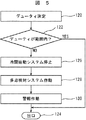
今度は図1と5を参照すれば、冷間始動燃料噴射装置40の故障から生じ得る冷間始動燃料通路32内の燃料を消散させる更なる手順が図解される。ステップ120において、冷間始動サイクル中に、ECU42は冷間始動燃料噴射装置40のデューティを決定する。ステップ120は次にステップ122に分岐する。
Referring now to FIGS. 1 and 5, a further procedure for dissipating fuel in the cold
ステップ122においてECU42は、ステップ120において決定された冷間始動燃料噴射装置40のデューティは冷間始動燃料噴射装置40の正常動作を示す所定範囲と比較する。デューティが許容範囲内にある場合、ステップ122はステップ124に分岐し、ルーチンを出る。
In
逆に、冷間始動燃料噴射装置40に対するデューティが許容範囲外である場合、ステップ122は代わりにステップ126に分岐し、そこではECU42は冷間始動燃料システムを停止する。ステップ126は次にステップ128に進み、多点噴射燃料システムを作動してエンジン22の継続的な動作を可能にさせる。ステップ128は次にステップ130に進み、場合により多点燃料噴射装置の故障を使用者に警告を発する。ステップ130は次にステップ124に進み、ルーチンを出る。図5に記載された方法に従って多点燃料噴射装置の故障を検知したら、ECUはこの情報をデータとして記憶する。エンジン22が引き続き再始動したら、ECUは冷間始動燃料システムの作動を防止し、こうして冷間始動燃料噴射装置40が修理されるまで冷間始動燃料通路32内の燃料蒸気の蓄積を防止する。
Conversely, if the duty for the cold
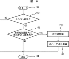
今度は図1と6を参照すれば、エンジン始動の際に冷間始動燃料通路内の燃料蒸気を消散させるなお更なる手順が図解される。ステップ150において、手順は変数等を作り出し、ステップ152に進む。
Referring now to FIGS. 1 and 6, a still further procedure for dissipating fuel vapor in the cold start fuel passage during engine start is illustrated. In
ステップ152において、ECU42はエンジン始動状態が生じたかどうかを決定する。もしそうでないなら、ステップ152はステップ154に分岐し手順を出る。そうでない場合は、ステップ152はステップ156に分岐する。
In
ステップ156において、ECU42は冷間始動燃料通路32内に燃料蒸気又は燃料溜りがある蓋然性さえも決定する。前に議論したように、そのような燃料は冷間始動システムのコンポーネントの故障、又は以前の冷間始動エンジン動作状態中のエンジン停止から生じ得る。どの場合にも、ECU42が冷間始動燃料通路内に燃料がある蓋然性がないと決定したら、ステップ156はステップ154に分岐し、この手順から出る。そうでない場合は、ステップ156はステップ160に分岐する。
In
ステップ160において、絞り弁38が電子制御されることを前提としてECU42は場合により、絞り弁を閉じてもよい。このように絞り弁38を閉じることにより、吸気マニホールド24に誘導された空気流は冷間始動燃料通路に逸らされる。ステップ160は次にステップ162に進み、そこでECU42はエンジンを数回転するためのスパーク点火システムの開始を遅延する。そうする際に、ECU42はエンジンにより誘導された空気が冷間始動燃料通路32に逸らされ、それにより冷間始動燃料通路32内の潜在する燃料が燃焼室に誘導されることにより消散されることを保証する。この手順の部分としてスパーク点火システムの遅延はまた冷間始動燃料通路32内の燃料蒸気によるエンジン始動時のエンジンバックファイヤの可能性を排除する。
In
以上のことから、本発明は冷間始動燃料通路内に過剰燃料がある蓋然性を決定し、またその過剰燃料を消散させる手段を提供することが分る。そのような過剰燃料は冷間始動燃料システムのコンポーネントの欠陥の結果として、あるいは冷間始動サイクル中のエンジンの停止から生じ得る。 From the above, it can be seen that the present invention provides a means for determining the probability of excess fuel in the cold start fuel passage and for dissipating the excess fuel. Such excess fuel may arise as a result of a defective component of the cold start fuel system or from an engine shutdown during the cold start cycle.
発明の好ましい実施例においてECU42は冷間始動燃料システムだけでなく多点燃料噴射システムの動作を制御するけれども、もちろん、別の制御回路が冷間始動システムに利用されても、また第二の制御回路が多点噴射システムの制御に用いられてもよいことは言うまでもない。どちらの場合も、好ましくは、ECU42は単一コンポーネントであろうがマルチコンポーネントであろうが、記憶されたコンピュータプログラムを実行するだけでなく冷間始動燃料システムの状態に関するデータを記憶出来る能力を有するプログラマブルマルチプロセッサを備える。
In the preferred embodiment of the invention, the
更に、燃料消散手順の何れかまた全ては単独で、あるいは他と組合せて用いてもよい。 Further, any or all of the fuel dissipation procedures may be used alone or in combination with others.
私の発明を述べたが、添付された特許請求の範囲により定められる発明の精神から逸脱することなく、発明が関係する当業者にはそれに対する多くの変形が明らかになるであろう。 Having described my invention, many variations thereto will become apparent to those skilled in the art to which the invention pertains without departing from the spirit of the invention as defined by the appended claims.
22…内燃エンジン、24…吸気マニホールド、26…吸気端、28…燃焼室、30…吸気弁、32…冷間始動燃料通路、34…入口端、36…出口端、38…絞り弁、40…冷間始動燃料噴射装置、42…電子制御ユニット、44…ヒータ、46…空気弁、50…多点燃料噴射装置。
DESCRIPTION OF
Claims (33)
Priority Applications (1)
| Application Number | Priority Date | Filing Date | Title |
|---|---|---|---|
| JP2003355867A JP2005290986A (en) | 2003-10-16 | 2003-10-16 | Fuel management system in cold start fuel passage |
Applications Claiming Priority (1)
| Application Number | Priority Date | Filing Date | Title |
|---|---|---|---|
| JP2003355867A JP2005290986A (en) | 2003-10-16 | 2003-10-16 | Fuel management system in cold start fuel passage |
Publications (1)
| Publication Number | Publication Date |
|---|---|
| JP2005290986A true JP2005290986A (en) | 2005-10-20 |
Family
ID=35324222
Family Applications (1)
| Application Number | Title | Priority Date | Filing Date |
|---|---|---|---|
| JP2003355867A Pending JP2005290986A (en) | 2003-10-16 | 2003-10-16 | Fuel management system in cold start fuel passage |
Country Status (1)
| Country | Link |
|---|---|
| JP (1) | JP2005290986A (en) |
Cited By (3)
| Publication number | Priority date | Publication date | Assignee | Title |
|---|---|---|---|---|
| KR101394854B1 (en) * | 2012-12-28 | 2014-05-13 | 현대자동차주식회사 | Heater assembly for cold starting improvement of flex fuel vehicle |
| KR20140078424A (en) * | 2012-12-17 | 2014-06-25 | 현대자동차주식회사 | Cold start system for ethanol vehicle and method thereof |
| KR101490907B1 (en) | 2013-06-07 | 2015-02-06 | 현대자동차 주식회사 | Cold starting device and cold starting method for vehicle |
-
2003
- 2003-10-16 JP JP2003355867A patent/JP2005290986A/en active Pending
Cited By (3)
| Publication number | Priority date | Publication date | Assignee | Title |
|---|---|---|---|---|
| KR20140078424A (en) * | 2012-12-17 | 2014-06-25 | 현대자동차주식회사 | Cold start system for ethanol vehicle and method thereof |
| KR101394854B1 (en) * | 2012-12-28 | 2014-05-13 | 현대자동차주식회사 | Heater assembly for cold starting improvement of flex fuel vehicle |
| KR101490907B1 (en) | 2013-06-07 | 2015-02-06 | 현대자동차 주식회사 | Cold starting device and cold starting method for vehicle |
Similar Documents
| Publication | Publication Date | Title |
|---|---|---|
| JP3788424B2 (en) | Engine failure diagnosis device | |
| US6736103B2 (en) | System for management of fuel in a cold start fuel passageway | |
| US6647961B2 (en) | Internal combustion engine and control method of the same | |
| JP2005127316A (en) | Fuel injection control method of lpi engine, and its device | |
| RU2669112C1 (en) | Engine fuel supply method and device | |
| BR102013007132A2 (en) | Method for controlling a fuel injector, system configured to control an internal combustion engine, and controller | |
| US6543431B2 (en) | System for air-fuel ratio control | |
| JP2001234829A (en) | Fuel injection system for internal combustion engine | |
| US6318334B1 (en) | Method for sparking engine cylinders after fuel shutdown for reduced emissions | |
| JP2004028046A (en) | Starting control device for internal combustion engine | |
| KR0140367B1 (en) | Engine fueled with mixed fuel and operation control method thereof | |
| JP2005290986A (en) | Fuel management system in cold start fuel passage | |
| Kim et al. | Development of HMC LPI Mono-Fuel Vehicle | |
| KR20040041421A (en) | Lpi system for protecting injector leakage | |
| JP2591309B2 (en) | Fuel vapor emission suppression device | |
| KR20200124112A (en) | Fuel injection quantity correction method for vehicle | |
| JP2004346813A (en) | LPG fuel engine and method of operating LPG fuel engine | |
| JP4269948B2 (en) | Fuel injection control device | |
| JP4757994B2 (en) | Fuel supply device | |
| JP7555677B2 (en) | Control device for internal combustion engine | |
| JP4052521B2 (en) | Control device for internal combustion engine | |
| JP3539259B2 (en) | Heater control device for air-fuel ratio sensor | |
| JP2011236815A (en) | Control device of internal combustion engine | |
| KR102214579B1 (en) | Apparatus for controlling fuel injection time and method thereof | |
| JPH0618069Y2 (en) | Engine starter |
Legal Events
| Date | Code | Title | Description |
|---|---|---|---|
| A621 | Written request for application examination |
Free format text: JAPANESE INTERMEDIATE CODE: A621 Effective date: 20060203 |
|
| RD02 | Notification of acceptance of power of attorney |
Free format text: JAPANESE INTERMEDIATE CODE: A7422 Effective date: 20060203 |
|
| A131 | Notification of reasons for refusal |
Free format text: JAPANESE INTERMEDIATE CODE: A131 Effective date: 20081021 |
|
| A02 | Decision of refusal |
Free format text: JAPANESE INTERMEDIATE CODE: A02 Effective date: 20090303 |