JP2005290977A - Rigid ribbon having sine wave shape - Google Patents
Rigid ribbon having sine wave shape Download PDFInfo
- Publication number
- JP2005290977A JP2005290977A JP2005084635A JP2005084635A JP2005290977A JP 2005290977 A JP2005290977 A JP 2005290977A JP 2005084635 A JP2005084635 A JP 2005084635A JP 2005084635 A JP2005084635 A JP 2005084635A JP 2005290977 A JP2005290977 A JP 2005290977A
- Authority
- JP
- Japan
- Prior art keywords
- ribbon
- shape
- wavelength
- concave
- vertices
- Prior art date
- Legal status (The legal status is an assumption and is not a legal conclusion. Google has not performed a legal analysis and makes no representation as to the accuracy of the status listed.)
- Withdrawn
Links
- 239000002023 wood Substances 0.000 abstract description 23
- 230000008859 change Effects 0.000 abstract description 5
- 239000007787 solid Substances 0.000 abstract description 5
- 239000000463 material Substances 0.000 description 8
- 238000005452 bending Methods 0.000 description 7
- 238000001035 drying Methods 0.000 description 5
- 239000011121 hardwood Substances 0.000 description 4
- 238000010276 construction Methods 0.000 description 3
- 238000010438 heat treatment Methods 0.000 description 3
- 230000000007 visual effect Effects 0.000 description 3
- 238000010030 laminating Methods 0.000 description 2
- 238000000034 method Methods 0.000 description 2
- 230000004048 modification Effects 0.000 description 2
- 238000012986 modification Methods 0.000 description 2
- 229920001169 thermoplastic Polymers 0.000 description 2
- 239000004416 thermosoftening plastic Substances 0.000 description 2
- 229910000831 Steel Inorganic materials 0.000 description 1
- 239000000853 adhesive Substances 0.000 description 1
- 238000004026 adhesive bonding Methods 0.000 description 1
- 230000001070 adhesive effect Effects 0.000 description 1
- 238000007605 air drying Methods 0.000 description 1
- 230000000712 assembly Effects 0.000 description 1
- 238000000429 assembly Methods 0.000 description 1
- 210000002421 cell wall Anatomy 0.000 description 1
- 230000000295 complement effect Effects 0.000 description 1
- 239000002131 composite material Substances 0.000 description 1
- 230000006835 compression Effects 0.000 description 1
- 238000007906 compression Methods 0.000 description 1
- 238000005516 engineering process Methods 0.000 description 1
- 239000003822 epoxy resin Substances 0.000 description 1
- 239000000835 fiber Substances 0.000 description 1
- 239000003292 glue Substances 0.000 description 1
- 239000008241 heterogeneous mixture Substances 0.000 description 1
- 230000001788 irregular Effects 0.000 description 1
- 239000002648 laminated material Substances 0.000 description 1
- 238000004519 manufacturing process Methods 0.000 description 1
- 230000013011 mating Effects 0.000 description 1
- 229910052751 metal Inorganic materials 0.000 description 1
- 239000002184 metal Substances 0.000 description 1
- 150000002739 metals Chemical class 0.000 description 1
- 229920003023 plastic Polymers 0.000 description 1
- 229920000647 polyepoxide Polymers 0.000 description 1
- 230000009467 reduction Effects 0.000 description 1
- 238000007493 shaping process Methods 0.000 description 1
- 239000010959 steel Substances 0.000 description 1
- 229920003002 synthetic resin Polymers 0.000 description 1
- 239000000057 synthetic resin Substances 0.000 description 1
- 229920001187 thermosetting polymer Polymers 0.000 description 1
- 239000002699 waste material Substances 0.000 description 1
- XLYOFNOQVPJJNP-UHFFFAOYSA-N water Substances O XLYOFNOQVPJJNP-UHFFFAOYSA-N 0.000 description 1
Images
Classifications
-
- B—PERFORMING OPERATIONS; TRANSPORTING
- B27—WORKING OR PRESERVING WOOD OR SIMILAR MATERIAL; NAILING OR STAPLING MACHINES IN GENERAL
- B27M—WORKING OF WOOD NOT PROVIDED FOR IN SUBCLASSES B27B - B27L; MANUFACTURE OF SPECIFIC WOODEN ARTICLES
- B27M3/00—Manufacture or reconditioning of specific semi-finished or finished articles
-
- B—PERFORMING OPERATIONS; TRANSPORTING
- B27—WORKING OR PRESERVING WOOD OR SIMILAR MATERIAL; NAILING OR STAPLING MACHINES IN GENERAL
- B27D—WORKING VENEER OR PLYWOOD
- B27D1/00—Joining wood veneer with any material; Forming articles thereby; Preparatory processing of surfaces to be joined, e.g. scoring
Landscapes
- Life Sciences & Earth Sciences (AREA)
- Engineering & Computer Science (AREA)
- Wood Science & Technology (AREA)
- Forests & Forestry (AREA)
- Manufacturing & Machinery (AREA)
- Mechanical Engineering (AREA)
- Rod-Shaped Construction Members (AREA)
Abstract
Description
本発明は、構造および非構造の適用に向けられ、波状の硬質リボンの構成およびその形成方法に関する。 The present invention is directed to structural and non-structural applications and relates to the construction of wavy rigid ribbons and methods of forming the same.
露出する建築アーチ、柱および梁には、構造的な信頼性と共に、視覚的な魅力が要求される。それらは巨大な直径の、堅い老木から切り出されるか、あるいは寸法の小さな木材を積層してこれらを一体に接着して製造される。これらの製品のあるものは、外観を改善するために化粧張りを施される。視界から遮られる構造要素は、視覚的な外観を懸念することなく設計できる。 Exposed architectural arches, columns and beams require visual appeal along with structural reliability. They are cut from large diameter, hard old wood or manufactured by laminating small sized wood and gluing them together. Some of these products are veneered to improve their appearance. Structural elements that are blocked from view can be designed without concern for visual appearance.
アーチのための木工製品の場合のように、木材を曲線構造に形作る必要があるとき、多量の材木資源の浪費を伴って、固体(ソリッド)木材から機械加工により作られる。これに代えて、鋸歯の引目や斧の切り口から素材に多量の目減りを与えて形成される帯状の薄い材木片を積層して形成することができる。このように、従来技術の欠点は、完成品の重量増加、材木資源の効率の悪い利用を招き、美的刺激の少ないものが多かった。 When timber needs to be shaped into a curved structure, as in the case of wood products for arches, it is machined from solid timber, with a waste of timber resources. Instead, it can be formed by laminating thin strips of timber formed by applying a large amount of reduction to the material from saw blades or ax cuts. As described above, the disadvantages of the prior art are that the weight of the finished product is increased and the timber resources are inefficiently used, and there are many aesthetic stimuli.
したがって、視覚的に興味を引き、軽量であり、小寸法の木材から構成することができ、ソリッドあるいは積層構造の木製品と同様な寸法の木材のほぼ半分以下の木材の使用で、いかなる寸法および形状に製造し得る柱、支柱、アーチ、梁の形式の製品の必要性が存在していた。その製品は、また1次元以上の次元で曲げることができるものである。さらに、木骨作りの構造、階段、手すり、家具およびボートのような応用品の直線あるいは曲線要素として、強い視覚衝撃を与えるべく、木材、鋼、複合材料およびその他の材料の規格品との置き換えの必要性が存在していた。 Therefore, it is visually interesting, lightweight, can be constructed from small timber, and any size and shape with the use of less than half of timber similar to solid or laminated wood products There was a need for products in the form of pillars, columns, arches and beams that could be manufactured. The product can also be bent in one or more dimensions. In addition, as a straight or curved element in applications such as timber construction, stairs, handrails, furniture and boats, it can be replaced with standard wood, steel, composite and other materials to give a strong visual impact. There was a need.
本発明の実施例は、断面あるいは全体がほぼ正弦波形の少なくとも一つの硬質リボンを有することを特徴とする。各リボンは、第1の端および第2の端(これにより長手方向軸が決まり)を有する本体部分と、第1および第2の主面と、2つの横側面とを備える。前記リボンの性質は単純なものから複雑なものまで変えることができ、従来のものを本発明に用いることができる。 An embodiment of the invention is characterized in that it has at least one rigid ribbon that is substantially sinusoidal in cross-section or overall. Each ribbon includes a body portion having a first end and a second end (which defines a longitudinal axis), first and second major surfaces, and two lateral sides. The properties of the ribbon can vary from simple to complex and conventional ones can be used in the present invention.
当業者にとっては、従来の正弦波形の称呼が基準系に応じて任意に選択することができることは明らかであり、例を挙げれば、波形の頂点は、基準系によって反転し、またその逆も同様である。したがって、本発明およびその実施例の記載に当たって、従来の称呼に関する固有の基準系での論点であることを考慮すべきである。 It will be apparent to those skilled in the art that the designation of a conventional sinusoidal waveform can be arbitrarily selected depending on the reference system, for example, the top of the waveform is inverted by the reference system and vice versa. It is. Therefore, in describing the present invention and its embodiments, it should be considered that this is an issue in a specific reference system regarding conventional naming.
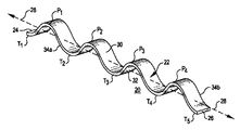
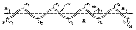
ここに開示した各実施例は、複数の凸部すなわち頂点 (Pn) を含む。凹部すなわち底点 (Tn) が各頂点を相互に分ける。したがって、各頂点は2つの近接する底点を伴い、また各底点は2つの近接する頂点を伴う。添え字「n」は、任意の始点に関する前記頂点あるいは底点の特定の位置および番号を指し、文脈によっては全ての位置を総括的に示す。正弦波形の記載を用いる場合、前記波形の一端から開始するとき、その表記は、次のとおりである。P1、T1、P2、T2、P3、T3、P4 …。この数列は、また次のように定義することができる。Pn、Tn、Pn+1、Tn+1、Pn+2、Tn+2、Pn+3 …。ここで、「n」は、任意の整数(この場合は「1」)である。波長「λ」は任意の隣り合う2つの頂点間あるいは2つの底点間の距離である。波形部分の振幅は、一般的に、ある頂点あるいは底点のいずれかの点から標準レベルすなわち平衡レベル迄の距離である。 Each embodiment disclosed herein includes a plurality of protrusions or vertices (P n ). A recess or base (T n ) separates each vertex from each other. Thus, each vertex has two adjacent vertices, and each base point has two adjacent vertices. The subscript “n” refers to the specific position and number of the vertex or base point for an arbitrary starting point, and collectively indicates all positions depending on the context. When using the sinusoidal description, when noting from one end of the waveform, the notation is as follows: P 1 , T 1 , P 2 , T 2 , P 3 , T 3 , P 4 . This sequence can also be defined as: P n , T n , P n + 1 , T n + 1 , P n + 2 , T n + 2 , P n + 3 . Here, “n” is an arbitrary integer (in this case, “1”). The wavelength “λ” is a distance between any two adjacent vertices or two bottom points. The amplitude of the waveform portion is generally the distance from either a vertex or bottom point to the standard or equilibrium level.
一組の実施例では、単純な正弦波形部分を有するリボンが開示されているが、この波形の振幅および波長の両者を前記リボンの長さ方向へその全体にわたって変化させることができる。さらに、一部あるいは全ての頂点に接する仮想線をほぼ凸形、凹形、波状形あるいは線形とすることができる。同様に、一部あるいは全ての底点に接する仮想線をほぼ凸形、凹形、波状形あるいは線形とすることができる。さらに、前記したように、前記リボンに少なくとも1つのフランジ要素を組み込むことができ、該フランジ要素は複数の前記頂点のうちの一つに結合することができる。構造的な応用では、少なくとも一つの前記フランジ要素の有無に拘わらず(以下に説明するように、少なくとも一つの前記フランジ要素を設けることにより、多くの利点がもたらされるが)、圧縮負荷を前記主面あるいは前記横側面に向けることができる。 In one set of embodiments, a ribbon having a simple sinusoidal portion is disclosed, but both the amplitude and wavelength of this waveform can be varied throughout the length of the ribbon. Furthermore, the imaginary line in contact with some or all of the vertices can be substantially convex, concave, wavy, or linear. Similarly, imaginary lines that touch some or all of the bottom points can be substantially convex, concave, wavy, or linear. Further, as described above, at least one flange element can be incorporated into the ribbon, and the flange element can be coupled to one of the vertices. In structural applications, with or without at least one flange element (as will be described below, providing at least one flange element provides a number of advantages), the compressive load is applied to the main load. Can be directed to the surface or the lateral surface.
他の一組の実施例では、前記リボンは、該リボンの両端間、好ましくは頂点Pnおよび底点Tn間で、長手方向軸線に沿って少なくとも180°のねじれを含む。さらに、この組の他の実施例は、長手方向軸線に沿って180°の整数倍、すなわち360°、540°、270°…のねじれを含む。そのような全ての実施例において、前記した変更が適用可能である。また、この他の組の実施例では、前記リボンは、所定のいかなる点の断面でも正弦波形を示すということはないが、全体的に正弦波形を示す。 In another set of embodiments, the ribbon comprises a twist of at least 180 ° along the longitudinal axis between the ends of the ribbon, preferably between the apex P n and the base point T n . In addition, other examples of this set include an integral multiple of 180 ° along the longitudinal axis, ie, 360 °, 540 °, 270 °... In all such embodiments, the changes described above are applicable. Also, in this other set of embodiments, the ribbon does not exhibit a sinusoidal waveform at the cross section of any given point, but exhibits an overall sinusoidal waveform.
前記した2つの組をさらに結合した実施例、すなわち、さらに付加的な実施例は、前記2つの組の異種の混合である。したがって、全体の波状の形態の一部を第1の組の実施例とし、波状形態の他の部分を第2の組の実施例とすることができる。付加的な実施例は、前記横側面が平面ではなく、または前記リボンの長手方向軸線が線形ではなく、すなわち曲線であり、複数のリボンが積層状に連結されている。 An embodiment in which the two sets described above are further combined, ie, an additional embodiment, is a heterogeneous mixture of the two sets. Therefore, a part of the entire wavy form can be the first set of examples and the other part of the wavy form can be the second set of examples. In additional embodiments, the lateral sides are not planar, or the longitudinal axis of the ribbon is not linear, i.e. curved, and a plurality of ribbons are connected in a stack.
本発明の前記した特徴および他の特徴は、添付の図面を参照しての以下の詳細な説明の記載から理解できるであろう。 The foregoing and other features of the present invention will be understood from the following detailed description with reference to the accompanying drawings.
以下の記載は、当業者が本発明の実施および利用を可能とするように開示されている。好ましい実施例への種々の変更は、当業者にとって明らかであり、ここに記載の全体的な原理は、本書に添付の特許請求の範囲に規定されている本発明の精神および範囲から逸脱することなく、他の実施例に適用することができる。したがって、本発明は、図示の実施例に限定されることはなく、ここに開示した原理および特徴の範囲に矛盾しない最も広い範囲に存在する。 The following description is disclosed to enable any person skilled in the art to make and use the invention. Various modifications to the preferred embodiment will be apparent to those skilled in the art and the general principles described herein may depart from the spirit and scope of the invention as defined in the claims appended hereto. However, the present invention can be applied to other embodiments. Accordingly, the present invention is not limited to the illustrated embodiments, but exists in the widest scope consistent with the scope of the principles and features disclosed herein.
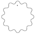
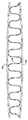
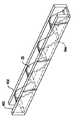
同様な部分には同様な番号が付された図面、特に、図1および図2を参照するに、第1の組の実施例が遠近法で示されている。この組で開示された全ての実施例には、リボン20が示されている。リボン20は、第1の端24および第2の端26(これにより長手方向軸線28が決まれる)により境界を与えられた本体部分22と、第1の主面30および第2の主面32と、横側面34aおよび34bとを有する。図示の例では、リボン20は、頂点P1−4および底点T1−5を含み、これらはほぼ互いに対称的であり、換言すればリボン20が反転あるいは回転しても実質的にその外観が変化しない。
Referring to the drawings in which like parts are similarly numbered, in particular FIGS. 1 and 2, a first set of embodiments is shown in perspective. In all embodiments disclosed in this set, a
リボン20は、好ましくは積層木材あるいは圧縮木材で構成され、該圧縮木材はデンマークのターストルップに在るダンクス テクノロジスク インスティチュートが所有する特許の方法によって製造され、この特許は米国特許第5,190,088号で開示され、参考として本明細書に組み込まれている。この製法では、20−25%の好ましい含水量を有する硬質木材を加熱し、柔らかく(可塑化)し、その結果、長手方向へ圧縮することができる。加熱は、蒸気あるいは無線周波数(RF)を用いて行われ、前記硬質木材の温度を好ましくは約100℃に高める。適正な加熱の後、前記硬質木材は、約10分間、特殊な横型液圧プレスで長手方向に約20−25%圧縮される。この軸線圧縮の結果、軸方向の繊維細胞壁が折り畳まれ、前記硬質木材は曲げられ、あるいはその後の曲げのために、曲げが保存される。一旦曲げられると、その成形木材は、空気乾燥、輻射熱乾燥、対流熱乾燥、RF乾燥あるいはマイクロ波乾燥のような種々の手段を用いて曲げることができる。前記木材の曲げは、人手による曲げ、クランプあるいは万力を用いる曲げ、水圧あるいはエアシリンダを用いたプレス曲げ、例えばローラを用いた連続曲げ、および熱と(加熱は必要とされる圧力を低減させ乾燥を促進させる)圧力とを用いた曲げのような種々の曲げを用いて行うことができる。 Ribbon 20 is preferably composed of laminated wood or compressed wood, which is produced by the method of a patent owned by Danks Technology Institute in Tarstrup, Denmark, which is patented in US Pat. No. 5,190. No. 088, which is incorporated herein by reference. In this production process, hard wood having a preferred water content of 20-25% can be heated and softened (plasticized) and consequently compressed in the longitudinal direction. Heating is performed using steam or radio frequency (RF) to increase the temperature of the hardwood, preferably to about 100 ° C. After proper heating, the hard wood is compressed about 20-25% in the longitudinal direction with a special horizontal hydraulic press for about 10 minutes. As a result of this axial compression, the axial fiber cell walls are folded and the hard wood is bent, or the bending is preserved for subsequent bending. Once bent, the shaped wood can be bent using various means such as air drying, radiant heat drying, convection heat drying, RF drying or microwave drying. The bending of the wood includes manual bending, bending using a clamp or a vise, press bending using hydraulic pressure or an air cylinder, for example, continuous bending using a roller, and heat (heating reduces the pressure required). Can be performed using various bends, such as bends with pressure (which promotes drying).
本実施例では、圧縮木材の厚板が図示のリボンを形成すべく曲げ形成を受けている。これに代えて、薄い複数の帯状の木材を曲げて積層を形成すべく接着することができる。再び厚板の前記木材の形付けに用いられた手段がデザイン選択に考慮される。要求されるすべては所望の幾何的特徴を含む最終的な構造による。この実施例では、波長「λ」および正弦波形曲線は相対的に変化せず、頂点から頂点までの距離は前記リボンの長手方向の全体にわたってほぼ一様であり、各頂点を結ぶ接線は各底点を接続する接線にほぼ平行である。 In this embodiment, the compressed wood plank is bent to form the ribbon shown. Alternatively, a plurality of thin strips of wood can be bent and bonded to form a stack. Again, the means used for shaping the wood of the plank is taken into account in the design choice. All that is required depends on the final structure including the desired geometric features. In this example, the wavelength “λ” and the sinusoidal curve do not change relatively, the distance from the apex to the apex is substantially uniform throughout the length of the ribbon, and the tangent line connecting the apexes is It is almost parallel to the tangent line connecting the points.
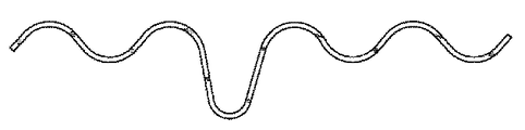
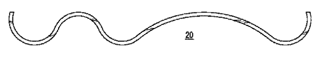
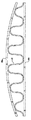
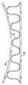
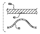
前記したように、リボン20の性質を変更することが可能であり、所望に変更することができる。変更は、図3に示すようにリボン20の振幅を変えること、図4に示すようにリボン20の波長「λ」を変えること、図6−10に示すように上方の頂点および下方の底点の接線を変えること、すなわち頂点の接線を凸形または凹形にし、底点の接線を凸形または凹形にし、あるいは前記2つの形状を組み合わせること、および図6−11および14に示されているように、リボン20の種々の部分にフランジ40を付加することが含まれる。熟練した技術者達は、単位リボンに、該リボンが用いられる応用に応じて、これら変更の一つ以上を組み合わせることができることを理解できるだろう。
As described above, the properties of the
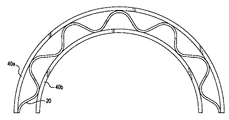
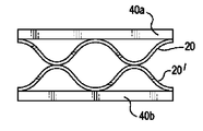
図6−11に示されているように頂点Pnおよび底点Tnあるいは図14に示されているように横側面34に、それぞれ固定的に取り付けられた少なくとも一つのフランジを組み込むことは、構造用に、特に有効である。フランジ40aおよび40bを頂点Pnおよび底点Tnにそれぞれ固定することにより、トラスと同様な、および/またはI型梁のような構造を構築することができる。これにより、頂点Pnに作用する圧縮負荷を低減し、リボン20の長手方向のそりを低減することができる。同様に、2つのフランジ40cおよび40dを横側面34aおよび34bに固定することにより、ある程度のそりを抑制することができる。また、当業者は、ある応用には一つのフランジで十分であり、また前記リボンの全ての側面に取り付けて該リボンを取り囲むことにより、トーションボックス構造を作ることができることが理解できよう。さらに、前記フランジは、透明プラスチックのような合成樹脂材料を含む所望の材料で構成することができる。
Incorporating at least one flange each fixedly attached to the apex P n and the bottom point T n as shown in FIGS. 6-11 or the lateral side 34 as shown in FIG. Especially effective for construction. The
リボン20へのフランジ40の取付けは、木ねじ、ボルトナット組立体、無頭釘、釘、だぼ等の機械的な留め具、エポキシ樹脂、膠のような接着剤の使用あるいはそれらの組み合わせとすることができる。さらに、各フランジのリボンとの接触点に凹所を形成することができ、これによりこれら2つの構成要素間の結合強度を高めることができる。図13に示すように、凹所42は、少なくとも頂点Pnの一部を相補的に受け入れるべく、フランジ40に形成されている。これにより、横方向負荷すなわち剪断に対する抵抗を増大させることができる。
The attachment of the flange 40 to the
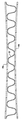
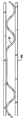
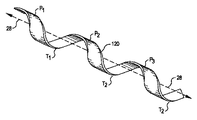
図15は、第2の組の実施例を遠近法で示す。第1の組の実施例とは異なり、第2の組は、前記リボンの短軸が前記リボンに沿った全ての点で平行である必要がないことを示す。ここでは、リボン120は、回転しており、すなわちその長手方向軸線にそってねじれており、全体的に正弦波形を維持している。リボン20と同様に、圧縮木材あるいは積層木材により構成されている。
FIG. 15 shows a second set of examples in perspective. Unlike the first set of embodiments, the second set indicates that the minor axis of the ribbon need not be parallel at every point along the ribbon. Here, the
任意のPnおよびTn間の回転すなわちねじれの数は、デザインの選択事項であるが、リボン120が構造物の用途に用いられる場合、すべての表面に共通な、負荷に耐える単一平面を有することが望ましい。例えば、図15に示すリボン120が各頂部および各底部で平面部分を有し、置換例(図示せず)は前記リボンの横側面に平面部分を有する。
The number of rotations or twists between any P n and T n is a matter of design choice, but when the
リボン120に与えられる回転すなわちねじれは、規則正しくする必要がなく(リボン120のセグメント毎の回転すなわちねじれ数は不規則とすることができ)、また、同じ方向とする必要はない(一つの波長またはその一部に、一方向の回転すなわちねじれを与え、残部に逆方向の回転すなわちねじれを与えることができる)。ほとんどの場合、フランジ要素あるいは他の平面部材が用いられていれば、あるいは前記リボンが構造的応用に用いられていれば、前記リボンに適正な合わせ面を維持することが望まれる。これは、必ずしも必要ではないが、前記リボンの前記接触面がすべての図示の例に示されていると同様な平面状であることを意味する。
The rotation or twist imparted to the
前記した全ての実施例では、圧縮木材あるいは積層木材が用いられている。しかしながら、当業者にとっては、前記リボンおよびフランジの構成のために置換材料を用いることができることが明らかであろう。特に、いかなる形状への曲げが可能な非記憶材料が、実行可能な置換材料として考えられる。これらは、多くの金属、積層木材、ソリッド木材および(熱可塑性および熱硬化性)プラスチックを含む。しかしながら、圧縮木材、ソリッド木材および熱可塑性プラスチックあるいは積層材料、特に積層木材のような実質的に均質な材料を用いることが最良の結果をもたらす。 In all the embodiments described above, compressed wood or laminated wood is used. However, it will be apparent to those skilled in the art that replacement materials may be used for the ribbon and flange configuration. In particular, non-memory materials that can be bent into any shape are considered viable replacement materials. These include many metals, laminated wood, solid wood and (thermoplastic and thermoset) plastic. However, it is best to use substantially homogeneous materials such as compressed wood, solid wood and thermoplastics or laminated materials, especially laminated wood.
さらに、第1および第2の組の実施例を組み合わせて構成することができる。複数のリボンを付加構成を形成すべく種々の方法で組み合わせることができる。図12は、2列すなわち積み重ね形態を示し、第2のリボンがその底点を第1のリボンの頂点に接触させており(オフセットの積み重ね)、これに代えて、第2のリボンに入れ子式(整合した積み重ね)に積層された第1のリボンを含む積層リボンを有する形態(図示せず)とすることができる。さらに他の組み合わせは、セグメント構成を含むことができ、すなわち、ほぼ正弦波の形態の一つを例えば図11に示すような他の幾何学的形態によって遮断することができる。 Further, the first and second sets of embodiments can be combined. Multiple ribbons can be combined in various ways to form additional configurations. FIG. 12 shows a two-row or stacked configuration, with the second ribbon having its bottom point in contact with the apex of the first ribbon (offset stacking), instead of being nested in the second ribbon. It can be in a form (not shown) having a laminated ribbon that includes a first ribbon laminated in a (aligned stack). Still other combinations can include segment configurations, i.e., one of the approximately sinusoidal forms can be blocked by other geometrical forms as shown, for example, in FIG.
20、20′、120 リボン
22 本体部分
24、26 端
28 長手方向軸線
34a、34b 横側面
30、32 主面
40a、40b フランジ
42 凹所
Pn 頂点
Tn 底点
20, 20 ', 120 Ribbon 22
Claims (34)
第1および第2の主面と、前記幅(W)にほぼ等しい幅および前記長さ(L)にほぼ等しい長さを有する第1および第2の横側面と、
前記第1および第2の端間にあって全体的に正弦波形を形成する複数の頂点(Pn)および底点(Tn)とを含む装飾用または構造用の要素。 A unit ribbon comprising a body portion having a length (L) between a first end and a second end, whereby a longitudinal axis, width (W) and thickness (D) are determined;
First and second main surfaces; first and second lateral sides having a width substantially equal to the width (W) and a length substantially equal to the length (L);
A decorative or structural element comprising a plurality of vertices (P n ) and bottom points (T n ) between the first and second ends and forming a generally sinusoidal waveform.
第1の端と第2の端との間に長さ(L)を有する本体部分を備え、これにより長手方向軸線、幅(W)および厚さ(D)が決まる単位リボンと、
第1および第2の主面と、前記幅(W)にほぼ等しい幅および前記長さ(L)にほぼ等しい長さを有する第1および第2の横側面と、
前記第1および第2の端間にあって全体的に正弦波波形を形成する複数の頂点(Pn)および底点(Tn)と、
前記要素に固定的に取り付けられ、前記複数の頂点の少なくともいくつか、前記底点の少なくともいくつか、または前記横側面の少なくとも一方に接する第1のフランジとを含む、装飾用または構造用の要素。 A decorative or structural element,
A unit ribbon comprising a body portion having a length (L) between a first end and a second end, whereby a longitudinal axis, width (W) and thickness (D) are determined;
First and second main surfaces; first and second lateral sides having a width substantially equal to the width (W) and a length substantially equal to the length (L);
A plurality of vertices (P n ) and bottom points (T n ) between the first and second ends and forming an overall sinusoidal waveform;
A decorative or structural element fixedly attached to the element and comprising a first flange that contacts at least some of the plurality of vertices, at least some of the bottom points, or at least one of the lateral sides .
第1および第2の主面と、前記幅(W)にほぼ等しい幅および前記長さ(L)にほぼ等しい長さを有する第1および第2の横側面と、
前記第1および第2の端間にあって全体的に正弦波波形を形成する複数の頂点(Pn)および底点(Tn)とを含み、
前記リボンは前記第1の端と前記第2の端との間に少なくとも一つの長手方向に沿ってのねじれをもつ、装飾用または構造用の要素。 A unit ribbon comprising a body portion having a length (L) between a first end and a second end, whereby a longitudinal axis, width (W) and thickness (D) are determined;
First and second main surfaces; first and second lateral sides having a width substantially equal to the width (W) and a length substantially equal to the length (L);
A plurality of vertices (P n ) and bottom points (T n ) between the first and second ends and forming an overall sinusoidal waveform,
The decorative or structural element, wherein the ribbon has at least one longitudinal twist between the first end and the second end.
Applications Claiming Priority (1)
| Application Number | Priority Date | Filing Date | Title |
|---|---|---|---|
| US10/817,199 US20050247005A1 (en) | 2004-04-01 | 2004-04-01 | Rigid ribbon having overall sinusoidal-like waveform shape |
Publications (1)
| Publication Number | Publication Date |
|---|---|
| JP2005290977A true JP2005290977A (en) | 2005-10-20 |
Family
ID=34887779
Family Applications (1)
| Application Number | Title | Priority Date | Filing Date |
|---|---|---|---|
| JP2005084635A Withdrawn JP2005290977A (en) | 2004-04-01 | 2005-03-23 | Rigid ribbon having sine wave shape |
Country Status (6)
| Country | Link |
|---|---|
| US (1) | US20050247005A1 (en) |
| EP (1) | EP1582324A1 (en) |
| JP (1) | JP2005290977A (en) |
| AU (1) | AU2005201220A1 (en) |
| CA (1) | CA2500692A1 (en) |
| NZ (1) | NZ539067A (en) |
Families Citing this family (2)
| Publication number | Priority date | Publication date | Assignee | Title |
|---|---|---|---|---|
| FR2922920A1 (en) * | 2007-10-31 | 2009-05-01 | Woold Sas Soc Par Actions Simp | WOOD-BASED BEAM COMPRISING AN ONDULATING SHELL FORMING A SHOCK ABSORBER |
| US20230132253A1 (en) * | 2020-06-15 | 2023-04-27 | Fritz Kohl Gmbh & Co, Kg | Wood composite block, translucent wood veneer and method for producing the same |
Family Cites Families (26)
| Publication number | Priority date | Publication date | Assignee | Title |
|---|---|---|---|---|
| US25704A (en) * | 1859-10-04 | James molyneux | ||
| US759899A (en) * | 1902-08-08 | 1904-05-17 | William A Lynch | Composite board. |
| US836960A (en) * | 1906-03-07 | 1906-11-27 | Frederick A Cammann | Wall-tie. |
| US1236829A (en) * | 1915-02-16 | 1917-08-14 | Harlow J Evans | Sheathing for wooden buildings. |
| US1179773A (en) * | 1915-07-01 | 1916-04-18 | Stollsteimer Mfg Company | Refrigerator-wall construction. |
| US1780739A (en) * | 1930-04-12 | 1930-11-04 | Berg Joseph | Insulating block |
| US2215241A (en) * | 1939-01-23 | 1940-09-17 | Weston Paper And Mfg Company | Insulating board and plaster base |
| US2196781A (en) * | 1939-04-13 | 1940-04-09 | Felix H Saino | Fire wall, bulkhead, and panel |
| US2446893A (en) * | 1943-10-06 | 1948-08-10 | Spalding A G & Bros Inc | Laminated construction |
| US2397388A (en) * | 1944-03-18 | 1946-03-26 | Lockheed Aircraft Corp | Building construction |
| US2576530A (en) * | 1947-01-08 | 1951-11-27 | Leon E Medal | Panel construction |
| US2641029A (en) * | 1950-02-24 | 1953-06-09 | Fred H Trimmer | Coupling means and trim for laminated building units |
| US3217845A (en) * | 1961-02-06 | 1965-11-16 | Crown Zellerbach Corp | Rigidified corrugated structure |
| DE1164627B (en) * | 1961-10-19 | 1964-03-05 | Hanns Hess | Solid wall girders with wooden belts and one or more plywood webs that are wavy in plan |
| US3186896A (en) * | 1962-05-09 | 1965-06-01 | American Colloid Co | Moisture impervious panel |
| GB1097452A (en) * | 1963-11-21 | 1968-01-03 | Yoshitoshi Sohda | Wall and roof components for buildings or like constructions |
| US3819466A (en) * | 1973-06-18 | 1974-06-25 | Care Inc | Reinforced and insulating building panel |
| SE7802441L (en) * | 1978-03-03 | 1979-09-04 | Wennstrom Elof | THREE RULE |
| US4255477A (en) * | 1978-10-24 | 1981-03-10 | Holman John A | Artificial board of lumber |
| US4400927A (en) * | 1980-07-14 | 1983-08-30 | Iowa State Research Foundation, Inc. | Method of forming a skeletal dome structure in situ |
| FR2651035A1 (en) * | 1989-08-18 | 1991-02-22 | Air Liquide | PROCESS FOR THE PRODUCTION OF NITROGEN BY DISTILLATION |
| DK418389D0 (en) * | 1989-08-24 | 1989-08-24 | Teknologisk Inst | PROCEDURE FOR USE BY CUTTING WOODEN COATS AND APPARATUS FOR USE IN EXERCISING THE PROCEDURE |
| US5256467A (en) * | 1990-05-14 | 1993-10-26 | Nihon Dimple Carton Co., Ltd. | Heat-insulating corrugated cardboards and method for making them |
| US5097646A (en) * | 1991-01-16 | 1992-03-24 | Stewart Lamle | Compound building member |
| US5339577A (en) * | 1992-12-08 | 1994-08-23 | Snyder Darryl L | Laminated non-combustible board for forming ductwork and headers |
| DE4411663A1 (en) * | 1994-04-05 | 1995-10-12 | Christian Frode Blyt | Wooden component |
-
2004
- 2004-04-01 US US10/817,199 patent/US20050247005A1/en not_active Abandoned
-
2005
- 2005-03-14 CA CA002500692A patent/CA2500692A1/en not_active Abandoned
- 2005-03-22 AU AU2005201220A patent/AU2005201220A1/en not_active Abandoned
- 2005-03-23 JP JP2005084635A patent/JP2005290977A/en not_active Withdrawn
- 2005-03-29 NZ NZ539067A patent/NZ539067A/en unknown
- 2005-03-31 EP EP05102555A patent/EP1582324A1/en not_active Withdrawn
Also Published As
| Publication number | Publication date |
|---|---|
| AU2005201220A1 (en) | 2005-10-20 |
| EP1582324A1 (en) | 2005-10-05 |
| NZ539067A (en) | 2006-12-22 |
| US20050247005A1 (en) | 2005-11-10 |
| CA2500692A1 (en) | 2005-10-01 |
Similar Documents
| Publication | Publication Date | Title |
|---|---|---|
| US6519912B1 (en) | Composite wood products | |
| JP6509214B2 (en) | Core layer with wood elements, in particular wood elements having a wave-like structure | |
| US11208806B2 (en) | Lightweight construction board containing wave-like elements | |
| WO2009030132A1 (en) | A jointless lengthened bamboo section material and a method thereof | |
| CA2762210C (en) | Sandwich structured construction element | |
| CN105751342A (en) | Plate material, solid wood composite floor base material and column material made from branch materials and round rod materials, and manufacturing method | |
| US5948198A (en) | Method of producing a corrugated construction unit | |
| JP2005290977A (en) | Rigid ribbon having sine wave shape | |
| CN102561168A (en) | Bamboo plywood beam structure | |
| US10668699B2 (en) | Multilayer composite having corrugated wooden elements | |
| WO2015036654A1 (en) | Honeycomb structure | |
| JP2005131966A (en) | Timber-laminated top board | |
| EP0755330B1 (en) | A corrugated construction unit and a method for producing the same | |
| US20110005642A1 (en) | Method for Making Braided Structures | |
| JP2007015114A (en) | Woody panel using small diameter wood and its manufacturing method | |
| JP2002210709A (en) | Laminated lumber using bamboo and its manufacturing method | |
| CN205799771U (en) | A kind of wood-based plate and plate core thereof | |
| RU2144459C1 (en) | Veneer | |
| WO2023144794A2 (en) | Composite resilient plate and its use | |
| BG105827A (en) | Method for the manufacture of thin-walled shell module and supporting element made according to the method | |
| JPH106312A (en) | Wood-based material and method for producing the same | |
| JP2004090567A (en) | Member for landing of stairs | |
| NZ578749A (en) | Building element made of laminated veneer lumber (LVL) |
Legal Events
| Date | Code | Title | Description |
|---|---|---|---|
| A300 | Application deemed to be withdrawn because no request for examination was validly filed |
Free format text: JAPANESE INTERMEDIATE CODE: A300 Effective date: 20080603 |