JP2005290973A - Electronic device equipped with opening/closing door - Google Patents
Electronic device equipped with opening/closing door Download PDFInfo
- Publication number
- JP2005290973A JP2005290973A JP2005068734A JP2005068734A JP2005290973A JP 2005290973 A JP2005290973 A JP 2005290973A JP 2005068734 A JP2005068734 A JP 2005068734A JP 2005068734 A JP2005068734 A JP 2005068734A JP 2005290973 A JP2005290973 A JP 2005290973A
- Authority
- JP
- Japan
- Prior art keywords
- door plate
- door
- open position
- electronic device
- bearing
- Prior art date
- Legal status (The legal status is an assumption and is not a legal conclusion. Google has not performed a legal analysis and makes no representation as to the accuracy of the status listed.)
- Withdrawn
Links
- 239000000463 material Substances 0.000 description 3
- 238000013459 approach Methods 0.000 description 2
- 238000012937 correction Methods 0.000 description 2
- 239000000428 dust Substances 0.000 description 2
- 230000000694 effects Effects 0.000 description 2
- 230000007423 decrease Effects 0.000 description 1
- 230000006866 deterioration Effects 0.000 description 1
- 230000002787 reinforcement Effects 0.000 description 1
- 238000000926 separation method Methods 0.000 description 1
Images


Landscapes
- Hinges (AREA)
- Casings For Electric Apparatus (AREA)
Abstract
Description
この発明は、AVジャックなどの接続端子や押圧ボタン等の操作部を配置した収納部の前面側において、開閉可能なドアを備えた電子機器に関する。 The present invention relates to an electronic device including a door that can be opened and closed on the front side of a storage unit in which an operation unit such as a connection terminal such as an AV jack or a push button is arranged.
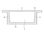
特許文献1には、DVDプレーヤーなどの電子機器の蓋体を開けようとするとき半開きの開放位置に係止する構造が開示されている。しかし、特許文献1はドアを開放位置に係止するという効果については類似しているが、その目的と構造については本発明と異なることから、以下に本発明が関わる技術的目的を達成するための従来技術について説明する。映像表示装置や映像記録再生装置等に代表される電子機器を構成するフロントパネルには、図3に示すように、他の電子機器との信号の入出力を行うために必要な接続端子や、電子機器を操作するために必要な押圧ボタン等の操作部がフロントパネルの外観面より奥側へ入り込んだ凹み部1に配置されている。この凹み部1は、5面の内壁、すなわち側壁11、14、奥壁15、上面壁13、及び底面壁12により構成されており、図13乃至図14に示すように、凹み部1の対向する側壁11及び14は、後述する機能を果たすために奥壁15に向かってその離間距離が漸次小さくなるように傾斜した状態で形成されている。すなわち、奥壁15に向かって側壁11及び14は互いに接近するように距離が小さくなっている。尚、奥壁15と対向する他の1方向は開口部16となっており、この凹み部1には開口部16を塞ぐためのドア板2が取り付けられている。凹み部1の開口部16側にドア板2を取り付けることで、ドア板2を閉鎖した時には電子機器の前面に配置した接続端子や操作部が凹み部1に収納された状態となり、ドア板2を開放した時には凹み部1に配置された接続端子や操作部が電子機器の外部に露出して、他の電子機器との間で信号の入出力を行うためのケーブルの接続や、或いは電子機器の操作が可能となる。このようなドア板2を電子機器のフロントパネルに取り付けた構造については、電子機器の外観意匠を向上する為に従来より多用されている。
図11は、従来の電子機器の凹み部1におけるドア板2の取り付け構造を一部切欠き分解して示しており、開口部16に対してほぼ垂直に伸びる凹み部1の側壁11には、ピボット軸となる円筒状の支柱40が開口部16とほぼ平行に突出している。ドア板2にはブラケット20が設けられ、このブラケット20は凹み部1の側壁11から突出した支柱40の円筒表面41を挟み込む湾曲したブラケット受容部材21、21を有する。ブラケット受容部材21、21は支柱40の円筒表面41と接触するブラケット受容面22、22を有し、ドア板2のブラケット20が支柱40に取り付けられた時、円筒表面41とブラケット受容面22、22とが接触する。又、このドア板2に形成したブラケット20とフロントパネルの凹み部1に形成した支柱40との取り付け構造は、凹み部1の側壁11側のみならず、対向する側壁14側にも設けられている。ドア板2はこの支柱40とブラケット20によって凹み部1の開口部16側に枢動自在に取り付けられる。
FIG. 11 shows an exploded structure of the
図12(A)及び図12(B)は、ドア板が閉鎖位置と開放位置にある時の支持部近傍の状態を示している。図12(A)ではドア板2が閉鎖位置にある状態を示しており、ユーザーなどがドア板2を開けて凹み部1に配置している接続端子に他の電子機器との間で信号の入出力を行うためのケーブルの接続、或いは電子機器の操作を行うための押圧ボタン等の操作部にアクセスするとき、ドア板2を矢印の方向に手で回動させると、図12(B)に示すようにドア板2が支持部40を支点として回動し、ドア板2が開放位置にある状態となる。ドア板2はこの開放位置で凹み部1の側壁11と14との接近する側壁の内壁に摩擦係合し、この摩擦係合によりドア板2は開放位置に保持され、指を離してもこの摩擦を克服する力を図12(B)の矢印方向に与えない限り、ドア板2が閉鎖位置となる図12(A)の状態へは枢動しない。従って、開放位置となる図12(B)の状態から摩擦を克服する大きさの力をドア板2に与えることにより、ブラケット20が支柱40を支点に枢動されて閉鎖位置となる。
FIGS. 12A and 12B show a state in the vicinity of the support portion when the door plate is in the closed position and the open position. FIG. 12 (A) shows a state in which the
しかし、従来のドアの開閉機構を持つ電子機器には、次のような欠点があった。
(イ)経年使用でドア板2と凹み部1の対向する側壁11、14との摩擦係合によって、ドア板2と側壁11、14に傷が付くために電子機器の外観を損なう。
(ロ)経年使用によりドア板2と凹み部1の対向する側壁11、14との摩擦で材料が削られ、係合が緩くなり、開状態を保持できなくなる。
(ハ)凹み部1に設けた支柱40の外径よりもブラケット受容部材21、21の内径を小さくしないと、摩擦によるドア板2の開状態保持ができない為、ドア板2の取り付け時において内径を小さくしたブラケット受容部材21、21の取り付けが困難となり、作業性が著しく低下する。
(ニ)ブラケット受容部材21、21の内径を小さくすることで、ドア板2の取り付け時にブラケット受容部材21、21が折れるなどの不具合が生じる危険性がある。
(ホ)ブラケット受容部材21、21の内径を小さくすることで、ドア板2の開閉動作時においてブラケット20に負荷がかかり、ドア板2の開閉がスムーズに行なえないことによる品質の低下が生じる。
(ヘ)「(ハ)」及び「(ニ)」の不具合を解消するために、支柱40の円筒表面41を受容するブラケット受容部材21、21の開き(支柱40との非接触部分)を大きくした場合、円筒表面41とブラケット受容面22、22との接触面積が減少して十分な摩擦保持ができない可能性がある。
(ト)「(ハ)」〜「(ヘ)」の不具合が生じないように、ブラケット受容部材21、21の内径寸法及び支柱40の外形寸法を選定する場合、現物の嵌合状態をチェックして繰り返し修正が必要となり、寸法が厳密になることに加え、高価な金型の修正費用及び余分な修正時間がかかる。
However, conventional electronic devices having a door opening / closing mechanism have the following drawbacks.
(A) The
(B) The material is scraped by friction between the
(C) Since the
(D) By reducing the inner diameters of the
(E) By reducing the inner diameters of the
(F) In order to eliminate the problems “(c)” and “(d)”, the opening of the
(G) When selecting the inner diameter dimension of the
本発明は、上記の従来技術による電子機器の欠点を解決することを課題とする。 An object of the present invention is to solve the drawbacks of the above-described conventional electronic devices.
本発明の課題は、電子機器の接続端子及び/又は操作部を収納する凹み部を形成するための内壁と、当該接続端子及び/又は操作部にユーザーがアクセスできる開口部と、当該開口部を閉鎖することができるドア板と、当該ドア板を当該開口部に対して開放位置と閉鎖位置との間で枢動自在に支持し、かつ当該ドア板を開放位置に係止することができるピボット支持手段とからなる開閉ドアを備えることにより解決される。
さらに、本発明の課題は、上記の開閉ドアを備えた電子機器において、当該ピボット支持手段は、当該内壁又は当該ドア板のいずれかに形成されて当該ドア板枢動の中心となるピボット軸と、当該ドア板又は当該内壁のいずれかに形成されて当該ピボット軸を回動自在に受容する軸受けとからなり、当該ピボット軸と当該ピボット軸受けは、当該ドア板が開放位置にあるときに係止するための相互係合部を形成してなることによって解決される。
さらに、又、本発明の課題は、上記の開閉ドアを備えた電子機器において、当該ドア板にブラケットを設け、その先端に当該軸受けを形成し、当該内壁の対向する壁に当該ピボット軸を相互方向に当該軸受けで承支するように突出させ、当該ピボット軸は、その円周承支面に軸方向に延伸する溝を形成し、当該軸受けは軸受け面に畝状リブを形成して、当該ドア板が開放位置にあるときに係止することによって解決される。
さらに、又、本発明の課題は、上記の開閉ドアを備えた電子機器において、当該ドア板にブラケットを設け、その先端に当該軸受け部を形成し、当該内壁の対向する壁に当該ピボット軸を相互方向に当該軸受けで承支するように突出させ、当該ピボット軸はその突出先端部近傍から半径方向に延出した支持部材を有し、当該軸受けはそのピボット軸突出先端部に対応する端面において軸方向に突起を設けて、これにより、当該ドア板が開放位置にあるとき、当該軸受けに形成した突起が当該支持部材に係止することによって解決される。
An object of the present invention is to provide an inner wall for forming a recess for storing a connection terminal and / or an operation unit of an electronic device, an opening that allows a user to access the connection terminal and / or the operation unit, and the opening. A door plate that can be closed, and a pivot that can pivotally support the door plate between the open position and the closed position with respect to the opening, and can lock the door plate in the open position. This can be solved by providing an opening / closing door comprising support means.
Furthermore, an object of the present invention is to provide an electronic device including the above-described open / close door, wherein the pivot support means is formed on either the inner wall or the door plate and serves as a pivot shaft serving as a center of the door plate pivot. And a bearing formed on either the door plate or the inner wall and rotatably receiving the pivot shaft. The pivot shaft and the pivot bearing are locked when the door plate is in the open position. This is solved by forming an interengaging portion for the purpose.
Furthermore, an object of the present invention is to provide a bracket on the door plate, form the bearing at the tip thereof, and connect the pivot shaft to the opposing wall of the inner wall in the electronic device provided with the open / close door. Projecting to be supported by the bearing in the direction, the pivot shaft forms a groove extending in the axial direction on the circumferential bearing surface, the bearing forms a hook-shaped rib on the bearing surface, This is solved by locking when the door plate is in the open position.
Furthermore, an object of the present invention is to provide a bracket on the door plate, form the bearing at the tip, and attach the pivot shaft to the opposing wall of the inner wall in the electronic device including the opening / closing door. The pivot shaft has a support member extending in the radial direction from the vicinity of the projecting tip portion, and the bearing is supported at an end surface corresponding to the pivot shaft projecting tip portion. Protrusions are provided in the axial direction, so that when the door plate is in the open position, the protrusions formed on the bearings are fixed to the support member.
さらに、又、本発明の課題は、上記の開閉ドアを備えた電子機器において、開放位置にあるドア板を接続端子及び/又は操作部の上方にて保持することによって解決される。 Furthermore, the problem of the present invention is solved by holding the door plate in the open position above the connection terminal and / or the operation unit in the electronic device having the opening / closing door.
以上のように本発明によれば、上述の従来技術による欠点を解決することができ、ドア板と凹み部内壁板との接触摩擦が生じることなくドア板の開閉操作を行なうことができ、ドア板のピボット支持部に設けられた係合部によって、ドア板を開放位置に保持することができる。又、ドア板の軸受け端面に突起を設け、これを凹み部内壁板のピボット軸に突出して設けた支持部材を乗り越えて引っかかる構造とすることで、簡素な構造によってドア板を開放位置に保持することができ、さらに当該突起は、ドア板が開放方向へ回転するとき以外の状態においては、前記支持部材に接触しない構造としており、当該突起又は当該支持部材の変形や破損の危険性を軽減することができる。又、開放位置にあるドア板を凹み部の上方位置で保持することにより、当該凹み部への防塵効果とすることができる。 As described above, according to the present invention, it is possible to solve the above-described drawbacks of the prior art, and to open and close the door plate without causing contact friction between the door plate and the recessed portion inner wall plate. The door plate can be held in the open position by the engaging portion provided on the pivot support portion of the plate. In addition, a projection is provided on the bearing end surface of the door plate, and the support plate provided by protruding from the pivot shaft of the inner wall plate of the dent portion is moved over and hooked to hold the door plate in an open position with a simple structure. In addition, the protrusion has a structure that does not contact the support member in a state other than when the door plate rotates in the opening direction, and reduces the risk of deformation or breakage of the protrusion or the support member. be able to. Further, by holding the door plate in the open position at a position above the dent, it is possible to obtain a dustproof effect on the dent.
以下、本発明の最良の実施形態として図1から図10により以下に説明する。もちろん、本発明はその発明の趣旨に反さない範囲で、実施例において説明した以外のものに対しても容易に適応可能なことは説明を要するまでもない。 Hereinafter, the best embodiment of the present invention will be described with reference to FIGS. Of course, it is needless to say that the present invention can be easily applied to other than those described in the embodiments without departing from the spirit of the invention.
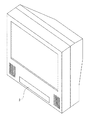
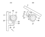
図1及び図2は開閉可能なドア板を備えた電子機器を示す斜視図であり、図1はドア板が閉鎖位置にある状態を示し、図2はドア板が開放位置にある状態を示す。図3は電子機器のフロントキャビネット単体の構造を示す斜視図である。図4から図7は本発明の第一実施例を示すもので、図4はドア板及び電子機器の凹み部近傍を一部切欠いて示す分解斜視図、図5はドア板が閉鎖位置及び開放位置にある状態の支柱近傍を示す側面図、図6は閉鎖位置にあるドア板と凹み部を示す平面側断面図、図7は開放位置にあるドア板及び凹み部の一部を示す部分拡大斜視図である。図8から図10は本発明の第二実施例を示すもので、図8はドア板及び電子機器の凹み部近傍を一部切欠いて示す分解斜視図、図9はドア板の取り付け部分近傍を示すフロントキャビネットの部分拡大斜視図、図10はドア板の開閉動作を示す側面側断面図である。 1 and 2 are perspective views showing an electronic device having a door plate that can be opened and closed. FIG. 1 shows a state in which the door plate is in a closed position, and FIG. 2 shows a state in which the door plate is in an open position. . FIG. 3 is a perspective view showing a structure of a single front cabinet of the electronic device. 4 to 7 show the first embodiment of the present invention. FIG. 4 is an exploded perspective view showing the door plate and the vicinity of the recessed portion of the electronic device. FIG. 6 is a side sectional view showing the door plate and the recessed portion in the closed position, and FIG. 7 is a partially enlarged view showing a part of the door plate and the recessed portion in the open position. It is a perspective view. FIGS. 8 to 10 show a second embodiment of the present invention. FIG. 8 is an exploded perspective view showing a part of the door plate and the vicinity of the recessed portion of the electronic device. FIG. 10 is a partially enlarged perspective view of the front cabinet shown, and FIG. 10 is a side sectional view showing the opening and closing operation of the door plate.
本発明の最良の実施形態として第一の実施例について図4から図7を基に説明する。図4は本発明による電子機器の凹み部1の開口部16を塞ぐドア板2の支持構造を示している。尚、図4の符号において従来技術の構造を示す図11と同一の符号に関する説明については、前述と同様の内容であることから、ここでの説明は割愛する。本実施例では、凹み部1の側壁11から突出して設けられた支柱40の円筒表面41において、その軸方向に延伸する溝45が形成されている。又、図5(A)に示すように、円筒表面41の溝45に対して所定の回動角度だけ離間した畝状リブ25が、ブラケット受容部材21、21のブラケット受容面22、22に形成されている。さらに、このブラケット受容部材21、21はドア板2との連結部に樋状の切欠き27を有し、分割延伸体29、29を一体に形成している。
As the best mode for carrying out the present invention, a first example will be described with reference to FIGS. FIG. 4 shows a support structure of the
尚、本実施例では図6に示すように、凹み部1の対向する側壁11及び14が奥壁15に向かってほぼ平行に配置されて相互に傾斜しておらず、ドア板2の横幅より若干大きくなる間隔だけ互いの側壁11及び14は離間している。そのため、極小の隙間がドア板2と凹み部1の側壁11及び14との間に存在する。
In the present embodiment, as shown in FIG. 6, the opposing
次に本実施例におけるドアの開放動作について説明する。電子機器の凹み部1を開こうとするとき、ユーザーは図5(A)において開口部を塞ぐ閉鎖位置にあるドア板2を開放位置に向けて、図の矢印方向に指などで回動させる。このとき、ドア板2は凹み部1の側壁11に設けられた支柱40をブラケット20が受容しているので、この支柱40を支点にドア板2が開放する方向へと枢動する。この間、ブラケット受容部材21、21のブラケット受容面22、22に形成した畝状リブ25は支柱40の円筒表面41と接触しながら、所定の回動角度だけ離間した溝45の位置まで移動し、その位置に達すると、ブラケット受容面22、22に形成した畝状リブ25が溝45に係合してドア板2の開放位置への回動が完了となる。畝状リブ25と円筒表面41との接触移動時、及び畝状リブ25と溝45との係合時においては、ブラケット受容部材21、21が樋状の切欠き27を持つ分割延伸体29、29の形状と材料の性質により、相互方向に応力を受けることによって撓み変形可能な状態としている。すなわち、ドア板2が開放位置と閉鎖位置との間で回動するとき、ブラケット受容部材21、21は分割延伸体29、29により拡離するように撓み変形し、相互方向への応力を受ける。図5(B)は溝45に畝状リブ25が係合してドア板2が開放位置に保持されている状態を示している。
Next, the door opening operation in this embodiment will be described. When opening the
電子機器の凹み部1をドア板2で塞ぐ場合には、ユーザーがドア板2のブラケット受容面22、22に形成した畝状リブ25を支柱40の円筒表面41に形成した溝45から溝のない円筒表面41へと乗り上げさせるために、図5(B)の矢印の方向へと指などで押して回動させる。このときも、樋状の切欠き27を持つ分割延伸体29、29の形状と材料の性質により、ブラケット受容部材21、21が撓み変形をして畝状リブ25の円筒表面41上への乗り上げを支援するので、ドア板2を容易に閉鎖位置まで移動することができる。尚、閉鎖位置にあるドア板2は図示されていないフック等によりその位置に保持されている。
When the recessed
次に図8から図9を参照して本発明の最良の実施形態として第二の実施例について説明する。図8は、本実施例におけるドア板2の支持構造を一部切欠いて示す分解斜視図である。図9は、本実施例におけるドア板2の取り付け部近傍を一部切欠いて示すフロントキャビネットの斜視図である。尚、第一の実施例と同様、従来技術と同じ部分については同一の符号を使用しており、従来技術と同一符号についての説明は割愛する。本実施例では、凹み部1の側壁11から突出して設けられた支柱40の突出先端部近傍より凹み部1の奥壁15に向けて延伸した支持部材47a、47bが設けられ、当該支持部材47a、47bを前記奥壁15と連結させることにより、前記支柱40が側壁11と奥壁15との両壁面で支持される構造となるので、支柱40の支持強度が向上すると共に、ドア板2を取り付ける際の補強となる。さらに、当該支柱40に嵌合するドア板2のブラケット20には、湾曲した2つのブラケット受容部材21、21のうち前記支持部材47aと当接する一方のブラケット受容部材21aの当接面側端部に軸方向へ突出した突起24が形成されている。
Next, a second example will be described as the best mode for carrying out the present invention with reference to FIGS. FIG. 8 is an exploded perspective view showing the support structure of the
続いて本実施例におけるドア板の開閉作動について、図10を参照して説明する。電子機器の凹み部1の前面に取り付けられたドア板2を開こうとするとき、ユーザーは図10(A)に示す開口部16を塞いでいるドア板2を開放位置に向けて図の矢印方向へと指などで回動させる。このとき、ドア板2は、凹み部1の側壁11に設けられた支柱40をブラケット20によって受容しているので、支柱40を支点としてドア板2が枢動する。図10(B)から図10(D)は、閉鎖位置にあるドア板2が開放位置の方向へと枢動している状態を連続的に示しており、ドア板2の矢印方向への枢動が進行して図10(E)に達すると、ブラケット受容部材21aの端部に形成した突起24が支持部材47aと当接する。ドア板2が開放位置に達するまではユーザーの指などによる矢印方向への回動が継続されるので、その応力により、ブラケット受容部材21aの端部に形成された突起24は支持部材47aとの当接面を擦れながら同方向への回動を継続する。
Next, the opening / closing operation of the door plate in the present embodiment will be described with reference to FIG. When opening the
ドア板2の回動をさらに続けると突起24が支持部材47aとの当接から解放され、当該突起24が支持部材47aと47bとの間に形成された間隙部で保持される。このときの状態が図10(F)であり、突起24が支持部材47a及び47bの間に形成された間隙部で保持される位置がドア板2の開放位置となる。したがって、開放位置にあるドア板2は、支持部材47aと突起24との係合により開放状態を保持することができる。
When the rotation of the
本発明の実施例1及び実施例2のドア板2では、開放位置と閉鎖位置との間における回動の途中状態において、凹み部1の側壁11、14にドア板2を接触させる必要がないために摩擦の発生及びそれによる不具合が生じることはない。又、開放位置での保持構造については、支柱40に形成した溝45にドア板2のブラケット受容部材21に形成した畝状リブ25を係合させる手段や、或いは支柱40の近傍に形成した支持部材47aにドア板2のブラケット受容部材21に形成した突起24を係合させる手段を用いることで、従来技術のような凹み部1の側壁11、14にドア板2を摩擦によって保持させる必要がなく、確実にドア板2を開放位置にて保持することが出来る。
In the
凹み部1の側壁11及び14が奥壁15に向かって平行に形成されているので、従来の側壁における傾斜状態にて生じていたドア板2或いは側壁11、14の外観を損なうような傷が生ずることなく、又、ドア板2と側壁11及び14とが接触しない構造としているため、従来のようにドア板2と側壁11及び14との接触具合が不充分なために開放位置においてドア板2を保持出来ないなどの不具合が生じることなく、ドア板2の開閉操作を行なうことができる。
Since the
又、ドア板2を上方に開く構造とすることで、ドア板2の開放位置における保持状態が長時間に亘ったとしても、空気中に浮遊する埃がドア板2に堆積することで凹み部1内部への塵埃の侵入を防止することが可能となる。
Further, by adopting a structure in which the
1 凹み部
2 ドア板
20 ブラケット
21 ブラケット受容部材
22 ブラケット受容面
24 突起
25 畝状リブ
27 切欠き
29 分割延伸体
40 支柱
45 溝
47 支持部材
DESCRIPTION OF
Claims (5)
The electronic device provided with the open / close door according to claim 3 or 4, wherein the door plate in the open position is held above the connection terminal and / or the operation unit.
Priority Applications (1)
| Application Number | Priority Date | Filing Date | Title |
|---|---|---|---|
| JP2005068734A JP2005290973A (en) | 2004-03-12 | 2005-03-11 | Electronic device equipped with opening/closing door |
Applications Claiming Priority (2)
| Application Number | Priority Date | Filing Date | Title |
|---|---|---|---|
| JP2004071785 | 2004-03-12 | ||
| JP2005068734A JP2005290973A (en) | 2004-03-12 | 2005-03-11 | Electronic device equipped with opening/closing door |
Publications (1)
| Publication Number | Publication Date |
|---|---|
| JP2005290973A true JP2005290973A (en) | 2005-10-20 |
Family
ID=35324212
Family Applications (1)
| Application Number | Title | Priority Date | Filing Date |
|---|---|---|---|
| JP2005068734A Withdrawn JP2005290973A (en) | 2004-03-12 | 2005-03-11 | Electronic device equipped with opening/closing door |
Country Status (1)
| Country | Link |
|---|---|
| JP (1) | JP2005290973A (en) |
Cited By (3)
| Publication number | Priority date | Publication date | Assignee | Title |
|---|---|---|---|---|
| JP2019221056A (en) * | 2018-06-19 | 2019-12-26 | 河村電器産業株式会社 | Distribution board housing |
| CN110620334A (en) * | 2018-06-19 | 2019-12-27 | 河村电器产业株式会社 | Distribution board case |
| CN110661175A (en) * | 2018-06-28 | 2020-01-07 | 河村电器产业株式会社 | Distribution board case |
-
2005
- 2005-03-11 JP JP2005068734A patent/JP2005290973A/en not_active Withdrawn
Cited By (8)
| Publication number | Priority date | Publication date | Assignee | Title |
|---|---|---|---|---|
| JP2019221056A (en) * | 2018-06-19 | 2019-12-26 | 河村電器産業株式会社 | Distribution board housing |
| CN110620334A (en) * | 2018-06-19 | 2019-12-27 | 河村电器产业株式会社 | Distribution board case |
| JP7049939B2 (en) | 2018-06-19 | 2022-04-07 | 河村電器産業株式会社 | Distribution board housing |
| CN110620334B (en) * | 2018-06-19 | 2023-05-23 | 河村电器产业株式会社 | Distribution board shell |
| CN110661175A (en) * | 2018-06-28 | 2020-01-07 | 河村电器产业株式会社 | Distribution board case |
| JP2020005421A (en) * | 2018-06-28 | 2020-01-09 | 河村電器産業株式会社 | Switchboard housing |
| JP7049947B2 (en) | 2018-06-28 | 2022-04-07 | 河村電器産業株式会社 | Distribution board housing |
| CN110661175B (en) * | 2018-06-28 | 2023-05-23 | 河村电器产业株式会社 | Distribution board shell |
Similar Documents
| Publication | Publication Date | Title |
|---|---|---|
| JP5154849B2 (en) | Drink container holding mechanism | |
| JP2008208684A (en) | Latch device and opening/closing device using it | |
| US20120039031A1 (en) | Electronic Apparatus | |
| TWI448626B (en) | Two-axles hinge of electronic apparatus | |
| JP2005290973A (en) | Electronic device equipped with opening/closing door | |
| CN101453841B (en) | Electronic device | |
| US7356826B2 (en) | Disk player casing with buffered lid | |
| WO2005013279A1 (en) | Disk drive device and installation mechanism for disk drive device | |
| JPH09282051A (en) | 180× rotation-type personal computer | |
| JPH08234672A (en) | Display device support mechanism | |
| US7360229B2 (en) | Optical disc cartridge and apparatus having a disc fixing/releasing mechanism for recording or reproducing data | |
| JP2008221873A (en) | Vehicle sunvisor | |
| CN201207282Y (en) | Slot-in type disk device | |
| JP2005198962A (en) | Lid stopper structure for rice cooker | |
| JP2009036965A (en) | Lid structure | |
| US20140084768A1 (en) | Electronic device, case unit, and locking device | |
| KR101566272B1 (en) | Docking hinge device | |
| JP3098379B2 (en) | Storage body | |
| JP2000322153A (en) | Portable information terminal | |
| US20130255155A1 (en) | Cover assembly and electronic device using the same | |
| JP2006298301A (en) | Movable storing pocket | |
| JP2006059892A (en) | Door structure of electronic apparatus | |
| JP2008106864A (en) | Folding type portable terminal | |
| JP2013109562A (en) | Pen case | |
| JP2006221267A (en) | Recording medium opening and closing mechanism |
Legal Events
| Date | Code | Title | Description |
|---|---|---|---|
| A300 | Withdrawal of application because of no request for examination |
Free format text: JAPANESE INTERMEDIATE CODE: A300 Effective date: 20080513 |