JP2005290888A - Press fitting support pile as well as execution and design methods thereof - Google Patents
Press fitting support pile as well as execution and design methods thereof Download PDFInfo
- Publication number
- JP2005290888A JP2005290888A JP2004108924A JP2004108924A JP2005290888A JP 2005290888 A JP2005290888 A JP 2005290888A JP 2004108924 A JP2004108924 A JP 2004108924A JP 2004108924 A JP2004108924 A JP 2004108924A JP 2005290888 A JP2005290888 A JP 2005290888A
- Authority
- JP
- Japan
- Prior art keywords
- press
- pile
- support pile
- fitting
- fit
- Prior art date
- Legal status (The legal status is an assumption and is not a legal conclusion. Google has not performed a legal analysis and makes no representation as to the accuracy of the status listed.)
- Granted
Links
- 238000000034 method Methods 0.000 title claims description 58
- 238000013461 design Methods 0.000 title claims description 36
- 230000003068 static effect Effects 0.000 claims abstract description 80
- 238000011156 evaluation Methods 0.000 claims abstract description 70
- 238000006073 displacement reaction Methods 0.000 claims abstract description 56
- 238000010276 construction Methods 0.000 claims description 27
- 239000000463 material Substances 0.000 claims description 4
- 239000002699 waste material Substances 0.000 abstract description 4
- 239000002689 soil Substances 0.000 description 16
- 230000015572 biosynthetic process Effects 0.000 description 9
- 238000005755 formation reaction Methods 0.000 description 9
- 238000012360 testing method Methods 0.000 description 8
- 238000010586 diagram Methods 0.000 description 7
- 230000000694 effects Effects 0.000 description 6
- 230000002093 peripheral effect Effects 0.000 description 5
- 238000005259 measurement Methods 0.000 description 3
- 230000035515 penetration Effects 0.000 description 3
- 230000007423 decrease Effects 0.000 description 2
- 230000003247 decreasing effect Effects 0.000 description 2
- 238000002347 injection Methods 0.000 description 2
- 239000007924 injection Substances 0.000 description 2
- 239000002245 particle Substances 0.000 description 2
- 229910000831 Steel Inorganic materials 0.000 description 1
- 239000000853 adhesive Substances 0.000 description 1
- 230000001070 adhesive effect Effects 0.000 description 1
- 238000006243 chemical reaction Methods 0.000 description 1
- 239000004927 clay Substances 0.000 description 1
- 239000002131 composite material Substances 0.000 description 1
- 238000011835 investigation Methods 0.000 description 1
- 230000007774 longterm Effects 0.000 description 1
- 238000011867 re-evaluation Methods 0.000 description 1
- 239000004576 sand Substances 0.000 description 1
- 238000004904 shortening Methods 0.000 description 1
- 239000007787 solid Substances 0.000 description 1
- 238000007619 statistical method Methods 0.000 description 1
- 239000010959 steel Substances 0.000 description 1
Images
Landscapes
- Foundations (AREA)
- Placing Or Removing Of Piles Or Sheet Piles, Or Accessories Thereof (AREA)
- Piles And Underground Anchors (AREA)
- Investigation Of Foundation Soil And Reinforcement Of Foundation Soil By Compacting Or Drainage (AREA)
Abstract
Description
本発明は、地盤に圧入されて建築物の基礎をなす圧入支持杭と、この圧入支持杭の施工方法及び設計方法に関する。 The present invention relates to a press-fit support pile that is press-fitted into the ground and forms the foundation of a building, and a construction method and a design method for the press-fit support pile.
従来より、建築物の基礎として地盤に杭を打ち込み、この上部に建築物を構築することで杭によって建築物を支持する支持杭が知られている。
この支持杭の設計、施工にあたっては、標準貫入試験によって地層の構成を調査するとともに、地層の硬さを評価する値であるN値を求め、ある一定の値以上のN値と厚さを持つ地層を支持層とするとしている。
Conventionally, a support pile that supports a building by a pile by driving a pile into the ground as the foundation of the building and constructing the building on top of this is known.
In designing and constructing this support pile, the structure of the formation is investigated by a standard penetration test, the N value that is a value for evaluating the hardness of the formation is obtained, and the N value and thickness are equal to or greater than a certain value. The stratum is assumed to be the support layer.
また、支持杭の先端部における最大の支持力である極限支持力は、テルツァギの理論を元にマイヤーホフが拡張した理論によって推定できるとされている。
この理論によれば、支持杭の先端部の地盤は理想状態において、あるモデルに従う挙動をすると考えられており、土質によって決まる土質の粘着力、内部摩擦角、上載圧力などの基礎常数をこのモデルに適用すれば、杭先端部での極限支持力を推定できるとされている(例えば、非特許文献1参照)。
また、実際に施工した支持杭の支持力の評価は、載荷試験によって行われており、これによって、杭の第1限界支持力、第2限界支持力を求め、支持杭の極限支持力を算出して評価している。
According to this theory, the ground at the tip of the support pile is considered to behave according to a certain model in an ideal state, and the basic constants such as the adhesive strength of the soil, the internal friction angle, and the upper pressure are determined by this model. If it applies to, it is supposed that the ultimate support force in a pile front-end | tip part can be estimated (for example, refer nonpatent literature 1).
In addition, the evaluation of the support capacity of the support pile actually constructed is carried out by a loading test. By this, the first limit support capacity and the second limit support capacity of the pile are obtained, and the ultimate support capacity of the support pile is calculated. And evaluate.
標準貫入試験によってN値を求める方法においては、測定条件などによって値が変動することがある。
また、テルツァギらの理論における理想状態のモデルで用いられる土質の基礎常数は、いずれも推定値であり、さらに、実際の杭先端部における地盤の挙動は、地盤内部の構造が複雑なため、必ずしもこの理想状態を取るとは言えない。すなわち、上述したように、テルツァギらの理論における極限支持力はあくまでも推定値である。
In the method of obtaining the N value by the standard penetration test, the value may vary depending on the measurement conditions.
In addition, the basic constants of the soil used in the ideal state model in Tertzagi's theory are all estimated values.Furthermore, the actual behavior of the ground at the tip of the pile is not necessarily because the internal structure of the ground is complex. It cannot be said that this ideal state is taken. In other words, as described above, the ultimate supporting force in the theory of Tertzagi et al. Is only an estimated value.
従来は、これらN値や理論を判断基準として支持杭を設計しているが、上述のように、これらは不確定な要素を含んでいる。
よって、支持杭の設計段階において安全率等を多く取るような設計とするため、深い所にある硬い地層を支持層として、極端に長い支持杭を設計することもあった。
しかし、支持杭の使用荷重等によっては、これより浅い層を支持層とすることが可能であり、実際の使用荷重に対する無駄が多くなっていた。
Conventionally, support piles are designed based on these N values and theories as criteria, but as described above, these include uncertain elements.
Therefore, an extremely long support pile may be designed using a hard stratum in a deep place as a support layer in order to make a design that takes a large safety factor in the design stage of the support pile.
However, depending on the use load of the support pile, etc., it is possible to use a shallower layer as a support layer, and waste for the actual use load has increased.
さらに、載荷試験によって支持杭の支持力を測定する場合には、支持杭の施工後に試験に必要な装置等を搬入して行うため、工期が長くなるとともにコストも増大する。また、載荷試験に用いた支持杭は破壊されてしまうため、使用される支持杭に対して試験を行うことはできなかった。 Furthermore, when measuring the support force of a support pile by a loading test, since it carries in and carrying out the apparatus etc. which are required for a test after construction of a support pile, a construction period becomes long and cost also increases. Moreover, since the support pile used for the loading test will be destroyed, it was not possible to test the support pile used.
本発明の課題は、地盤に圧入されて建築物を支持する圧入支持杭の設計、施工において、砂質土層等を地盤改良することで支持杭の使用荷重に見合った地層を支持層にできるようにし、施工のコストを削減することである。
また、実際に使用される圧入支持杭についての特性を、実測値から求められるようにし、支持杭の信頼性を高めるとともに、安全率を多く取ることで生じていた無駄を無くすことである。
The object of the present invention is to design and construct a press-fit support pile that is press-fitted into the ground to support the building. And to reduce the construction cost.
In addition, the characteristics of the press-fit support piles that are actually used are to be obtained from the actual measurement values, thereby improving the reliability of the support piles and eliminating the waste caused by taking a large safety factor.
以上の課題を解決するため、請求項1に記載の発明は、例えば、図1から4に示すように、地盤に圧入されて上部構造物を支持する圧入支持杭1の施工方法において、
前記圧入支持杭1にかかる摩擦抵抗を低減させるように前記圧入支持杭1を圧入する圧入工程と、
前記圧入工程における圧入力が所望の圧入力の範囲となった場合に、前記圧入工程で圧入された前記圧入支持杭1に対して、前記圧入力に対応する静荷重の付加と解放を前記圧入支持杭1の垂直変位量が所定の変位量以下となるまで繰り返す静荷重付加工程と、
を有することを特徴とする。
In order to solve the above problems, the invention according to
A press-fitting step of press-fitting the press-
When the pressure input in the press-fitting step is in a desired press-input range, the press-fitting is performed by adding and releasing a static load corresponding to the press-fitting to the press-
It is characterized by having.
ここで、「圧入支持杭」とは、圧入工法を用いて構築された支持杭のことである。
このように、圧入支持杭1にかかる摩擦抵抗を低減させながら圧入する圧入工程を有することで、圧入工程の後に行う静荷重付加工程で、付加した静荷重を効率よく圧入支持杭杭先端部に伝達できるようになる。また、摩擦抵抗による圧入支持杭1の支持力を排除でき、圧入支持杭先端部の地盤の支持力のみに基づく圧入支持杭1の特性を求められる。
また、圧入工程における圧入力が所望の圧入力の範囲となった場合に、圧入支持杭1に対して静荷重の付加と解放を繰り返す静荷重付加工程を有することで、圧入支持杭先端部の地盤をほぼ弾性化することができ、地盤を改良することができる。
さらに、この静荷重の付加と解放を圧入支持杭1の垂直変位量が所定の変位量以下となるまで繰り返すことで、静荷重の変化と圧入支持杭1の垂直変位量が比例関係となり(地盤が弾性化)、この関係から圧入支持杭1の特性を求めて評価することができる。
Here, the “press-fit support pile” is a support pile constructed using the press-fit method.
Thus, by having a press-fitting process of press-fitting while reducing the frictional resistance applied to the press-
In addition, when the pressure input in the press-fitting process is in the range of the desired press-fitting, it has a static load adding process that repeats the addition and release of the static load to the press-
Furthermore, by repeating the addition and release of this static load until the vertical displacement of the press-
請求項2に記載の発明は、請求項1に記載の圧入支持杭の施工方法であって、例えば、図1または2に示すように、前記圧入工程における圧入方法は、所定の長さ範囲の圧入を順次繰り返す方法とし、かつ、前記圧入方法は前記所定の長さ範囲で圧入された前記圧入支持杭1を、前記所定の長さ範囲で引き上げ、再び圧入する工程を含むことを特徴とする。
Invention of
このように、圧入支持杭1の圧入の際に、所定の長さ範囲で圧入された圧入支持杭1を、所定の長さ範囲で引き上げ、再び圧入するようにしたことで、圧入支持杭1の周面と地盤との間に働く摩擦抵抗が低減されるとともに、圧入支持杭1の周面付近の地盤内部における剪断破壊が促進され、圧入支持杭1に働く摩擦抵抗を低減できる。
In this way, when the press-
請求項3に記載の発明は、請求項1または2に記載の圧入支持杭の施工方法であって、例えば、図4または6に示すように、前記圧入支持杭の垂直変位量が所定の変位量以下となった状態における前記静荷重の変化と前記圧入支持杭の垂直変位量の関係から、前記圧入支持杭の特性を求めて評価することを特徴とする。
Invention of Claim 3 is the construction method of the press-fit support pile of
このように、静荷重の変化と圧入支持杭の垂直変位量の関係から圧入支持杭の特性を推定値ではなく確定値として求め、圧入支持杭としての評価をすることができ、過大な安全率を見込んで必要以上に深い地層まで支持杭を施工する必要がなくなる。
ここで圧入支持杭の特性とは、静荷重の変化と圧入支持杭の垂直変位量の関係から求められるバネ常数と、静荷重付加工程で加えた静荷重の最大値である弾性限界荷重と、圧入支持杭に弾性限界荷重が加わったときの変位である弾性限界変位のことである。
また、実際に施工した圧入支持杭の特性を、確定値として把握できるので、支持杭の信頼性が向上する。
In this way, the characteristics of a press-fit support pile can be obtained as a deterministic value rather than an estimated value from the relationship between the change in static load and the vertical displacement of the press-fit support pile, and it can be evaluated as a press-fit support pile. Therefore, it is no longer necessary to construct support piles deeper than necessary.
Here, the characteristics of the press-fit support pile are the spring constant obtained from the relationship between the change of the static load and the vertical displacement of the press-fit support pile, the elastic limit load that is the maximum value of the static load added in the static load addition process, It is the elastic limit displacement that is the displacement when the elastic limit load is applied to the press-fit support pile.
Moreover, since the characteristic of the press-fit support pile actually constructed can be grasped as a definite value, the reliability of the support pile is improved.
請求項4に記載の発明は、請求項3に記載の圧入支持杭の施工方法であって、例えば、図1から6に示すように、前記圧入支持杭1を圧入する前に、前記圧入支持杭1の前記特性を求めて評価する評価杭2を、前記圧入工程と前記静荷重付加工程とを用いて圧入して前記特性を求めて評価した後、前記特性の評価に基づき設計された前記圧入支持杭1の圧入を行うことを特徴とする。
Invention of Claim 4 is the construction method of the press-fit support pile of Claim 3, Comprising: For example, as shown in FIGS. 1-6, before press-fitting the press-
このように、評価杭2を用いて圧入支持杭1としての特性を求めて評価してから圧入支持杭1を施工することで、地盤の状態や上部構造物の設計に合わせた適切な圧入支持杭1を選択することができる。
すなわち、評価杭2で求められた特性としての弾性限界荷重、弾性限界変位及びバネ常数等と上部構造物の設計から、上部構造物を支持する支持杭としての性能を評価し、この評価に基づいて支持杭の設計変更をすることができる。
In this way, by applying the press-in
That is, the performance as a support pile that supports the upper structure is evaluated from the design of the upper structure and the elastic limit load, elastic limit displacement, spring constant, etc. as the characteristics obtained in the
請求項5に記載の発明は、地盤に圧入されて上部構造物を支持する圧入支持杭の設計方法において、例えば、図1から6に示すように、
前記圧入支持杭1の特性を求めて評価する評価杭2を、前記評価杭2にかかる摩擦抵抗を低減させるように圧入する圧入工程と、
前記評価杭2に対して所定の静荷重の付加と解放を、前記評価杭2の垂直変位量が所定の変位量以下となるまで繰り返す静荷重付加工程と、を用いて圧入し、
前記評価杭2の垂直変位量が所定の変位量以下となった状態における前記静荷重の変化と前記評価杭2の垂直変位量の関係から前記特性を求めて評価し、
前記特性の評価に基づき圧入支持杭1の数、材質、長さ、断面形状などの圧入支持杭1に関する設計データを決定することを特徴とする。
The invention according to claim 5 is a method for designing a press-fit support pile that is press-fitted into the ground and supports the upper structure. For example, as shown in FIGS.
A press-fitting step of press-fitting the
Press-fit using a static load addition step that repeats the addition and release of a predetermined static load to the
The vertical displacement amount of the
The design data regarding the press-
このように、評価杭2によって圧入支持杭1としての特性を求めて評価し、この特性に基づき圧入支持杭1に関する設計データを決定することで、請求項4の効果と同様の効果を得ることができる。
Thus, the effect as the effect of Claim 4 is acquired by calculating | requiring and evaluating the characteristic as the press-
請求項6に記載の発明は、請求項1から4の何れか一項に記載の圧入支持杭の施工方法を用いることで構築された圧入支持杭であって、例えば、図1から5に示すように、前記圧入工程を行った後に前記静荷重付加工程を行うことで構築されたことを特徴とする。
The invention according to claim 6 is a press-fit support pile constructed by using the press-fit support pile construction method according to any one of
このような圧入支持杭1によれば、請求項1から4の何れか一項の効果と同様の効果を得ることができる。
According to such a press-
請求項7に記載の発明は、請求項5に記載の圧入支持杭の設計方法で設計された圧入支持杭であって、例えば、図1から5に示すように、前記評価杭2の特性の評価に基づいて設計され、かつ、前記圧入工程を行った後に前記静荷重付加工程を行うことで構築されたことを特徴とする。 The invention according to claim 7 is a press-fit support pile designed by the press-fit support pile design method according to claim 5, for example, as shown in FIGS. It is designed based on the evaluation, and is constructed by performing the static load applying step after performing the press-fitting step.
このような圧入支持杭1によれば、請求項5の効果と同様の効果を得ることができるとともに、請求項1に記載の効果と同様の効果を得ることができる。
According to such a press-
本発明によれば、圧入支持杭に対して静荷重の付加と解放を繰り返すことで地盤をほぼ弾性化し、圧入支持杭の使用荷重に見合った地層を支持層とすることができる。また、圧入支持杭の特性を確定値として得ることができ、これをもとに圧入支持杭の設計、施工を行うことで、コストを削減できるとともに、圧入支持杭の信頼性を高めることができる。 According to the present invention, it is possible to make the ground substantially elastic by repeating the addition and release of a static load to the press-fit support pile, and to make the formation suitable for the load used by the press-fit support pile as a support layer. In addition, the characteristics of the press-fit support pile can be obtained as a deterministic value. By designing and constructing the press-fit support pile based on this, the cost can be reduced and the reliability of the press-fit support pile can be improved. .
以下、本発明を実施するための最良の形態を詳細に説明する。
本発明において、圧入支持杭1の施工を行う杭圧入引抜装置は、本体に対して上下に昇降可能な杭を把持する把持手段を備え、自重や反力装置、先に圧入した杭等から反力を得て地盤に杭を圧入できるものである。
以下、このような杭圧入引抜装置を用いた圧入支持杭1の設計方法及び施工方法について説明する。
Hereinafter, the best mode for carrying out the present invention will be described in detail.
In the present invention, the pile press-in / pull-out device for constructing the press-
Hereinafter, the design method and construction method of the press-
まず、圧入支持杭1を施工する地盤に対して、ボーリング調査などの土質調査を行い、地盤の状態を調査する。この土質調査の結果や、上部構造物の設計などから、支持層として好適な地層の見当をつけ、圧入支持杭1として適当なものを評価杭2として仮設計する。
なお、後述する静荷重付加工程における静荷重の付加と解放による地盤の弾性化は、荷重に対して地盤が変形するときに時間依存性がないもの、つまり、荷重の増減速度に関係なく荷重と変位がほぼ線形に対応するもの、例えば、砂質土、砂、礫質土及び礫のように土質中に粒径が0.075mm以上の粒子を50%より多く含むものに対して好適である。これ以外の土質において、例えば、シルトは支持層として不適である。また、粘性土は、荷重に対する地盤の変位が荷重の増減速度にも影響されるので、荷重と変位の関係が複雑となり、本発明の工法で弾性化しない可能性があるため不適である。
このため、本発明の工法において、圧入支持杭1を支持する支持層としては、例えば、砂質土のような、荷重に対して変形するときに時間依存性がない土質からなり、かつ、所定の厚みを有する層であることが必要であって、土質調査によってこのような層の存在を確認する必要がある。
First, a soil survey such as a boring survey is performed on the ground on which the press-fitting
In addition, the elasticity of the ground by adding and releasing the static load in the static load adding process described later has no time dependency when the ground is deformed with respect to the load, that is, the load is independent of the load increasing / decreasing speed. Suitable for those in which the displacement corresponds to almost linear, for example, sandy soil, sand, gravelly soil, and gravel containing more than 50% of particles having a particle size of 0.075 mm or more in the soil. . In soils other than this, for example, silt is not suitable as a support layer. In addition, the clay soil is not suitable because the displacement of the ground relative to the load is also affected by the load increasing / decreasing speed, and the relationship between the load and the displacement becomes complicated and may not be elasticized by the method of the present invention.
For this reason, in the construction method of the present invention, the support layer for supporting the press-
次に、評価杭2を地盤に圧入する圧入工程を行う。
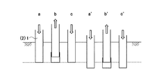
土質調査の結果から支持層として適用でき得ると判断された地層に対し、杭圧入引抜装置を用いて評価杭2に働く摩擦抵抗を低減させるようにして圧入する。この評価杭2に働く摩擦抵抗を低減させる圧入方法としては、例えば、図1に示すように、(a)所定の長さだけ評価杭2を圧入した後、(b)この所定の長さの範囲で評価杭2を引き上げ、(c)再び引き上げた長さだけ評価杭2を圧入する動作を一つの工程とし、この工程を繰り返して所定の深さまで評価杭2を圧入する方法とする。
Next, a press-fitting process for press-fitting the
The formation determined to be applicable as a support layer from the result of the soil investigation is press-fitted so as to reduce the frictional resistance acting on the
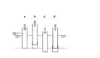
また、図2に示すように、(a)評価杭2を所定の長さ圧入し、(b)この所定の長さの範囲で評価杭2を引き上げる動作を一つの工程とし、圧入の際に、引き上げた長さ以上圧入するようにして順次これを繰り返すことで所定の深さまで評価杭2を圧入するようにしても良い。すなわち基本的に、圧入工程における圧入方法は、所定の長さ範囲の圧入を順次繰り返す方法とし、かつ、所定の長さ範囲で圧入された圧入支持杭1を、所定の長さ範囲で引き上げ、再び圧入する工程を含む方法とする。
このように評価杭2を上下動させながら圧入することで、評価杭2の周面と地盤の間に働く摩擦抵抗が低減されるとともに、評価杭2の周面付近の地盤内部における剪断破壊が促進され、評価杭2に働く摩擦抵抗が低減される。
よって、圧入支持杭1を圧入する時の力の損失を最低限にすることができ、軸力として圧入支持杭1の先端部に伝達できるようになる。
Moreover, as shown in FIG. 2, (a) the
Thus, by press-fitting while moving the
Therefore, the loss of force when press-fitting the press-
また、圧入支持杭1が上部構造物を支持する支持力は、圧入支持杭1の先端部の地盤による支持力と、圧入支持杭1に働く摩擦抵抗による支持力とに分けられる。このうち圧入支持杭1に働く摩擦抵抗は、圧入支持杭1の周面と地盤との摩擦抵抗だけでなく、圧入支持杭1周辺の地盤内部の状態にも影響され、振動などによって圧入支持杭1周辺の地盤の内部で剪断破壊が起こることで減少する。すなわち、摩擦抵抗による支持力は、施工からの時間の経過とともに減少するものである。施工された圧入支持杭1は、後から補修や交換が困難なため、長期的な圧入支持杭1の信頼性を評価するにあたっては、当初から摩擦抵抗による支持力を考慮せず、杭先端部の地盤による支持力のみから求められた特性に基づく評価をする必要がある。よって、圧入工程において、杭に働く摩擦抵抗を低減するように圧入することが望ましい。
Further, the supporting force with which the press-
上述のように摩擦抵抗を低減させながら評価杭2の圧入を行い、土質調査により支持層として適用でき得ると判断された地層のうち、評価杭2を圧入するときの圧入力が所望の圧入力の範囲である地層、すなわち、圧入力が、設計段階における圧入支持杭1の使用荷重の限界値以上必要である地層に達したら静荷重付加工程を行う。この静荷重付加工程によって、杭先端部の地盤をほぼ弾性化するとともに、評価杭2の特性の評価を行うことができる。ここで、圧入力とは、圧入時に杭先端部にかかる圧力のことである。
As described above, the
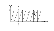
図3には、この静荷重付加工程における時間に対する静荷重の変化を示した。この静荷重付加工程は、静荷重を掛けない状態Aから、所定の静荷重を付加した状態Bを経て、再び静荷重を解放して静荷重を掛けない状態Cとなるまでを1サイクルとし、これを後述するように地盤が弾性化するまで繰り返す。
なお、このとき加える静荷重の最大値Pは、圧入工程でこの地層に評価杭2を圧入したときの圧入力(圧入最終荷重)に対応するものとする。すなわち、圧入最終荷重と等しいか、圧入支持杭1の使用荷重の限界値を下回らない範囲で圧入最終荷重よりも小さいものとする。また、Bの状態においては、付加した静荷重の最大値Pで静荷重を保持せず、すぐに解放するものとする。さらに、静荷重を解放した状態A、Cにおいては、静荷重を完全に0とする必要はなく、若干の静荷重が残っていても良い。
In FIG. 3, the change of the static load with respect to time in this static load addition process was shown. This static load adding step is one cycle from the state A in which no static load is applied to the state C in which the static load is released again after passing through the state B to which a predetermined static load is applied, This is repeated until the ground becomes elastic as will be described later.
In addition, the maximum value P of the static load applied at this time shall correspond to the press input (press-fit final load) when the
ここで、この静荷重付加工程における地盤の弾性化の過程について説明する。
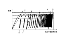
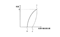
地盤に対して評価杭2を通じて静荷重を付加すると地盤が沈み、この静荷重を解放すると沈んでいた地盤が元に戻る。この地盤の変位は杭頭の垂直変位量により観測でき、この杭頭の垂直変位量と荷重の変化との関係を示したものが図4であり、このうち、静荷重付加工程の1サイクルにおける杭頭の垂直変位量と荷重の変化を示したものが図5である。
Here, the process of elasticizing the ground in the static load applying step will be described.
When a static load is applied to the ground through the
図5において、静荷重を付加する前のH点(図4のD点の状態に対応)の状態から静荷重を付加していくと、静荷重の増加に伴い杭頭が変位して実線で示した経路を辿りI点(図4のE点の状態に対応)の状態となる。このI点の状態から静荷重を解放すると、沈んでいた地盤が戻るため、点線で示した経路を辿りJ点(図4のF点の状態に対応)の状態となる。静荷重付加工程の初期の状態においては、地盤の沈み量よりも地盤の戻り量が少ないため、H点とJ点は一致しない。つまり、J点の状態においては、H点の状態よりも杭頭が沈んでいることとなる。 In FIG. 5, when a static load is applied from the state of point H before applying the static load (corresponding to the state of point D in FIG. 4), the pile head is displaced as the static load increases, and the solid line The route shown is followed to a state of point I (corresponding to the state of point E in FIG. 4). When the static load is released from the state of point I, the ground that has sunk returns, so that the path indicated by the dotted line is followed to a state of point J (corresponding to the state of point F in FIG. 4). In the initial state of the static load application step, the ground return amount is smaller than the ground sinking amount, so the H point and the J point do not match. That is, in the state of point J, the pile head is sinking more than in the state of point H.
引き続き静荷重の付加と解放を繰り返すと、図4に示すように、杭頭が当初の位置より沈んだ位置となるが、静荷重の付加前における杭頭の垂直変位量(図5のH点)と、静荷重の解放後における杭頭の垂直変位量(図5のJ点)の差が収束してほぼ0となる(図4のGの状態)。このように、静荷重の付加前と静荷重の解放後での杭頭の垂直変位量の差がほぼ一致し、静荷重の変化と杭頭の垂直変位量が比例関係となり、線形的な挙動を示すようになった状態を地盤が弾性化したと呼ぶ。
なお、弾性化した地盤において、静荷重の付加と杭頭の垂直変位量の関係は、完全な線形ではなく、静荷重の増加時と減少時とで同じ荷重がかかっていても異なった変位量を示すが、静荷重の付加前と静荷重の解放後での杭頭の垂直変位量の差がほぼなくなった状態を地盤が弾性化した状態とする。
If the addition and release of the static load are repeated continuously, the pile head will be in a position where it sinks from the initial position as shown in FIG. 4, but the vertical displacement amount of the pile head before application of the static load (point H in FIG. 5) ) And the vertical displacement (point J in FIG. 5) of the pile head after the static load is released converges to become almost 0 (state G in FIG. 4). In this way, the difference in the vertical displacement of the pile head before and after the release of the static load is almost the same, and the change in the static load and the vertical displacement of the pile head are in a proportional relationship. This state is called elastic ground.
In the elasticized ground, the relationship between the addition of static load and the vertical displacement of the pile head is not perfectly linear, and the amount of displacement differs even when the same load is applied when the static load increases and decreases. However, the state in which the difference between the vertical displacements of the pile head before the application of the static load and after the release of the static load is almost eliminated is defined as a state in which the ground is elasticized.
そして、図4に示すような杭頭の垂直変位と荷重の変化との関係を示した図において、静荷重の付加前の状態D(図5のH点)と付加後の状態E(図5のI点)を結んだ直線のうち、Gの状態における直線Lの傾きが、この評価杭2の特性であるバネ常数Kpとなる。
なお、この評価杭2のバネ常数Kpは、評価杭2先端の地盤のバネ常数と評価杭2自体のバネ常数が複合したものである。
And in the figure which showed the relationship between the vertical displacement of a pile head as shown in FIG. 4, and the change of a load, the state D (H point of FIG. 5) before addition of a static load and the state E (FIG. 5) after addition. Among the straight lines connecting the I points), the slope of the straight line L in the G state is the spring constant Kp, which is a characteristic of the
The spring constant Kp of the
次に、評価杭2の施工結果に基づく圧入支持杭1としての性能の評価について説明する。
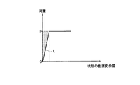
上述した評価杭2の施工によって求められた評価杭2のバネ常数Kpと、付加した静荷重の最大値から図6に示すような特性図を作成することができる。この特性図においては、縦軸が荷重、横軸が杭頭の垂直変位量となっており、原点Oを通り、静荷重付加工程で測定された評価杭2のバネ常数Kpを傾きとする直線Lが、付加した静荷重の最大値Pとなる点まで引かれている。
Next, the performance evaluation as the press-
A characteristic diagram as shown in FIG. 6 can be created from the spring constant Kp of the
静荷重付加工程において付加した荷重の最大値Pは、評価杭2を圧入する圧入工程において加えた圧入力とほぼ等しいか若干小さいものであり、このときの荷重より大きい荷重が杭に加わると、杭が地盤に圧入され、弾性挙動を示さなくなる。つまり、静荷重付加工程において付加した荷重の最大値Pが、この評価杭2の弾性限界荷重となり、この弾性限界荷重における杭頭の垂直変位量が、この評価杭2の弾性変位限界となる。よって、この評価杭2と同じ設計の圧入支持杭1の使用範囲は、弾性限界荷重以下で、かつ、バネ常数Kpを傾きとする直線よりも杭頭の垂直変位量が小さい範囲(網掛けの部分)となる。
The maximum value P of the load applied in the static load adding process is substantially equal to or slightly smaller than the press input applied in the press-fitting process for press-fitting the
特性図から求められた評価杭2の特性である弾性限界荷重、弾性変位限界、バネ常数Kpと上部構造物の設計から評価杭2の圧入支持杭1としての評価をし、この評価に基づいて、実際に施工する圧入支持杭1の数、材質、長さ、断面形状などを設計する。
例えば、仮設計した評価杭2の圧入工程において、使用荷重の限界値以上の圧入力を要する地層がなかったときは、杭の数を増やして各圧入支持杭1の使用荷重を減らすようにする。もしくは、圧入支持杭1の長さを長くし、より深いところにある強固な地盤を支持層としたりして十分な支持力を得られるようにする。ただし、圧入支持杭1の材質、断面形状なども総合的に判断し、細くて極端に長い杭を施工するような設計にならないようにする。逆に、仮設計よりも浅い位置に支持層として好適な地層があったときは、圧入支持杭1を短くすることや、数を減らすことでコストを削減できる。
The
For example, in the press-fitting process of the temporarily designed
また、特性図から明らかとなった圧入支持杭1の使用範囲(図6の網掛けの部分)に、当初の設計における支持杭の使用範囲が収まらないときも、適宜設計を変更して特性図に示された使用範囲に収まるようにする。
以上のような圧入支持杭1の設計において、当初の設計から大きな設計変更が必要となった場合は、新たな設計を元に再度評価杭2を仮設計して施工し特性を求め、特性の再評価を行っても良い。
In addition, when the range of use of the support pile in the initial design does not fit within the range of use of the press-fit support pile 1 (shaded portion in FIG. 6) that has been clarified from the characteristic diagram, the design can be changed as appropriate to change the characteristic diagram. To be within the range of use indicated in.
In the design of the press-
また、評価杭2の仮設計の段階において、従来のように標準貫入試験から得られるN値を元に仮設計しても良いが、本発明の施工方法によって構築された圧入支持杭1のデータが多数あれば、これを元に仮設計しても良い。
例えば、施工した土質と圧入支持杭1の形状などとともにその圧入支持杭1の特性図をデータベースとして蓄積しておき、新たに施工する場所における地盤の土質調査の結果をこのデータベースに照らし合わせ、圧入支持杭1として最適なものを選択できるようにする。このようにすれば、仮設計が容易になるとともに、仮設計と実際の設計との差を小さくでき、設計変更にかかる手間を削減できる。
Moreover, in the temporary design stage of the
For example, the construction of soil and the shape of the press-
このように、当初の設計に基づいて評価杭2を仮設計し、静荷重付加工程における静荷重の変化と垂直変位量の関係から特性を求めて評価することで、圧入支持杭1として適切なものを選択でき、施工の無駄を無くすことができる。また、上述の特性図の値はすべて実測値から求められた確定値であるので、この特性図を元に圧入支持杭1の設計を行えば、信頼性の高い圧入支持杭1を施工できるとともに、過大な安全率を見込む必要がなくなる。
In this way, the
圧入支持杭1の設計が決定したら圧入支持杭1の施工を行う。
圧入支持杭1の施工方法は、上述した評価杭2の施工方法と同じであり、圧入支持杭1にかかる摩擦抵抗を低減するように地盤に圧入する圧入工程と、目的とする地層において、圧入支持杭1の垂直変位が所定の変位量以下となるまで繰り返す静荷重の付加と解放を繰り返す静荷重付加工程により施工する。
以上のように設計、施工された圧入支持杭1は、この上部に構築される構造物を支持するものとして使用される。
When the design of the press-
The construction method of the press-
The press-
なお、この施工と同時にそれぞれの圧入支持杭1についての特性を求め、評価杭2と同じように評価することができる。これによって、現場で圧入支持杭1としての特性を確認しながら施工することができ、例えば、地盤中に不陸があっても確実に支持層を捕らえることができるとともに、この不陸を調査するための地盤調査をしなくてもすむのでコストを削減できる。また、全圧入支持杭1の特性から支持力分布のデータベースを作成可能であり、これらのデータを用いて統計的な手法により基礎の性能の解析が可能となる。
In addition, the characteristic about each press-
なお、以上の実施の形態においては、杭を上下動させながら圧入することで杭に働く摩擦抵抗を低減させるとしたが、本発明はこれに限定されるものではなく、例えば、鋼管杭のように断面形状が円形の杭においては、杭を回転させながら圧入することで杭に働く摩擦抵抗を低減するようにしても良い。
また、静荷重付加工程における静荷重の昇降圧速度も任意であり、その他、具体的な工程等についても適宜に変更可能であることは勿論である。
In the above embodiment, the frictional resistance acting on the pile is reduced by press-fitting while moving the pile up and down, but the present invention is not limited to this, for example, a steel pipe pile In addition, in a pile having a circular cross-sectional shape, the frictional resistance acting on the pile may be reduced by press-fitting while rotating the pile.
In addition, the step-up / step-down speed of the static load in the static load adding step is arbitrary, and it is needless to say that other specific steps can be appropriately changed.
1 圧入支持杭
2 評価杭
P 圧入最終荷重(弾性限界荷重)
1 Press-in
Claims (7)
前記圧入支持杭にかかる摩擦抵抗を低減させるように前記圧入支持杭を圧入する圧入工程と、
前記圧入工程における圧入力が所望の圧入力の範囲となった場合に、前記圧入工程で圧入された前記圧入支持杭に対して、前記圧入力に対応する静荷重の付加と解放を前記圧入支持杭の垂直変位量が所定の変位量以下となるまで繰り返す静荷重付加工程と、
を有することを特徴とする圧入支持杭の施工方法。 In the construction method of the press-fit support pile that is press-fitted into the ground and supports the superstructure,
A press-fitting step of press-fitting the press-fit support pile so as to reduce the frictional resistance applied to the press-fit support pile;
When the pressure input in the press-fitting process falls within a desired press-input range, the press-fitting support is used to add and release the static load corresponding to the press-fitting to the press-fitting support pile press-fitted in the press-fitting process. A static load application process that is repeated until the vertical displacement of the pile is equal to or less than a predetermined displacement,
A method for constructing a press-fit support pile characterized by comprising:
前記圧入支持杭の特性を求めて評価する評価杭を、前記評価杭にかかる摩擦抵抗を低減させるように圧入する圧入工程と、
前記評価杭に対して所定の静荷重の付加と解放を、前記評価杭の垂直変位量が所定の変位量以下となるまで繰り返す静荷重付加工程と、を用いて圧入し、
前記評価杭の垂直変位量が所定の変位量以下となった状態における前記静荷重の変化と前記評価杭の垂直変位量の関係から前記特性を求めて評価し、
前記特性の評価に基づき支持杭の数、材質、長さ、断面形状などの支持杭に関する設計データを決定することを特徴とする圧入支持杭の設計方法。 In the design method of the press-fit support pile that is press-fitted into the ground and supports the superstructure,
A press-fitting step of press-fitting an evaluation pile to be evaluated for characteristics of the press-fitting support pile so as to reduce frictional resistance applied to the evaluation pile;
Addition and release of a predetermined static load to the evaluation pile, and press-fitting using a static load addition step that repeats until the vertical displacement amount of the evaluation pile is equal to or less than a predetermined displacement amount,
From the relationship between the change in static load and the vertical displacement amount of the evaluation pile in a state where the vertical displacement amount of the evaluation pile is equal to or less than a predetermined displacement amount, the characteristics are evaluated and evaluated,
A design method for a press-fit support pile, wherein design data on the support pile such as the number, material, length, and cross-sectional shape of the support pile is determined based on the evaluation of the characteristics.
前記圧入工程を行った後に前記静荷重付加工程を行うことで構築されたことを特徴とする圧入支持杭。 A press-fit support pile constructed by using the construction method of the press-fit support pile according to any one of claims 1 to 4,
A press-fit support pile constructed by performing the static load applying step after performing the press-fit step.
前記評価杭の特性の評価に基づいて設計され、かつ、前記圧入工程を行った後に前記静荷重付加工程を行うことで構築されたことを特徴とする圧入支持杭。 A press-fit support pile designed by the press-fit support pile design method according to claim 5,
A press-fit support pile designed based on evaluation of the characteristics of the evaluation pile and constructed by performing the static load application step after performing the press-fit step.
Priority Applications (1)
| Application Number | Priority Date | Filing Date | Title |
|---|---|---|---|
| JP2004108924A JP4319935B2 (en) | 2004-04-01 | 2004-04-01 | Press-fit support pile and construction method and design method of press-fit support pile |
Applications Claiming Priority (1)
| Application Number | Priority Date | Filing Date | Title |
|---|---|---|---|
| JP2004108924A JP4319935B2 (en) | 2004-04-01 | 2004-04-01 | Press-fit support pile and construction method and design method of press-fit support pile |
Publications (2)
| Publication Number | Publication Date |
|---|---|
| JP2005290888A true JP2005290888A (en) | 2005-10-20 |
| JP4319935B2 JP4319935B2 (en) | 2009-08-26 |
Family
ID=35324130
Family Applications (1)
| Application Number | Title | Priority Date | Filing Date |
|---|---|---|---|
| JP2004108924A Expired - Fee Related JP4319935B2 (en) | 2004-04-01 | 2004-04-01 | Press-fit support pile and construction method and design method of press-fit support pile |
Country Status (1)
| Country | Link |
|---|---|
| JP (1) | JP4319935B2 (en) |
Cited By (4)
| Publication number | Priority date | Publication date | Assignee | Title |
|---|---|---|---|---|
| JP2010189901A (en) * | 2009-02-17 | 2010-09-02 | Nippon Steel Corp | Method for verifying bearing capacity of existing pile |
| CN101858082A (en) * | 2010-06-12 | 2010-10-13 | 上海智平基础工程有限公司 | Soft soil foundation new construction post pile pressing technology and construction method thereof |
| JP2018071320A (en) * | 2016-11-04 | 2018-05-10 | ジャパンパイル株式会社 | Ground excavation method |
| CN113742961A (en) * | 2021-08-16 | 2021-12-03 | 海天建设集团有限公司 | Construction process for taking engineering pile as support pile |
-
2004
- 2004-04-01 JP JP2004108924A patent/JP4319935B2/en not_active Expired - Fee Related
Cited By (5)
| Publication number | Priority date | Publication date | Assignee | Title |
|---|---|---|---|---|
| JP2010189901A (en) * | 2009-02-17 | 2010-09-02 | Nippon Steel Corp | Method for verifying bearing capacity of existing pile |
| CN101858082A (en) * | 2010-06-12 | 2010-10-13 | 上海智平基础工程有限公司 | Soft soil foundation new construction post pile pressing technology and construction method thereof |
| JP2018071320A (en) * | 2016-11-04 | 2018-05-10 | ジャパンパイル株式会社 | Ground excavation method |
| CN113742961A (en) * | 2021-08-16 | 2021-12-03 | 海天建设集团有限公司 | Construction process for taking engineering pile as support pile |
| CN113742961B (en) * | 2021-08-16 | 2023-11-17 | 海天建设集团有限公司 | Construction process for taking engineering pile as supporting pile |
Also Published As
| Publication number | Publication date |
|---|---|
| JP4319935B2 (en) | 2009-08-26 |
Similar Documents
| Publication | Publication Date | Title |
|---|---|---|
| Lee et al. | Equivalent pile load–head settlement curve using a bi-directional pile load test | |
| Fahmy et al. | Axial performance of helical tapered piles in sand | |
| Flynn et al. | Shaft resistance of driven cast-in-situ piles in sand | |
| Gabrielaitis et al. | Estimation of settlements of bored piles foundation | |
| Fellenius et al. | Response to load for four different bored piles | |
| Fellenius | Bearing capacity of footings and piles—A delusion | |
| Vukotić et al. | The influence of bond stress distribution on ground anchor fixed length design. Field trial results and proposal for design methodology | |
| Amornfa et al. | 3D numerical analysis of piled raft foundation for Ho Chi Minh City subsoil conditions | |
| JP4319935B2 (en) | Press-fit support pile and construction method and design method of press-fit support pile | |
| Sprince et al. | Helical pile behaviour and load transfer mechanism in different soils | |
| Zhang et al. | Field and theoretical analysis on the response of destructive pile subjected to tension load | |
| Grabe et al. | On the set-up of piles | |
| Dourado et al. | Field investigation of steel screw micropiles under axial loads in cohesionless and cohesive soils | |
| Kumara et al. | Effects of pile geometry on bearing capacity of open-ended piles driven into sands | |
| Naveen et al. | Numerical modeling of pile load test | |
| Yang et al. | APPLICATION OF POST-GROUTING IN BRIDGE FOUNDATION REINFORCEMENT: A CASE STUDY. | |
| Wang et al. | Field tests and simplified calculation method for static drill rooted nodular pile | |
| Crapps et al. | Compression top load reaching shaft bottom—theory vs. tests | |
| Gavin et al. | Axial resistance of CFA piles in Dublin Boulder Clay | |
| Hsu et al. | Evaluation of base grouting for the bearing behavior of barrette piles socketed in a gravel formation | |
| Fellenius | Capacity versus Deformation Analysis for Design of Footings and Pile Foundations | |
| Bagui et al. | Estimation of base grout quantity for cast in situ piles based on field test results | |
| Li | Axial and lateral behavior of helical piles under static loads | |
| Araújo et al. | Numerical study of geometric characteristics of helical piles subjected to uplift | |
| Üçdemir et al. | Effect of wall stiffness on excavation-induced horizontal deformations in stiff-hard clays |
Legal Events
| Date | Code | Title | Description |
|---|---|---|---|
| A621 | Written request for application examination |
Effective date: 20070330 Free format text: JAPANESE INTERMEDIATE CODE: A621 |
|
| A977 | Report on retrieval |
Effective date: 20081201 Free format text: JAPANESE INTERMEDIATE CODE: A971007 |
|
| A131 | Notification of reasons for refusal |
Free format text: JAPANESE INTERMEDIATE CODE: A131 Effective date: 20090303 |
|
| A521 | Written amendment |
Effective date: 20090428 Free format text: JAPANESE INTERMEDIATE CODE: A523 |
|
| TRDD | Decision of grant or rejection written | ||
| A01 | Written decision to grant a patent or to grant a registration (utility model) |
Free format text: JAPANESE INTERMEDIATE CODE: A01 Effective date: 20090526 |
|
| A01 | Written decision to grant a patent or to grant a registration (utility model) |
Free format text: JAPANESE INTERMEDIATE CODE: A01 |
|
| A61 | First payment of annual fees (during grant procedure) |
Free format text: JAPANESE INTERMEDIATE CODE: A61 Effective date: 20090529 |
|
| FPAY | Renewal fee payment (prs date is renewal date of database) |
Free format text: PAYMENT UNTIL: 20120605 Year of fee payment: 3 |
|
| R150 | Certificate of patent (=grant) or registration of utility model |
Free format text: JAPANESE INTERMEDIATE CODE: R150 |
|
| LAPS | Cancellation because of no payment of annual fees |