JP2005290864A - Floor panel supporting member and double-floor structure - Google Patents
Floor panel supporting member and double-floor structure Download PDFInfo
- Publication number
- JP2005290864A JP2005290864A JP2004108006A JP2004108006A JP2005290864A JP 2005290864 A JP2005290864 A JP 2005290864A JP 2004108006 A JP2004108006 A JP 2004108006A JP 2004108006 A JP2004108006 A JP 2004108006A JP 2005290864 A JP2005290864 A JP 2005290864A
- Authority
- JP
- Japan
- Prior art keywords
- floor panel
- floor
- panel support
- support member
- adjacent
- Prior art date
- Legal status (The legal status is an assumption and is not a legal conclusion. Google has not performed a legal analysis and makes no representation as to the accuracy of the status listed.)
- Pending
Links
Images


Landscapes
- Floor Finish (AREA)
Abstract
Description
本発明は、床パネル支持部材および二重床構造に関し、特に、床下空間からの空調空気の漏出量を抑えることができるとともに、床下空間における配線作業の容易化を図ることができる床パネル支持部材および二重床構造に関する。 The present invention relates to a floor panel support member and a double floor structure, and more particularly to a floor panel support member capable of suppressing the leakage of conditioned air from the underfloor space and facilitating wiring work in the underfloor space. And related to double floor structure.
従来、オフィス等には、基礎床から所定空間(床下空間)を隔てて床面を構成した二重床構造が採用されている。この二重床構造に設けられた床下空間は、電気系配線類を配置する空間や、空調空気を流通させる給気チャンバーとして利用されている。このような二重床構造は、基礎床面上に複数の床パネル支持部材を床パネルの一辺に相当する間隔で配置した後、隣接する床パネル支持部材間に、上面にパッキン等のシール材が取り付けられたストリンガーを掛け渡してストリンガーを升目状に形成し、この升目に合わせて床パネルを取り付けることにより構成されている。このような構成により、床下空間に空調空気を流通させて、床パネルに設けた吹出口から空調空気を吹き出させることができるとともに、床パネルの間から空調空気が漏出するのを防止できる。また、上記床下空間を利用して、電気系配線類を設置することができる(例えば、特許文献1参照)。
しかしながら、このような二重床構造では、升目部分から床パネルを取り外してから床下空間内の配線作業を行う際に、ストリンガーが配線の取り回しを阻害するため、配線作業が煩雑になるという問題がある。また、床パネルを取り外した後に、ストリンガーも取り外して作業することもできるが、この場合には、ストリンガーの取り外し作業が増え作業が煩雑になる。 However, in such a double floor structure, when the wiring work in the underfloor space is performed after the floor panel is removed from the mesh portion, the stringer obstructs the wiring operation, and thus the wiring work becomes complicated. is there. In addition, after the floor panel is removed, the stringer can also be removed for work, but in this case, the stringer removal work increases and the work becomes complicated.
本発明の目的は、床下空間からの空調空気の漏出量を抑えることができるとともに、床下空間における配線作業の容易化を図ることができる床パネル支持部材および二重床構造を提供することにある。 An object of the present invention is to provide a floor panel support member and a double floor structure capable of suppressing the leakage amount of conditioned air from the underfloor space and facilitating the wiring work in the underfloor space. .
本発明は、隣接配置される複数の床パネルを基礎床から上方へ離間した状態に支持することにより、前記床パネルと前記基礎床との間に空調空気を流通させる床下空間を備える二重床構造を構成するための床パネル支持部材であって、前記基礎床上に立設される支持脚と、前記支持脚の上部に設けられ、隣接配置される4枚の前記床パネルの各隅角部を支持する床パネル支持板と、この床パネル支持板から前記1枚の床パネルの隣接辺に沿って延びる4本の腕部と、前記各腕部の上面に配置され、隣接する2枚の前記床パネルに跨って当接する腕部シール材とを備えることを特徴とする。 The present invention provides a double floor having an underfloor space for circulating conditioned air between the floor panel and the foundation floor by supporting a plurality of adjacently arranged floor panels in a state of being spaced upward from the foundation floor. A floor panel support member for constituting a structure, the support leg standing on the foundation floor, and each corner of each of the four floor panels provided on the support leg and arranged adjacent to each other A floor panel support plate that supports the four arm portions that extend from the floor panel support plate along the adjacent side of the one floor panel, and two adjacent sheets disposed on the upper surface of each arm portion. It is provided with the arm part seal material which straddles across the floor panel.
本発明によれば、従来のようなストリンガーで隣接する床パネル支持部材間を接続していないので、隣接する床パネル下の床下空間を跨ぐようにOA機器類等の配線作業を行う場合であっても、簡単に作業を実施でき、居室空間内のレイアウト変更も容易となる。また、このようにストリンガーを用いないため、部材点数を減らすことができ、床パネル支持部材が安価となる。また、各腕部を所定の長さ寸法で形成することにより、床下空間から漏出する空調空気の量を抑えることができる。 According to the present invention, since the adjacent floor panel support members are not connected by a stringer as in the prior art, the wiring work of OA equipment or the like is performed so as to straddle the underfloor space under the adjacent floor panel. However, the work can be easily performed, and the layout in the living room can be easily changed. Moreover, since a stringer is not used in this way, the number of members can be reduced, and the floor panel support member becomes inexpensive. Moreover, the amount of conditioned air leaking from the underfloor space can be suppressed by forming each arm portion with a predetermined length.
ここで、前記各腕部は、隣接する2枚の前記床パネル間の隙間を介して前記床下空間から居室空間へ漏出する空調空気量が、4.0〜15.0m3/h・m2となる長さ寸法で形成されていることとすることができる。
ここで、居室空間内の標準的な空調循環空気量は、例えば16〜50m3/h・m2程度であるから、4.0〜15.0m3/h・m2の漏出する空調空気量は標準的な空調循環空気量の25〜30%に相当することになる。ここで、前記床パネルとしては、正方形ではなくて長方形としてもよい。また、前記居室空間には、一般住宅の居室やオフィス等の室内が包まれる。
Here, each arm portion has an air-conditioning air amount that leaks from the underfloor space to the living room space through a gap between the two adjacent floor panels in a range of 4.0 to 15.0 m 3 / h · m 2. It can be formed with the length dimension which becomes.
Here, a standard air-conditioning circulating air of the room space, for example because it is 16~50m 3 / h · m 2 about, conditioned air amount leaking 4.0~15.0m 3 / h · m 2 Corresponds to 25-30% of the standard air-conditioning circulating air volume. Here, the floor panel may be rectangular instead of square. The living room space includes a room of a general house or an office.
また、以上の床パネル支持部材において、前記床パネルの縦横の二辺の長さ寸法の合計値から、前記床パネル支持板の略中心位置から前記腕部の先端までの長さ寸法である持出寸法を4倍した値を減じた値が、0.2m以下であることが好ましい。
また、以上の床パネル支持部材において、前記腕部シール材は、隣接する2枚の前記床パネルの隣接する辺ごとにそれぞれが当接する2つの当接部を備える構成としてもよい。この場合には、床パネルの製造精度や施工精度が劣って誤差が生じる場合であっても、各床パネルに対応する当接部をそれぞれ設けたので、前記誤差を吸収でき漏気防止効果を高めることができる。
Further, in the above floor panel support member, the holding panel has a length dimension from the total value of the length dimensions of the two sides of the floor panel to the approximate center position of the floor panel support plate to the tip of the arm portion. The value obtained by subtracting the value obtained by multiplying the projected dimension by 4 is preferably 0.2 m or less.
Moreover, the above floor panel support member WHEREIN: The said arm part sealing material is good also as a structure provided with two contact parts which each contact | abuts for every adjacent edge | side of the two adjacent floor panels. In this case, even if the manufacturing accuracy or construction accuracy of the floor panel is inferior and an error occurs, the contact portion corresponding to each floor panel is provided, so that the error can be absorbed and the leakage prevention effect can be obtained. Can be increased.
以上の床パネル支持部材において、前記各腕部は、前記床パネル支持板の略中心位置から四方へと延びるように形成されている構成を採用できる。
また、前記床パネル支持部材において、前記各腕部は、前記床パネル支持板の側面に形成され、前記床パネル支持板の上面には、前記床パネル支持板の略中心位置から前記腕部が延びる方向に沿って形成された4つの溝部が設けられ、各溝部の上面には、隣接する2枚の前記床パネルに跨って当接する溝部シール材が配置されている構成を採用してもよい。この際、前記溝部シール材は、隣接する2枚の前記床パネルそれぞれに当接する2つの当接部を備える構成を採用できる。また、前記床パネル支持板の上面には、隣接配置される4枚の前記床パネルの隅角部をそれぞれ支持する突起が設けられていてもよい。なお、前記突起は、床パネル支持板から突出させてもよいし、床パネル支持板とは別体のスペーサを配置して対応してもよい。
In the above floor panel support member, each arm can be configured to extend from the substantially central position of the floor panel support plate in four directions.
Further, in the floor panel support member, each arm portion is formed on a side surface of the floor panel support plate, and the arm portion is formed on a top surface of the floor panel support plate from a substantially center position of the floor panel support plate. A configuration may be adopted in which four groove portions formed along the extending direction are provided, and a groove portion sealing material that abuts across the two adjacent floor panels is disposed on the upper surface of each groove portion. . In this case, the groove sealing material can be configured to include two abutting portions that abut each of the two adjacent floor panels. Moreover, the upper surface of the said floor panel support plate may be provided with the protrusion which each supports the corner | angular part of the four said floor panels arrange | positioned adjacently. In addition, the said protrusion may be made to protrude from a floor panel support plate, and may arrange | position the spacer separate from a floor panel support plate, and may respond | correspond.
以上の床パネル支持部材において、前記床パネルは、パネル本体と仕上げ材とが一体的に接合されて構成されていることとしてもよい。
本発明の二重床構造は、前記床パネル支持部材が複数、隣接する床パネル支持部材の腕部同士が離隔するように基礎床上に設置され、これらの床パネル支持部材により床パネルが支持されていることを特徴とする。
In the above floor panel support member, the floor panel may be configured by integrally joining a panel body and a finishing material.
In the double floor structure of the present invention, a plurality of the floor panel support members are installed on the foundation floor so that the arms of the adjacent floor panel support members are separated from each other, and the floor panel is supported by these floor panel support members. It is characterized by.
本発明の床パネル支持部材および二重床構造によれば、床下空間からの空調空気の漏出量を抑えることができるとともに、床下空間における配線作業の容易化を図ることができるという効果がある。 According to the floor panel support member and the double floor structure of the present invention, it is possible to suppress the leakage of conditioned air from the underfloor space and to facilitate the wiring work in the underfloor space.
[第1実施形態]
本発明の第1実施形態に係る二重床構造1について説明する。
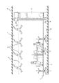
図1は、本実施形態に係る二重床構造1が適用された建物Aを模式的に示す断面図である。図1に示すように、建物Aには、基礎床2と居室空間Xとの間に床下空間Yを備える二重床構造1が採用されている。
建物Aには、このような二重床構造1を用いた加圧式床吹出し空調システムBが採用されている。加圧式床吹出し空調システムBは、オフィス等の居室空間X内の圧力に対して床下空間Y内の圧力を高めることにより、居室空間Xと床下空間Yとの差圧を利用して、床側から空調空気を供給し天井側から排気することにより、居室空間Xの居住域(床パネル上面から100mm〜1700mmの高さ寸法の範囲)の空調を行うシステムである。加圧式床吹出し空調システムBでは、前記居住域内の温度が適正範囲(例えば2℃以内)となるように設計、施工されている。
[First Embodiment]
The
FIG. 1 is a cross-sectional view schematically showing a building A to which a
In the building A, a pressurized floor blowing air conditioning system B using such a
このような加圧式床吹出し空調システムBでは、居室空間X外に設けられた空調機3から床下空間Y内に空調空気を送風し、この送風された空調空気を後述する床パネルに設けられた吹出口Cから居室空間X内に供給する。居室空間X内に供給された空調空気は、居室空間X内の居住者やパソコン等のOA機器類や照明器具等の熱源を冷却して天井側へと上昇し、天井側に設けられた通気口Dから天井裏空間Zを通って空調機3へと戻る。これにより、居室空間X内の空調を行っている。
In such a pressurized floor blowing air conditioning system B, the conditioned air is blown into the underfloor space Y from the
次に、加圧式床吹出し空調システムBに用いる二重床構造1について説明する。
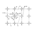
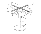
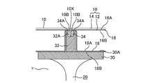
図2は、二重床構造1を平面的に示す模式図である。図3は、二重床構造1を構成する床パネル支持部材を示す斜視図である。図4は、図3におけるIV−IV断面図である。
図2に示すように、二重床構造1は、隣接配置される複数枚の床パネル10と、頂点同士を突き合わせるように隣接配置された4枚の床パネル10の隅角部10Aを支持する複数の床パネル支持部材20とを備えて構成されている。
Next, the
FIG. 2 is a schematic diagram showing the
As shown in FIG. 2, the
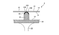
床パネル10は、図2に示すように、平面視正方形状(例えば600mm角や500mm角など)である。また、図4に示すように、床パネル10は、例えば鋼製の床パネル本体12と、床パネル本体12の上面に取り付けられるカーペット等の仕上材14とを備えている。床パネル本体12は、上板16と、下方へ膨出するように断面凹状に形成された下板18とを備え、上板16の下面16Bの外周端縁と下板18の上面18Aの外周端縁とが溶接等により接合されている。仕上材14は、上板16と略同じ平面寸法で形成され、接着剤等により上板16の上面16Aに一体的に取り付けられている。
As shown in FIG. 2, the
また、図4に示すように、隣接する2枚の床パネル10間には、0.3〜0.5mm程度の隙間10Xが形成されている。このような隙間10Xは、床パネル10の着脱を容易にするために積極的に設ける場合もあるが、床パネル10の製造寸法精度や、施工時の位置精度等のために不可避的に発生する。なお、床パネル10には、前記吹出口が設けられているものも用いられている。
As shown in FIG. 4, a
床パネル支持部材20は、図2に示すように、床パネル10の一辺の長さ寸法に相当する間隔で基礎床2(図1)上に複数個が配置されている。また、図3に示すように、床パネル支持部材20は、基礎床2(図1)の上面に当接する例えば円形の当接板22と、当接板22の略中心から垂直に延びる軸部材24と、軸部材24の上端側に嵌挿される支持部材本体26と、支持部材本体26の高さ位置を調整する位置調整部材28とを備えている。なお、当接板22、軸部材24および位置調整部材28が請求項の支持脚に対応する。
As shown in FIG. 2, a plurality of floor
支持部材本体26は、図3,図4に示すように、隣接配置される4枚の床パネル10の下板18の底面18Bを支持する例えば正方形状の床パネル支持板30と、床パネル支持板30の上面30Aにおける略中心位置から各頂点に向かって四方へと延びる4本の腕部32とを備えている。本実施形態では、4本の腕部32の長さ寸法はそれぞれ略同じにしている。
As shown in FIGS. 3 and 4, the support member
各腕部32は、床パネル支持板30の上面30Aよりも一段高く形成されるとともに、各頂点からさらに外側へと延出している。腕部32の高さ寸法は、図4に示すように、床パネル支持板30の上面30Aと腕部32の上面との間の寸法が、床パネル10の下板18の膨出寸法(厚さ寸法)と略同じ寸法となるように形成されている。
また、図3,図4に示すように、各腕部32の上面には、溝部32Aが形成されている。各溝部32Aには、腕部32の上方の隙間10Xから空調空気が漏出することを防止するために、パッキン等の棒状等の可撓性を有する腕部シール材34がそれぞれ取り付けられる。腕部シール材34は、図4に示すように、その上面側が長手方向に沿って中央から2つに分割された2つの当接部34Aを有する。当接部34Aは、隣接する2枚の床パネル10の隣接する一辺である外周端縁10Bにそれぞれ当接し、各床パネル10を支持している。なお、2つの当接部34Aを有する腕部シール材34を一部材として一体的に構成したが、2つの当接部34Aをそれぞれ別体とし二部材としてもよい。
Each
Further, as shown in FIGS. 3 and 4, a
従って、図4に示すように、各床パネル10は、外周端縁10Bがシール材34によって支持されるとともに、下板18の底面18Bが床パネル支持板30によって支持されるため、床パネル10の下側には、基礎床2(図1)から床パネル支持板30までの寸法に相当する床下空間Yが形成されることになる。
Therefore, as shown in FIG. 4, each
また、床パネル支持板30の略中心位置から腕部32の先端までの長さ寸法である持出寸法Sを4倍した値(ここでは、4本の腕部32の長さ寸法の合計値)は、床パネル10の二辺の長さ寸法の合計値(ここでは、一辺の長さ寸法の2倍)よりも小さく、すなわち、2本の腕部32の長さ寸法の合計値が床パネル10の一辺の長さ寸法の合計値よりも小さくなるように形成されている。このため、図2に示すように、隣接する2枚の床パネル10の隣接する一辺の中央には、腕部32上の腕部シール材34によって支持されていない非支持部34Xが設けられることになる。このような非支持部34Xがあることにより、OA機器類等の配線作業が容易になっている。
Further, a value obtained by multiplying the take-out dimension S, which is a length dimension from the substantially center position of the floor
なお、前述したように、隣接する2枚の床パネル10間には隙間10Xが設けられている。このため、シール材34による漏気防止処理がされていない非支持部34Xから、床下空間Yの空調空気が漏出することになる。従って、配線作業の容易化を図りつつも、空調空気の漏出量を必要許容量以下とするために、腕部32の長さ寸法を下記のように設計している。
As described above, the
本加圧式床吹出し空調システムBは、前述したように、床下空間Yと居室空間Xとの差圧を利用して、床パネル10に取り付けた吹出口から空調空気を給気し、居室空間X内の空調を行うシステムである。このような加圧式床吹出し空調システムBにおいて、床下空間Yと居室空間Xとの差圧を15Paとし、500mm角の床パネル10を用いるとともに、隙間10Xの寸法を0.5mmとすると、1時間あたりの漏気量が18m3/h・m2・15Paとなる。また、隙間10Xの寸法を0.4mmとすると1時間あたりの漏気量が12m3/h・m2・15Paとなり、隙間10Xの寸法を0.3mmとすると1時間あたりの漏気量が6.5m3/h・m2・15Paとなる。なお、実際の漏気量には仕上材14の影響も考慮して特定する。
As described above, the pressurized floor blowing air conditioning system B uses the differential pressure between the underfloor space Y and the living room space X to supply conditioned air from the air outlets attached to the
また、加圧式床吹出し空調システムBにおいて、居室空間Xにおける標準的な空調空気循環量(標準循環量)は一般的に16〜50m3/h・m2である。このため、4.0〜15m3/h・m2・15Paの許容される漏気量(漏気許容量)は、標準循環量の25〜30%程度に相当することになる。腕部32の長さ寸法は、漏気許容量が前記範囲を満たすように形成される。
In the pressurized floor blowing air conditioning system B, the standard conditioned air circulation amount (standard circulation amount) in the living room space X is generally 16 to 50 m 3 / h · m 2 . For this reason, the allowable air leakage amount (air leakage allowable amount) of 4.0 to 15 m 3 / h · m 2 · 15 Pa corresponds to about 25 to 30% of the standard circulation amount. The length of the
具体的には、例えば、床パネルが500mm角、隙間10Xの幅寸法が0.4mmで、漏気許容量を6.5m3/h・m2・15Paとした場合には、床パネル10の四辺の長さ寸法の合計が2m(500mm/辺×4辺)であって、漏気量が12m3/h・m2・15Paとなることから、床パネル10の1m2あたりの隙間10Xの長さ寸法は、6.5(m3/h・m2・15Pa)/12(m3/h・m2・15Pa)×2(m)=1.08(m)となる。なお、床パネル10とシール材34とが当接する部分では漏気しないものとする。
これにより、床パネル10の各辺における隙間10Xの長さ寸法、すなわち、非支持部34Xの長さ寸法が1.08(m)/4/2=0.135(m)となる。このため、腕部32の長さ寸法は、床パネル10の一辺の長さ寸法から各辺の隙間10Xの長さ寸法を引いたものを2で除した値、すなわち、(0.5(m)−0.135(m))/2=0.1825(m)となる。なお、隙間10Xの幅を0.3mmや0.5mmとした場合にも同様にして求めることができる。
Specifically, for example, when the floor panel is 500 mm square, the width of the
Thereby, the length dimension of the
以上のようにして、腕部32の長さ寸法を特定することができるが、OA機器用配線などへの利便性や床パネル支持部材20の製造、施工性などを考慮して、非支持部34Xの長さ寸法を最小限0.1m程度確保することが好ましく、例えば、床パネル10が500mm角の場合には腕部32の長さ寸法を最大0.2m程度とし、また、床パネル10が600mm角の場合には腕部32の長さ寸法を最大0.25m程度とすることができる。
Although the length dimension of the
第1実施形態によれば、以下のような効果がある。
(1)隣り合う床パネル支持部材20の腕部32同士を接続せずに、床パネル支持部材20間に非支持部34Xによる所定空間を設けたので、従来のようなストリンガーが存在せず、また、従来のようにストリンガーを着脱する必要がないため、床下空間YでのOA機器類等の配線作業の容易化を図ることができ、居室空間X内のレイアウト変更などが容易となる。このようにストリンガーを用いないため、部材点数を減らすことができ、床パネル支持部材20が安価となる。
According to the first embodiment, there are the following effects.
(1) Since the predetermined space by the
(2)床パネル本体12と仕上材14とを一体的に取り付けて床パネル10を構成したので、床パネル本体12と仕上材14とが別体となる場合に比べて、床パネル10を着脱して、吹出口Cの設けられた床パネル10の位置を変更するだけで、居室空間X内のレイアウト変更を簡単に行うことができる。
(2) Since the
(3)隣接する2枚の床パネル10の隙間10Xからの漏出される空調空気の量を所定量以下となるように腕部32の長さ寸法を特定したので、腕部32の長さ寸法を必要最小限とすることができ経済的である。
(3) Since the length dimension of the
(4)各床パネル10に対応するように腕部シール材34を2つに分割した当接部34Aを形成し、各当接部34Aを各床パネル10毎に当接させたので、床パネル10の製造精度や施工精度が劣って誤差が生じる場合であっても、腕部シール材34の可撓性によって、これらの誤差を吸収でき、漏気防止効果を高めることができる。
(4) Since the
[第2実施形態]
本発明の第2実施形態に係る二重床構造4について説明する。
図5は、本実施形態に係る二重床構造4を示す断面図である。図5に示すように、第2実施形態の二重床構造4は、第1実施形態とは、腕部32および腕部シール材34の構成が相違している。従って、これらの相違点について以下説明する。なお、以下の実施形態では、第1実施形態と同一または相当する構成品には同じ符号を付して、説明を省略または簡略化する。
[Second Embodiment]
A double floor structure 4 according to a second embodiment of the present invention will be described.
FIG. 5 is a cross-sectional view showing the double floor structure 4 according to the present embodiment. As shown in FIG. 5, the double floor structure 4 of the second embodiment is different from the first embodiment in the configuration of the
図5に示すように、二重床構造4の腕部32の上面は曲面状に形成され、第1実施形態のような溝部は形成されていない。腕部32の上面には、腕部シール材として、隣接する床パネル10間を跨る磁気シート等のシート材40が配置されている。このシート材40が隣接する2枚の床パネル10の外周端縁10Bに当接することにより漏気防止が図られている。特に、シート材40として磁気シートを用いた場合において、床パネル10の下板18を鋼製等とすることにより、床パネル10とシート材40とをより密着させることができ、より確実な漏気防止効果を奏することができる。
As shown in FIG. 5, the upper surface of the
第2実施形態によれば、第1実施形態の(1)〜(3)と同様の効果に加えて、以下の効果を奏することができる。
(5)腕部32の上面にシート材40を配置するだけの構成を採用したので、比較的安価で製造できるとともに、製造作業や施工作業が手軽になる。
According to 2nd Embodiment, in addition to the effect similar to (1)-(3) of 1st Embodiment, there can exist the following effects.
(5) Since the configuration in which the
[第3実施形態]
本発明の第3実施形態に係る二重床構造5について説明する。
図6は、二重床構造5を構成する床パネル支持部材を示す斜視図である。図7は、図6におけるVII−VII断面図である。図8は、図6におけるVIII−VIII断面図である。図9は、図6におけるIX−IX断面図である。図6に示すように、第3実施形態の二重床構造5は、第1実施形態とは、床パネル支持部材の構成が相違している。以下、この相違点について詳細に説明する。
[Third Embodiment]
A
FIG. 6 is a perspective view showing a floor panel support member constituting the
前記第1実施形態における図2を利用して説明すると、二重床構造5には、隣接配置される複数枚の床パネル110と、頂点同士を突き合わせるように隣接配置された4枚の床パネル110の隅角部110Aを支持する複数の床パネル支持部材120とが用いられている。
床パネル110は、平面視正方形状(例えば600mm角や500mm角など)であり、図7〜図9に示すように、床パネル本体112と、床パネル本体112の上面112Aに取り付けられる前記仕上材14とを備えている。床パネル本体112は、その下面112Bの外周角部112Cが面取りされている。
Referring to FIG. 2 in the first embodiment, the
The
床パネル支持部材120は、図2に示すように、床パネル110の一辺の長さ寸法に相当する間隔で基礎床2(図1)上に複数個が配置される。また、図6に示すように、床パネル支持部材120は、第1実施形態の床パネル支持部材20と略同様に、前記当接板(図示略)の略中心から垂直に延びる軸部材24と、軸部材24の上端側に嵌挿される支持部材本体126と、支持部材本体126の高さ位置を調整する位置調整部材28とを備えている。
As shown in FIG. 2, a plurality of floor
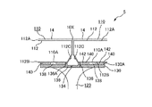
支持部材本体126は、図6に示すように、例えば円形状の床パネル支持板130と、床パネル支持板130の側面130Bから四方へ延びる4本の腕部132とを備える。
床パネル支持板130は、図7〜図9に示すように、隣接する4枚の床パネル110の下面112Bを支持している。また、図6,図7に示すように、床パネル支持板130の上面130Aには、上面130Aの略中心位置から腕部132が延びる方向に沿って四方へと延びる4本の溝部134が形成され、これらの4本の溝部134が平面視十字状となっている。各溝部134には、図6,図7に示すように、幅方向両端部が上方へ突出した突条部136Aを有する断面凹状で棒状の溝部シール材136が取り付けられている。この突条部136Aが床パネル110の下面112Bに当接し、隙間10Xからの漏気を防止している。
As shown in FIG. 6, the support member
As shown in FIGS. 7 to 9, the floor
また、図6に示すように、床パネル支持板130の上面130Aにおいて、各溝部134の間には、上面132Aが平坦に形成され上方へ突出する円板状の突起138がそれぞれ形成されている。つまり、床パネル支持板130の上面130Aには、隣接配置される4枚の各床パネル110の隅角部110A(図2,図7)をそれぞれが支持するように、合計4つの突起138が形成されている。なお、このような突起138を形成する代わりに、突起138と同形状のスペーサを配置してもよい。また、図7に示すように、床パネル支持板130の上面130Aと床パネル110との間には、突起138の突出寸法だけ、突起138の周囲に空隙140が形成される。この空隙140には、比較的柔らかい周囲シール材142が配置され、漏気を防止している。
Further, as shown in FIG. 6, on the
腕部132は、図8に示すように、断面凹状に形成されている。この凹状の底部分にあたる腕部132の上面132Aには、前記溝部シール材136と同様に、幅方向両端部が上方へ突出した突条部144Aを有する断面凹状で棒状の腕部シール材144が取り付けられている。この突条部144Aが床パネル110の下面112Bに当接して、隙間10Xからの漏気防止が図られている。
As shown in FIG. 8, the
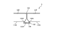
また、図9に示すように、腕部132の先端132Bには、床パネル110の外周角部112Cによって形成された隙間146を塞ぐ断面略三角形状の端部シール材148が取り付けられている。この端部シール材148は、その上面側が中央から2つに分割された2つの当接部148Aを有する。当接部148Aは、対応する各床パネル110の外周角部112Cに当接し、これにより先端132Bからの漏気防止が図られている。
Further, as shown in FIG. 9, an
ここで、前記床パネル支持板130の略中心位置から腕部132の先端132Bまでの長さ寸法である持出寸法Sを4倍した値は、床パネル110の縦横の二辺の長さ寸法の合計値(一辺の長さ寸法の2倍)よりも小さく形成されている。つまり、隣接する2枚の床パネル110の隣接する一辺の中央には、腕部132上の腕部シール材144によって支持されていない非支持部34X(図2)が設けられている。そして、腕部132は、前記第1実施形態の腕部32と同様に、漏気許容量が許容以下量となる長さ寸法で形成されている。
Here, the value obtained by multiplying the take-out dimension S, which is the length dimension from the approximate center position of the floor
第3実施形態によれば、第1実施形態の(1)〜(4)と同様の効果に加えて、以下の効果を奏することができる。
(6)腕部132により、床パネル110の下面112Bを支持する構成としたので、特殊な床パネルを用いることなく一般的な床パネル110を利用でき汎用性を向上できる。
According to 3rd Embodiment, in addition to the effect similar to (1)-(4) of 1st Embodiment, there can exist the following effects.
(6) Since the
[第4実施形態]
本発明の第4実施形態に係る二重床構造6について説明する。
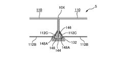
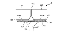
図10は、本実施形態に係る二重床構造6を示す断面図である。図10に示すように、第4実施形態の二重床構造6は、第3実施形態とは、床パネル支持部材120の一部の構成、具体的には、床パネル支持板130の上面130Aに前記突起が形成されていない点と、比較的柔らかい周囲シール材142の代わりに、比較的硬いシート状のシール材150が配置されている点とで相違している。シール材150は、床パネル支持板130の上面130Aにおける溝部134を除く部分に配置され、床パネル110の下面112Bを支持する。
[Fourth Embodiment]
A
FIG. 10 is a cross-sectional view showing the
第4実施形態によれば、第1実施形態の(1)〜(4),(6)と同様の効果に加えて、以下の効果を奏することができる。
(7)比較的硬いシール材150を用いたので、床パネル110からの荷重による変形が小さいことから、十分な耐久性を確保でき、漏気防止効果を持続できる。
According to 4th Embodiment, in addition to the effect similar to (1)-(4), (6) of 1st Embodiment, there can exist the following effects.
(7) Since the relatively hard sealing
[第5実施形態]
本発明の第5実施形態に係る二重床構造7について説明する。
図11は、本実施形態に係る二重床構造7を示す断面図である。図11に示すように、第5実施形態の二重床構造7は、第3実施形態とは、腕部132の上面に取り付けられる腕部シール材144の代わりに、隣接する床パネル110間を跨る磁気シート等のシート材40が配置されている点で相違している。このシート材40が床パネル110の外周端縁に当接することにより漏気防止が図られている。特に、シート材40として磁気シートを用いた場合において、床パネル110の下面112Bを鋼製等とすることにより、床パネル110とシート材40とをより密着させることができ、確実に漏気を防止できる。第5実施形態によれば、第1実施形態の(1)〜(3),(5)と同様の効果を奏することができる。
[Fifth Embodiment]
A double floor structure 7 according to a fifth embodiment of the present invention will be described.
FIG. 11 is a cross-sectional view showing the double floor structure 7 according to the present embodiment. As shown in FIG. 11, the double floor structure 7 of the fifth embodiment is different from the third embodiment between the
なお、本発明は、前記各実施形態に限定されず、本発明の目的を達成できる他の構成等を含み、以下に示すような変形例も本発明に含まれる。
例えば、前記各実施形態において、床パネル10,110を平面視正方形状としたが、長方形状であってもよい。また、前記各実施形態において、床下空間Yから居室空間Xへの漏気許容率を25%としたが、例えば25〜30%の範囲で選択できる。この際、前記各実施形態において、非支持部34Xの長さ寸法が0.1mとなるように、すなわち、床パネル10,110の縦横の二辺の長さ寸法の合計値から持出寸法Sを4倍した値を減じた値が、0.2m以下となるようにしたが、前記漏気許容率を満たす範囲で、その長さ寸法を適宜定めることができる。
また、前記各実施形態において、隣接する2枚の床パネル10の隣接する一辺にそれぞれ当接する2つの当接部34A,136A,144Aを備える各シール材34,136,144を採用したが、隣接する一辺の両方に当接する当接部を1つだけ設けた構成を採用してもよい。
Note that the present invention is not limited to the above-described embodiments, and includes other configurations that can achieve the object of the present invention, and the following modifications are also included in the present invention.
For example, in each of the embodiments described above, the
Further, in each of the above embodiments, the sealing
1,4〜7 二重床構造
2 基礎床
3 空調機
10 床パネル
10A 隅角部
10B 外周端縁
10X 隙間
12 床パネル本体
14 仕上材
16 上板
16A 上面
16B 下面
18 下板
18A 上面
18B 底面
20 床パネル支持部材
22 当接板
24 軸部材
26 支持部材本体
28 位置調整部材
30 床パネル支持板
30A 上面
32 腕部
32A 溝部
34 腕部シール材
34A 当接部
34X 非支持部
40 シート材
110 床パネル
110A 隅角部
112 床パネル本体
112A 上面
112B 下面
112C 外周角部
120 床パネル支持部材
126 支持部材本体
130 床パネル支持板
130A 上面
130B 側面
132 腕部
132A 上面
132B 先端
134 溝部
136 溝部シール材
136A 突条部
138 突起
140 空隙
142 周囲シール材
144 腕部シール材
144A 突条部
146 隙間
148 端部シール材
148A 当接部
150 シール材
A 建物
B 加圧式床吹出し空調システム
C 吹出口
D 通気口
S 持出寸法
X 居室空間
Y 床下空間
Z 天井裏空間
DESCRIPTION OF
Claims (10)
前記基礎床上に立設される支持脚と、
前記支持脚の上部に設けられ、隣接配置される4枚の前記床パネルの各隅角部を支持する床パネル支持板と、
この床パネル支持板から前記1枚の床パネルの隣接辺に沿って延びる4本の腕部と、
前記各腕部の上面に配置され、隣接する2枚の前記床パネルに跨って当接する腕部シール材とを備えることを特徴とする床パネル支持部材。 By supporting a plurality of adjacently arranged floor panels spaced upward from the foundation floor, a double floor structure including an underfloor space for circulating conditioned air between the floor panel and the foundation floor is configured. A floor panel support member for
Support legs erected on the foundation floor;
A floor panel support plate provided on an upper portion of the support leg and supporting each corner portion of the four floor panels disposed adjacent to each other;
Four arms extending from the floor panel support plate along adjacent sides of the one floor panel;
A floor panel support member, comprising: an arm seal member disposed on the upper surface of each arm portion and abutting across two adjacent floor panels.
前記各腕部は、隣接する2枚の前記床パネル間の隙間を介して前記床下空間から居室空間へ漏出する空調空気量が、4.0〜15.0m3/h・m2以下となる長さ寸法で形成されていることを特徴とする床パネル支持部材。 In the floor panel support member according to claim 1,
Each arm portion has an air-conditioning air amount leaking from the underfloor space to the living room space through the gap between the two adjacent floor panels between 4.0 and 15.0 m 3 / h · m 2 or less. A floor panel support member having a length dimension.
前記床パネルの縦横の二辺の長さ寸法の合計値から、前記床パネル支持板の略中心位置から前記腕部の先端までの長さ寸法である持出寸法を4倍した値を減じた値が、0.2m以下であることを特徴とする床パネル支持部材。 In the floor panel support member according to claim 1 or 2,
From the total value of the length dimensions of the vertical and horizontal sides of the floor panel, a value obtained by quadrupling the take-out dimension, which is the length dimension from the approximate center position of the floor panel support plate to the tip of the arm, was subtracted. A floor panel support member having a value of 0.2 m or less.
前記腕部シール材は、隣接する2枚の前記床パネルの隣接する辺ごとにそれぞれが当接する2つの当接部を備えることを特徴とする床パネル支持部材。 In the floor panel support member in any one of Claims 1-3,
The said arm part sealing material is provided with two contact parts which each contact | abuts for every adjacent edge | side of the two said adjacent floor panels, The floor panel support member characterized by the above-mentioned.
前記各腕部は、前記床パネル支持板の略中心位置から四方へと延びるように形成されていることを特徴とする床パネル支持部材。 In the floor panel support member in any one of Claims 1-4,
Each said arm part is formed so that it may extend in four directions from the approximate center position of the said floor panel support plate, The floor panel support member characterized by the above-mentioned.
前記各腕部は、前記床パネル支持板の側面に形成され、
前記床パネル支持板の上面には、前記床パネル支持板の略中心位置から前記腕部が延びる方向に沿って形成された4つの溝部が設けられ、
各溝部の上面には、隣接する2枚の前記床パネルに跨って当接する溝部シール材が配置されていることを特徴とする床パネル支持部材。 In the floor panel support member in any one of Claims 1-4,
Each of the arms is formed on a side surface of the floor panel support plate,
On the upper surface of the floor panel support plate, there are provided four groove portions formed along the direction in which the arm portion extends from a substantially central position of the floor panel support plate,
A floor panel support member, characterized in that a groove sealing material that is in contact with two adjacent floor panels is disposed on the upper surface of each groove.
前記溝部シール材は、隣接する2枚の前記床パネルのそれぞれに当接する2つの当接部を備えることを特徴とする床パネル支持部材。 In the floor panel support member according to claim 6,
The groove part sealing material is provided with two contact parts that contact each of the two adjacent floor panels.
前記床パネル支持板の上面には、隣接配置される4枚の前記床パネルの隅角部をそれぞれ支持する突起が設けられていることを特徴とする床パネル支持部材。 In the floor panel support member according to claim 6 or 7,
The floor panel support member according to claim 1, wherein protrusions are provided on the upper surface of the floor panel support plate to support corners of the four adjacent floor panels.
前記床パネルは、パネル本体と仕上げ材とが一体的に接合されて構成されていることを特徴とする床パネル支持部材。 In the floor panel support member according to any one of claims 1 to 8,
The floor panel is formed by integrally joining a panel body and a finishing material.
A plurality of floor panel support members according to any one of claims 1 to 9, wherein the floor panel support members are installed on a foundation floor so that arms of adjacent floor panel support members are separated from each other, and floor panels are supported by these floor panel support members. A double floor structure characterized in that is supported.
Priority Applications (1)
| Application Number | Priority Date | Filing Date | Title |
|---|---|---|---|
| JP2004108006A JP2005290864A (en) | 2004-03-31 | 2004-03-31 | Floor panel supporting member and double-floor structure |
Applications Claiming Priority (1)
| Application Number | Priority Date | Filing Date | Title |
|---|---|---|---|
| JP2004108006A JP2005290864A (en) | 2004-03-31 | 2004-03-31 | Floor panel supporting member and double-floor structure |
Publications (1)
| Publication Number | Publication Date |
|---|---|
| JP2005290864A true JP2005290864A (en) | 2005-10-20 |
Family
ID=35324110
Family Applications (1)
| Application Number | Title | Priority Date | Filing Date |
|---|---|---|---|
| JP2004108006A Pending JP2005290864A (en) | 2004-03-31 | 2004-03-31 | Floor panel supporting member and double-floor structure |
Country Status (1)
| Country | Link |
|---|---|
| JP (1) | JP2005290864A (en) |
Citations (1)
| Publication number | Priority date | Publication date | Assignee | Title |
|---|---|---|---|---|
| JPH071417Y2 (en) * | 1990-11-30 | 1995-01-18 | 株式会社大林組 | Free access floor for air conditioning |
-
2004
- 2004-03-31 JP JP2004108006A patent/JP2005290864A/en active Pending
Patent Citations (1)
| Publication number | Priority date | Publication date | Assignee | Title |
|---|---|---|---|---|
| JPH071417Y2 (en) * | 1990-11-30 | 1995-01-18 | 株式会社大林組 | Free access floor for air conditioning |
Similar Documents
| Publication | Publication Date | Title |
|---|---|---|
| JP6509340B2 (en) | Heat exchange ventilation system | |
| US5901515A (en) | Raised floor having multiple layers | |
| US6604993B1 (en) | Air partition member and air passageway system | |
| CN210459570U (en) | Wallboard corner connecting piece and modular wall | |
| JP2011149593A (en) | Heat exchange unit | |
| KR101782530B1 (en) | Installation device of light-weight and high-load for access floor panel for a beam | |
| JP2005290864A (en) | Floor panel supporting member and double-floor structure | |
| KR101824701B1 (en) | Frame structure for filter of air conditioner | |
| EP2290171A2 (en) | Free access floor and partitioning method | |
| KR102128462B1 (en) | Casing for industrial air conditions | |
| JP2018119737A (en) | Ceiling-embedded duct type air conditioner | |
| JP2009085467A (en) | Outdoor unit of air conditioner | |
| KR101064556B1 (en) | Airconditioner with frame structure for assembly unlike two casing | |
| JP4302688B2 (en) | Clean room ceiling structure | |
| JP3196233U (en) | Insulation | |
| WO2014109184A1 (en) | Total heat exchanger | |
| WO2023119644A1 (en) | Heat exchanger | |
| JP5616726B2 (en) | Air conditioner mounting structure, building unit and unit building | |
| CN220689244U (en) | Cold air unit | |
| KR101367178B1 (en) | An air conditioner for minimizes heat losses | |
| JP6881833B2 (en) | Floor members and floor air conditioning structure using them | |
| CN217344055U (en) | Laser processing equipment outer cover and laser processing equipment | |
| KR102248314B1 (en) | Assembly structure of ventilation device | |
| JP2006132136A (en) | Acoustic room | |
| JP3064127U (en) | Clean room return chamber floor structure |
Legal Events
| Date | Code | Title | Description |
|---|---|---|---|
| A621 | Written request for application examination |
Free format text: JAPANESE INTERMEDIATE CODE: A621 Effective date: 20070220 |
|
| A977 | Report on retrieval |
Free format text: JAPANESE INTERMEDIATE CODE: A971007 Effective date: 20081113 |
|
| A131 | Notification of reasons for refusal |
Free format text: JAPANESE INTERMEDIATE CODE: A131 Effective date: 20091222 |
|
| A02 | Decision of refusal |
Effective date: 20100413 Free format text: JAPANESE INTERMEDIATE CODE: A02 |