JP2005290861A - Fitment stacking structure and stackable fitment - Google Patents
Fitment stacking structure and stackable fitment Download PDFInfo
- Publication number
- JP2005290861A JP2005290861A JP2004107938A JP2004107938A JP2005290861A JP 2005290861 A JP2005290861 A JP 2005290861A JP 2004107938 A JP2004107938 A JP 2004107938A JP 2004107938 A JP2004107938 A JP 2004107938A JP 2005290861 A JP2005290861 A JP 2005290861A
- Authority
- JP
- Japan
- Prior art keywords
- furniture
- leg
- backing
- panel
- stacking
- Prior art date
- Legal status (The legal status is an assumption and is not a legal conclusion. Google has not performed a legal analysis and makes no representation as to the accuracy of the status listed.)
- Pending
Links
- 238000010276 construction Methods 0.000 claims 1
- 230000002401 inhibitory effect Effects 0.000 abstract 2
- 239000000463 material Substances 0.000 description 93
- 230000002093 peripheral effect Effects 0.000 description 45
- 238000003780 insertion Methods 0.000 description 15
- 230000037431 insertion Effects 0.000 description 15
- 238000006073 displacement reaction Methods 0.000 description 9
- 230000001105 regulatory effect Effects 0.000 description 9
- 210000001364 upper extremity Anatomy 0.000 description 9
- 230000003014 reinforcing effect Effects 0.000 description 7
- 229920003002 synthetic resin Polymers 0.000 description 7
- 239000000057 synthetic resin Substances 0.000 description 7
- 229910000831 Steel Inorganic materials 0.000 description 5
- 239000010959 steel Substances 0.000 description 5
- 238000009434 installation Methods 0.000 description 3
- 229920005989 resin Polymers 0.000 description 2
- 239000011347 resin Substances 0.000 description 2
- 230000000630 rising effect Effects 0.000 description 2
- 101100339481 Cochliobolus miyabeanus HOG1 gene Proteins 0.000 description 1
- 101150009928 SRM1 gene Proteins 0.000 description 1
- 101100454130 Saccharomyces cerevisiae (strain ATCC 204508 / S288c) KSS1 gene Proteins 0.000 description 1
- 238000012986 modification Methods 0.000 description 1
- 230000004048 modification Effects 0.000 description 1
- 238000000465 moulding Methods 0.000 description 1
- 238000005192 partition Methods 0.000 description 1
- 229920003023 plastic Polymers 0.000 description 1
- 238000006116 polymerization reaction Methods 0.000 description 1
- 235000020004 porter Nutrition 0.000 description 1
- 230000001629 suppression Effects 0.000 description 1
- 210000005182 tip of the tongue Anatomy 0.000 description 1
- 125000000391 vinyl group Chemical group [H]C([*])=C([H])[H] 0.000 description 1
- 229920002554 vinyl polymer Polymers 0.000 description 1
- 238000003466 welding Methods 0.000 description 1
Images


Landscapes
- Furniture Connections (AREA)
- Floor Finish (AREA)
- Chairs Characterized By Structure (AREA)
Abstract
Description
本発明は、複数の家具を重合させた際に好適に位置決めし得るスタッキング構造に関するものである。 The present invention relates to a stacking structure that can be suitably positioned when a plurality of furniture is polymerized.
従来、同種の家具同士を重合させて保管または収納の効率化を図るようにし得る種々の家具が存在している。代表的なものとしては、脚折テーブル、折り畳みイス、二重床を構成する床パネル等が挙げられる。脚折テーブルにおいては、脚が天板裏面に折り畳み可能に設けられており、収納時には脚を折り畳んだ状態のテーブルを鉛直方向に積重ねてスタッキングさせている。折り畳みイスにおいても同様に、所定のリンク機構を用いて折り畳んだイス同士を水平方向または鉛直方向に重ね合わせてスタッキングさせている。(例えば、特許文献1参照)また、床パネル(例えば、特許文献2参照)のごとく平板状のものを保管する際は、そのままの形態で鉛直方向に積重ねて保管するのが通例である。
ところが、上述した家具のうち、折り畳みイスにおいては、フレームをスチール製の丸パイプにより構成し、背及び座を合成樹脂または表面をビニールシート等で被覆したクッション材で構成するのが一般的である。したがって、滑りやすい形状及び材質が表面に露出することとなり、積重ねた状態では、背の湾曲を利用してある程度の位置決めを行うものの、イスの長手方向沿って位置ずれが生じやすいという不具合があった。この場合、イスの長手方向の位置ずれを解消させる為に、背の形状を工夫することも考えられるが、座り心地が悪くなったり、折り畳んだ際のイスの厚みが厚くなりスタッキングの効率が低下する等の不具合が考えられる。 However, among the furniture described above, in the folding chair, it is common to configure the frame by a steel round pipe and the back and seat by a synthetic resin or a cushion material whose surface is covered with a vinyl sheet or the like. . Therefore, the slippery shape and material are exposed on the surface, and in the stacked state, although positioning is performed to some extent by using the curvature of the back, there is a problem that misalignment tends to occur along the longitudinal direction of the chair. . In this case, in order to eliminate the positional displacement of the chair in the longitudinal direction, it may be possible to devise the shape of the back, but the seating comfort becomes worse or the thickness of the chair when folded is increased and the efficiency of stacking is reduced There may be a problem such as
また、脚を折り畳んだ状態のテーブルや床パネルのごとくスタッキング時に平板状を成す家具であると、上下に位置する家具同士の係り合う箇所が殆ど無いため、鉛直方向に積重ねた際には水平方向全てに位置ずれを生じやすいといった不具合がある。この為、使用者は、家具同士をスタッキングさせる際に位置ずれが生じないよう慎重に意識しながら積重ねる必要があったり、上位の家具をスタッキング状態から解除する際にも、下位の家具がずれ無いように意識しながら扱う必要があった。 Also, if the furniture is flat like a table or floor panel with the legs folded, there is almost no place where the furniture located above and below is engaged, so the horizontal direction when stacked vertically There is a problem that all are likely to be misaligned. For this reason, the user needs to stack with care so as not to cause misalignment when stacking furniture together, or when lower furniture is released from the stacking state, the lower furniture is displaced. It was necessary to handle it with consciousness not to be.
加えて、これら家具がスタッキング状態にある際に、外部から振動等の衝撃を受けると、スタッキング状態が崩れ、家具が落下するといった畏れもある。 In addition, when these furnitures are in a stacking state, if they receive an impact such as vibration from the outside, the stacking state may collapse and the furniture may fall.
そこで本発明は、以上のような問題に鑑みて、家具をスタッキングさせた際の位置ずれを好適に防止できる家具のスタッキング構造及びスタッキング可能な家具を提供するものである。 Therefore, in view of the above problems, the present invention provides a furniture stacking structure and a stackable furniture that can suitably prevent displacement when the furniture is stacked.
すなわち、本発明に係る家具のスタッキング構造は、第1の家具が、少なくとも所定位置に設けられ使用状態において退避するとともにスタッキング状態において突出する係合部を具備してなり、第1の家具とスタッキングする第2の家具が、前記係合部の対応位置に設けられ少なくとも前記係合部と係わり合う被係合部を具備してなり、前記第1の家具と前記第2の家具とを所定方向にスタッキングさせた際に、前記係合部と前記被係合部とにより前記所定方向とは異なる方向への移動を規制する規制手段を構成することを特徴としている。 That is, the furniture stacking structure according to the present invention includes an engaging portion that is provided at least at a predetermined position and retracts in a use state and protrudes in a stacking state. The second furniture is provided with an engaged portion that is provided at a position corresponding to the engaging portion and is engaged with at least the engaging portion, and the first furniture and the second furniture are arranged in a predetermined direction. When being stacked, the engaging portion and the engaged portion constitute a restricting means for restricting movement in a direction different from the predetermined direction.
このようなものであれば、係合部が使用状態において家具の内部側に退避するとともにスタッキング状態において家具の所定位置から外方へ向けて突出するので、使用時には使用者の邪魔になることもなく違和感を覚えることもない。また、係合部と被係合部との係り合いからなる規制手段の働きによりスタッキングの方向と異なる方向への移動を規制するので、スタッキングを行う際にもスタッキングを解除する際にも過剰に意識せずに自然とスタッキング作業を行える。さらに、スタッキング状態にある家具に何らかの衝撃が加わったとしても位置ずれが起し難くなり、鉛直方向に積重ねた場合でも上位の家具が落下するといったことも有効に回避できる。また、家具同士で規制手段を構成しているので、スタッキング状態にある家具を載せ置いておくポーター等に特段の機能を持たせる必要も無くすることができる。 If this is the case, the engaging portion retracts to the inside of the furniture in the use state and protrudes outward from the predetermined position of the furniture in the stacking state, which may interfere with the user during use. There is no sense of incongruity. In addition, since the movement in the direction different from the stacking direction is restricted by the action of the restricting means consisting of the engagement between the engaging part and the engaged part, it is excessive both when stacking and when releasing stacking. Stacking work can be done naturally without awareness. Furthermore, even if some kind of impact is applied to the furniture in the stacking state, it is difficult for the position shift to occur, and it is possible to effectively avoid the upper furniture falling even when stacked in the vertical direction. In addition, since the regulating means is composed of furniture, it is possible to eliminate the need to give a special function to a porter or the like on which furniture in a stacking state is placed.
係合部が、外力の作用を受け得る荷重受部を具備し、この荷重受部に付与された外力により前記係合部を突出位置から退避位置に変位させるようにすれば、係合片の変位を荷重受部の作用により安定的に行うことが出来る。 If the engaging portion includes a load receiving portion that can receive the action of an external force and the engaging portion is displaced from the protruding position to the retracted position by the external force applied to the load receiving portion, The displacement can be stably performed by the action of the load receiving portion.
この場合、係合部を退避位置から突出位置に常時付勢する付勢手段を設けていれば、使用時には付勢手段の弾性力に抗して荷重受部に外力を作用させることで係合片を退避位置まで変位させておき、家具をスタッキングし得る状態においては荷重受部に作用する外力が解かれることにより係合部が突出位置にまで変位させることができる。 In this case, if an urging means for constantly urging the engaging portion from the retracted position to the protruding position is provided, the engaging portion can be engaged by applying an external force to the load receiving portion against the elastic force of the urging means during use. When the piece is displaced to the retracted position and the furniture can be stacked, the engaging portion can be displaced to the protruding position by releasing the external force acting on the load receiving portion.
荷重受部を、家具を床面に配置した際にこの家具の自重を外力として受け得る位置に設けていれば良い。通常、家具は床面上に配置されるものであるので必然的に生じる家具の自重を利用出来るからである。 What is necessary is just to provide the load receiving part in the position which can receive the own weight of this furniture as external force, when arrange | positioning furniture on a floor surface. This is because the furniture is usually placed on the floor surface, so that the weight of the furniture that is inevitably generated can be used.
家具がその一部または全体を折り畳み可能なものである場合、その折り畳み状態から使用状態への可変動作に関連して荷重受部が外力を受けるようにすれば、家具の可変動作以外の特別な作業を行うことなく係合部を突出位置にまで変位させることが出来る。 If the furniture is foldable partly or entirely, if the load receiving part receives external force in relation to the variable operation from the folded state to the used state, a special operation other than the variable operation of the furniture is possible. The engaging portion can be displaced to the protruding position without performing work.
係合部及び被係合部の好適な具体例としては、係合部が、先端側に設けられ前記被係合部と係り合う係合片と、基端側において家具の所定位置に支持され該係合片を突出位置と退避位置との間で変位可能にする基端部とを備えていれば良く、被係合部は、係合片を挿入可能な穴部からなるものが挙げられる。 As a preferred specific example of the engaging portion and the engaged portion, the engaging portion is supported at a predetermined position of the furniture on the proximal end side with an engaging piece that is provided on the distal end side and engages with the engaged portion. It is only necessary to include a base end portion that allows the engagement piece to be displaced between the protruding position and the retracted position, and the engaged portion includes a hole portion into which the engagement piece can be inserted. .
また、係合部及び被係合部を同一の家具に共に備えておけば3つ以上の家具をスタッキングが可能となる。 Further, if both the engaging portion and the engaged portion are provided in the same furniture, it is possible to stack three or more furniture.
本発明によれば、使用者はスタッキング作業及びスタッキング解除作業を簡易に行うことが出来るとともに、スタッキング状態にある家具群の位置ずれの発生を抑制し安定した状態でスタッキングを維持出来る。 According to the present invention, the user can easily perform the stacking work and the stacking release work, and can suppress the occurrence of positional deviation of the furniture group in the stacking state and maintain the stacking in a stable state.
以下、本発明の一実施形態を、図面を参照して説明する。 Hereinafter, an embodiment of the present invention will be described with reference to the drawings.
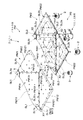
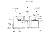
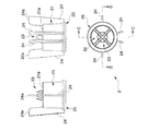
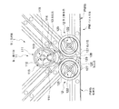
本発明に係るスタッキング構造を実現可能な家具たる床パネルPは、図1、図2などに示すように、平面視略正方形状のパネル本体PMと、このパネル本体PMを支持する支持脚PSとからなるものである。この支持脚PSは、隣接する単位パネルのコーナー部が集合する部位を支持する第1支持脚1と、パネル本体PMの四つの隅部をそれぞれ支持する第2支持脚2と、パネル本体PMの略中央部を支持する第3支持脚3とを備えたものである。そして、パネル本体PMに、支持脚PS(第1支持脚1、第2支持脚2及び第3支持脚3)を予め取付けた状態で、当該床パネルPを、例えば、建築床面FL(図14、図15参照。)に複数並べて敷設することにより、パネル本体PMと建築床面FLとの間にコード類を配線可能な二重床としての機能を発揮するようにしている。
As shown in FIGS. 1 and 2, the floor panel P that is a furniture capable of realizing the stacking structure according to the present invention includes a panel body PM having a substantially square shape in plan view, and support legs PS that support the panel body PM. It consists of The support leg PS includes a
より具体的に各部を説明する。 Each part will be described more specifically.
パネル本体PMは、所定部位に形成した分画開口部によって分画された複数の単位パネルを有するものであり、概略平板状の表材PM1と、この表材PM1の下面側に位置する裏材PM2とを重合させるとともに、これら表材PM1と裏材PM2とを後述する適宜の手段で一体的に連結したものとしている。 The panel main body PM has a plurality of unit panels that are fractionated by a fractional opening formed in a predetermined portion, and is a substantially flat surface material PM1 and a backing material that is located on the lower surface side of the surface material PM1. While PM2 is polymerized, the front material PM1 and the back material PM2 are integrally connected by an appropriate means described later.
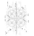
さらに、この表材PM1と裏材PM2とについて説明すると、表材PM1は、薄板状のスチール素材を塑性変形加工することにより形成されたものであり、4つの辺に囲まれた平面視略正方形状をなす面板部PM1aと、この面板部PM1aの各辺から垂下して設けた側縁部PM1bとを備えている。面板部PM1aには、各辺の中点X1から面板部PM1aの中心部に向かって所定距離延びる被係合部Uとして機能する穴部たる第1表材スリットSL1aと、隣り合う第1表材スリットSL1aの内方端部(面板部PM1aの中心側に位置する端部)同士を結ぶ線に沿って延びる第2表材スリットSL1bとを形成するとともに、これら第1表材スリットSL1a及び第2表材スリットSL1bにより分画開口部たる表材分画開口部SL1を構成し、この表材分画開口部SL1によって一枚の表材PM1が複数の単位パネル(1つの第1表材単位パネルPM11及び4つの第2表材単位パネルPM12)に分画されるようにしている。具体的には、第1表材単位パネルPM11は、4つの第2表材スリットSL1bに囲まれ、面板部PM1aの中央部に位置する平面視略正方形状のものである。第2表材単位パネルPM12は、1つの第2表材スリットSL1b、この第2表材スリットSL1bの両端からそれぞれ延びる第1表材スリットSL1a及びこれら各第1表材スリットSL1aの外方端部(面板部PM1aの反中心側に位置する端部)から第2表材スリットSL1bに対向する表材PM1のコーナー部に向かって延びる2つの辺PM121によって囲まれ、表材PM1の隅部を構成するようにした平面視略五角形状のものである。なお、各第2表材スリットSL1bの略中間部位には、表材PM1の肉厚方向に貫通していない接続部たる表材接続部PM1Xを設け、この表材接続部PM1Xにより第1表材単位パネルPM11と第2表材単位パネルPM12とが一部において連続するようにしている。また、各側縁部PM1bの中央部には、前記第1表材スリットSL1aの外方端部から側縁部PM1bに下方に向かって延びる第3表材スリットSL1cを形成している。また、各第2表材単位パネルPM12には、後述する裏材PM2に設けた突部PM22Tを収容し得る収容部PM12Sを形成してある。これら突部PM22Tと収容部PM12Sとが、位置ずれ抑制手段としての機能を発揮する。
各収容部PM12Sは、本実施形態では、下方に窪ませてなる平面視円形状の有底のものとしているが、例えば、貫通させた無底のものなど、これに限られない。
Further, the front material PM1 and the back material PM2 will be described. The front material PM1 is formed by plastic deformation of a thin steel material, and is substantially square in plan view surrounded by four sides. A face plate portion PM1a having a shape and a side edge portion PM1b provided to hang from each side of the face plate portion PM1a are provided. The face plate portion PM1a has a first surface material slit SL1a that is a hole functioning as an engaged portion U that extends a predetermined distance from the middle point X1 of each side toward the center portion of the face plate portion PM1a, and an adjacent first surface material. A second surface material slit SL1b extending along a line connecting the inner end portions of the slit SL1a (the end portion positioned on the center side of the face plate portion PM1a) is formed, and the first surface material slit SL1a and the second surface material slit SL1a A surface material fraction opening SL1 which is a fraction opening is formed by the surface material slit SL1b, and one surface material PM1 is composed of a plurality of unit panels (one first surface material unit panel) by the surface material fraction opening SL1. PM11 and four second surface material unit panels PM12). Specifically, the first surface material unit panel PM11 is surrounded by four second surface material slits SL1b and has a substantially square shape in plan view located at the center of the face plate portion PM1a. The second surface material unit panel PM12 includes one second surface material slit SL1b, a first surface material slit SL1a extending from both ends of the second surface material slit SL1b, and outer ends of the first surface material slits SL1a. Surrounded by two sides PM121 extending toward the corner portion of the surface material PM1 facing the second surface material slit SL1b from the end portion located on the opposite side of the face plate portion PM1a, the corner portion of the surface material PM1 is configured. The plan view has a substantially pentagonal shape. In addition, the surface material connection part PM1X which is a connection part which has not penetrated in the thickness direction of the surface material PM1 is provided in a substantially intermediate portion of each second surface material slit SL1b, and the first surface material is formed by the surface material connection part PM1X. The unit panel PM11 and the second surface material unit panel PM12 are partially continuous. Further, a third surface material slit SL1c extending downward from the outer end portion of the first surface material slit SL1a to the side edge portion PM1b is formed at the center of each side edge portion PM1b. Each second front material unit panel PM12 is formed with a housing part PM12S capable of housing a protrusion PM22T provided on a back material PM2 described later. These protrusions PM22T and the housing part PM12S exhibit a function as a positional deviation suppression means.
In the present embodiment, each housing portion PM12S has a bottomed shape with a circular shape in plan view that is recessed downward, but is not limited to this, for example, a bottomless one that is penetrated.
一方、裏材PM2は、薄板状のスチール素材を塑性変形加工することにより形成されたものであり、4つの辺によって囲まれた平面視略正方形状をなし、前記表材分画開口部SL1の投影位置に沿う位置に分画開口部たる裏材分画開口部SL2を形成している。具体的には、各辺の中点X2から裏材PM2の中心部に向かって所定距離延びる第1裏材スリットSL2aと、隣り合う第1裏材スリットSL2aの内方端部(裏材PM2の中心側に位置する端部)同士を結ぶ線に沿って延びる被係合部Uとして機能する穴部たる第2裏材スリットSL2bとを形成し、これら第1裏材スリットSL2a及び第2裏材スリットSL2bにより裏材分画開口部SL2を構成し、この裏材分画開口部SL2によって一枚の裏材PM2が複数の単位パネル(1つの第1裏材単位パネルPM21及び4つの第2裏材単位パネルPM22)に分画されるようにしている。具体的には、第1裏材単位パネルPM21は、4つの第2裏材スリットSL2bに囲まれ、裏材PM2の中央部に位置する平面視略正方形状のものである。第2裏材単位パネルPM22は、1つの第2裏材スリットSL2b、この第2裏材スリットSL2bの両端からそれぞれ延びる第1裏材スリットSL2a及びこれら各第1裏材スリットSL2aの外方端部(裏材PM2の反中心側に位置する端部)から第2裏材スリットSL2bに対向する裏材PM2のコーナー部に向かって延びる2つの辺PM221によって囲まれ、裏材PM2の4つの隅部にそれぞれ位置する平面視略五角形状のものである。なお、各第2裏材スリットSL2bの略中間部位に、裏材PM2の肉厚方向に貫通していない接続部たる裏材接続部PM2Xを設け、この裏材接続部PM2Xにより第1裏材単位パネルPM21と第2裏材単位パネルPM22とをそれぞれ一部において連続させている点も表材PM1と同様である。 On the other hand, the backing PM2 is formed by plastically deforming a thin steel material, has a substantially square shape in plan view surrounded by four sides, and is formed on the surface material partition opening SL1. A backing fraction opening SL2 that is a fraction opening is formed at a position along the projection position. Specifically, the first backing slit SL2a extending a predetermined distance from the middle point X2 of each side toward the center of the backing PM2, and the inner end portion of the adjacent first backing slit SL2a (of the backing PM2) A second backing slit SL2b which is a hole functioning as an engaged portion U extending along a line connecting the ends) located on the center side, and the first backing slit SL2a and the second backing The slit SL2b constitutes a backing fraction opening SL2, and the backing fraction opening SL2 allows one backing PM2 to be divided into a plurality of unit panels (one first backing unit panel PM21 and four second backings). The material unit panel PM22) is divided. Specifically, the first backing unit panel PM21 is surrounded by four second backing slits SL2b and has a substantially square shape in plan view located at the center of the backing PM2. The second backing unit panel PM22 includes one second backing slit SL2b, a first backing slit SL2a extending from both ends of the second backing slit SL2b, and an outer end portion of each of the first backing slit SL2a. The four corners of the backing PM2 are surrounded by two sides PM221 extending from (the end located on the opposite side of the backing PM2) to the corner of the backing PM2 facing the second backing slit SL2b. Are substantially pentagonal in plan view. A backing material connection part PM2X, which is a connection part that does not penetrate in the thickness direction of the backing material PM2, is provided at a substantially intermediate portion of each second backing material slit SL2b, and a first backing material unit is provided by this backing material connection part PM2X. The point that the panel PM21 and the second backing unit panel PM22 are partially continuous is also the same as the surface material PM1.
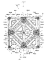
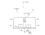
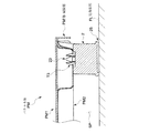
しかして、裏材PM2は、表材PM1と重合させた状態において、図2に示すように、表材PM1の下面側に密接する平板部PM2mと、裏材PM2の強度を確保すべく絞り加工により溝状に形成された補強部PM2nと、裏材PM2の裏面側に設けられ前記支持脚PSを取付け得る取付口Tを有し、部分的に凹凸形状をなすように形成されている。具体的には、平板部PM2mについては、第1裏材単位パネルPM21及び各第2裏材単位パネルPM22の各周縁部と、第1裏材単位パネルPM21及び各第2裏材単位パネルPM22の中央部位を平板部PM2mとしている。なお、その平板部PM2mのうち、各第2裏材単位パネルPM22の略中央部の平板部PM2mは、平面視略三角形状をなすものとし、また、第1裏材単位パネルPM21の略中央部に対向させるようにして設けた4つの平板部PM2mは、それぞれ平面視略三角形状をなすものとしている。一方、補強部PM2nについては、第1裏材単位パネルPM21及び各第2裏材単位パネルPM22の各周縁部位に沿った所定部位を、補強部PM2nとしている。ここで、その所定部位とは、第1裏材単位パネルPM21の略中央部に対向させるようにして設けた4つの平板部PM2mに係るものについては、それぞれの平板部PM2mが、他の平板部PM2m及び第1裏材単位パネルPM21の周縁部に対して側面視略凹溝状に接続される部位としている。また、各第2裏材単位パネルPM22の略中央部の平板部PM2mに係るものについては、その平板部PM2mが、第2裏材単位パネルPM22の周縁部に対して側面視略凹溝状に接続される部位としている。 Thus, the backing material PM2 is drawn to ensure the strength of the backing material PM2 and the flat plate portion PM2m in close contact with the lower surface side of the backing material PM1, as shown in FIG. And a mounting portion T provided on the back side of the backing material PM2 to which the support leg PS can be attached, and is formed to have a partially uneven shape. Specifically, for the flat plate portion PM2m, the peripheral portions of the first backing unit panel PM21 and each second backing unit panel PM22, and the first backing unit panel PM21 and each second backing unit panel PM22. The central part is a flat plate portion PM2m. Of the flat plate portions PM2m, the flat plate portion PM2m at the substantially central portion of each second backing unit panel PM22 has a substantially triangular shape in plan view, and the substantially central portion of the first backing unit panel PM21. The four flat plate portions PM2m provided so as to face each other have a substantially triangular shape in plan view. On the other hand, for the reinforcing part PM2n, a predetermined part along each peripheral part of the first backing unit panel PM21 and each second backing unit panel PM22 is defined as a reinforcing part PM2n. Here, with respect to the four portions of the flat plate portion PM2m provided so as to be opposed to the substantially central portion of the first backing unit panel PM21, the predetermined portion is the other flat plate portion. It is set as the site | part connected by the side view substantially concave groove shape with respect to the peripheral part of PM2m and 1st backing unit panel PM21. Moreover, about the thing which concerns on flat plate part PM2m of the approximate center part of each 2nd backing material unit panel PM22, the flat plate part PM2m is a side view substantially concave groove shape with respect to the peripheral part of 2nd backing material unit panel PM22. It is a connected part.
また、取付口Tについては、図1、図2に示すように、第1裏材単位パネルPM21の各コーナー部に後述する第1支持脚1の第1突起部113が取付可能な第1取付口T1を形成するとともに、第1裏材単位パネルPM21の中央に後述する第3支持脚3が取付可能な第4取付口T4を形成してある。一方、第2裏材単位パネルPM22の各コーナー部のうち、第1裏材単位パネルPM21及び他の第2裏材単位パネルPM22に隣接するコーナー部に後述する第1支持脚1の第2突起部123が取付可能な第2取付口T2を形成するとともに、第1裏材単位パネルPM21及び他の第2裏材単位パネルPM22に隣接しないコーナー部、すなわち裏材PM2の四隅の隅部に後述する第2支持脚2が取付可能な第3取付口T3を形成してある。これら第1取付口T1、第2取付口T2、第3取付口T3及び第4取付口T4(以下、取付口Tと総称する。)は、何れも補強部PM2nの前記面板部PM1a対して平行な面に形成され、その面の肉厚方向に貫通している。第1取付口T1、第3取付口T3及び第4取付口T4は、平面視円形状をなし、第2取付口T2のみが、平面視長円形状をなすようにしている。なお、平面視長円形状を成す取付口は、分画開口部の長手方向と直交する方向に、その長手寸法を有するものであれば良い。すなわち、本実施形態では、第2取付口T2が、裏材PM2に設けた複数の第2裏材スリットSL2bのうち、当該第2取付口T2に最も近接している第2裏材スリットSL2bの長手方向と直交する方向に、長手寸法を有するようにしている(図16参照。)。
In addition, as shown in FIGS. 1 and 2, the attachment port T is a first attachment in which a
また、複数のパネル本体PMのみを積み重ねて収納などする際に、それら複数のパネル本体PMのスタッキング(図18参照。)をも好適に行うために、第2裏材単位パネルPM22には、前記表材PM1の第2表材単位パネルPM12に形成した収容部PM12Sと対応する箇所に、その収容部PM12Sに収容され得る突部PM22Tを複数設けている(図1、図2参照。)。各突部PM22Tは、補強部PM2nよりもさらに下方に突出させたものであり、本実施形態においては、4つの第2裏材単位パネルPM22のうち、裏材PM2の対角線状線上に位置する一対の第2裏材単位パネルPM22にそれぞれ突部PM22Tを設けている(図2参照。)。 Further, when stacking and storing only a plurality of panel main bodies PM, the second backing unit panel PM22 includes the above-described second backing unit panel PM22 in order to suitably stack the panel main bodies PM (see FIG. 18). A plurality of protrusions PM22T that can be housed in the housing portion PM12S are provided at locations corresponding to the housing portion PM12S formed in the second surface material unit panel PM12 of the surface material PM1 (see FIGS. 1 and 2). Each protrusion PM22T protrudes further downward than the reinforcing part PM2n. In the present embodiment, of the four second backing unit panels PM22, a pair positioned on the diagonal line of the backing PM2. Each of the second backing unit panels PM22 is provided with a protrusion PM22T (see FIG. 2).
これら表材PM1の下面側と裏材PM2の上面側とを重合させて、複数箇所を適宜の手段(例えば、スポット溶接など)で連結することにより、表材PM1と裏材PM2とを一体的に組み付けてなる一のパネル本体PMが形成される。このパネル本体PMは、表材PM1と裏材PM2とを組み付けた状態において、第1表材単位パネルPM11と第1裏材単位パネルPM21とが重合するとともに、各第2表材単位パネルPM12と各第2裏材単位パネルPM22とが重合し、表材PM1及び裏材PM2それぞれに形成した表材分画開口部SL1及び裏材分画開口部SL2(以下、分画開口部SLと総称する。)を介して上述した重合関係にある第1表材単位パネルPM11と第1裏材単位パネルPM21とが第1単位パネルとして、また、各第2表材単位パネルPM12と各第2裏材単位パネルPM22とが第2単位パネルとして、おのおの同時に変形するように設定している。しかして、このパネル本体PMは、分画開口部SLを介して隣接する第1単位パネルと第2単位パネルとを相対変位させ得るように構成されている。そして、隣接する第1単位パネルと第2単位パネルと(以下、第1単位パネルと第2単位パネルとを「単位パネル」と総称する。)のコーナー部同士が集合する部位(以下、コーナー部集合部位とする。)に、後述する第1支持脚1を取り付けることができるようにしている。
By superposing the lower surface side of the front material PM1 and the upper surface side of the back material PM2 and connecting a plurality of locations by appropriate means (for example, spot welding), the front material PM1 and the back material PM2 are integrated. One panel main body PM assembled to is formed. In the panel body PM, in a state where the front material PM1 and the back material PM2 are assembled, the first front material unit panel PM11 and the first back material unit panel PM21 are superposed, and each second front material unit panel PM12 Each of the second backing unit panels PM22 is polymerized to form a front material fraction opening SL1 and a backing material fraction opening SL2 (hereinafter collectively referred to as a fraction opening SL) formed in the front material PM1 and the back material PM2, respectively. The first front panel unit panel PM11 and the first back panel unit panel PM21, which are in the above-described polymerization relationship via the above-described), serve as the first unit panel, and each second front panel unit panel PM12 and each second back panel. The unit panel PM22 is set as a second unit panel so as to be simultaneously deformed. Thus, the panel body PM is configured to be able to relatively displace the first unit panel and the second unit panel which are adjacent to each other through the fraction opening SL. And the part (henceforth a corner part) where the corner parts of the adjoining 1st unit panel and 2nd unit panel (henceforth a 1st unit panel and a 2nd unit panel are named generically "unit panel") gather. The
さらに、本実施形態では、単位パネルに形成した第1取付口T1、第2取付口T2に、第1支持脚1に設けた第1突起部113、第2突起部123を取り付けた際に、それら突起部と取付口の嵌め合いにより単位パネル同士の相対位置を許容する許容手段を構成するようにしている。具体的には、第1取付口T1と第1突起部113は緊密に取付け、第2取付口T2と第2突起部123は遊嵌した状態で取付られるようにして構成している。すなわち、この取付状態において前記単位パネル同士の相対変位に伴って前記第2突起部123と前記第2取付口T2との相対位置が変化することにより、単位パネル同士の相対位置を許容する許容手段としての機能を発揮する。
Furthermore, in this embodiment, when the
第1支持脚1は、図3、図4、図5、図6、図7、図8、図16等に示すように、コーナー部集合部位に隣接する各単位パネルの枚数に対応して設けた複数の脚本体と、これら脚本体同士を連結する連結部13とを備えたものである。また、本実施例では、係合部Kをこの第1支持脚1に設けている。すなわち、第1支持脚1に、後述する基端側を支持される基端部と後述する被係合部Uに係り合う係合片と後述する荷重受部とを備えた、係合部Kを設けてなり、係合片を第1支持脚1の下面より突出する突出位置と、第1支持脚の下面より突出しない退避位置とに取り得るようにしている。
As shown in FIGS. 3, 4, 5, 6, 7, 8, 8, and 16 etc., the
より、具体的に第1支持脚1は、例えば合成樹脂素材からなる一体成形品であり、コーナー部集合部位における第1裏材単位パネルPM21のコーナー部周辺を支持し得る第1脚本体11と、コーナー部集合部位において第1裏材単位パネルPM21に隣接する第2裏材単位パネルPM22のコーナー部周辺を支持し得る一対の第2脚本体12と、これら各脚本体を一体に連結する連結部13とを備えている。なお、本実施形態では、これら各脚本体11、12の中心部同士を結ぶ線分が第1脚本体11の中心部を頂点とする平面視略二等辺三角形状となるように各脚本体11、12を配置している(図4参照。)。またこのとき、一対の第2脚本体12を、当該床パネルPを平面視した際に、後述する位置決め手段がパネル本体PMから突出する位置に位置付けられるように、パネル本体PMの側縁部PM1bに沿って配置するようにしている。また、第1脚本体11、第2脚本体12及び連結部13を合成樹脂により一体的に成形している。なお、第1脚本体11及び第2脚本体12の後述する各接地部と、連結部13のそれぞれを軟質樹脂にて成形しても良い。この場合、2色(異材質)成形を採用すると効果的である。
More specifically, the
以下、各部についてより具体的に説明すると、第1脚本体11は、概略円筒状をなす第1周壁部111と、第1周壁部111の内周に平面視略十字状に設けられ第1周壁部111と略同じ高さ寸法を有する第1リブ112と、第1リブ112同士が交叉する部位に関連付けて設けられ第1周壁部111の上端より上方に突出させてなる突起部たる第1突起部113とを有する。この第1突起部113は、前記裏材PM2の第1裏材単位パネルPM21のコーナー部に形成した第1取付口T1に係合可能なものであり、第1突起部113の軸中心を中心として十字状をなすように形成したスリット113Sと、このスリット113Sを挟むように配置した弾性変形し得る4つの弾性部1131とを備えている。そして、各弾性部1131には、その先端部に鉤状の係合片1131aを一体に備えるようにしている。また、第1周壁部111と第1リブ112との間には、後述する高さ調節部材たる第1ライナーR1に設けた第1挿入部が挿入可能な概略円筒状をなす挿入穴たる第1挿入穴11Xを設けている。さらに、第1周壁部111の外周には、第2脚本体12側に向かって延出させてなる一対の鍔部114を設けている。そして、この鍔部114の上端が、第1周壁部111の上端及び突起部の上端よりもさらに上方に位置するように設定している。また、第1周壁部111の下端部における径が第1周壁部111の他の部位より若干大径となるように設定するとともに、この第1周壁部111の下端側に、建築床面FLに接地し得る円環状の接地部たる第1接地部115を設けている。さらにまた、本実施形態では、この第1周壁部111の高さ寸法と、後述する第2支持脚2を構成する隅部支持用周壁部21の高さ寸法と、後述する第3支持脚3の中央支持用周壁部31の高さ寸法とを、略同一に構成している。
Hereinafter, each part will be described in more detail. The
一方、各第2脚本体12は、概略円筒状をなし前記第1脚本体11の第1周壁部111より大きい高さ寸法を有する第2周壁部121と、第2周壁部121の内周に平面視略十字状に設けられ前記第1周壁部111と略同じ高さ寸法を有する第2リブ122と、第2リブ122同士が交叉する部位に関連付けて設けられ第2リブ122の上端より上方に突出させてなる突起部たる第2突起部123とを有する。
On the other hand, each second leg
さらに詳述すると、第2周壁部121は、その上縁が前記第1脚本体11の鍔部114の上縁と略同じ高さ位置となるように設定されており、第2周壁部121の一部に第2リブ122の上縁と略同じ高さ位置まで切り欠いてなる切欠部124を形成してある。そして、各第2脚本体12をそれぞれ対応する第2裏材単位パネルPM22のコーナー部に取り付けた場合に、第2周壁部121の上縁が第2裏材単位パネルPM22の平板部PM2mに当接するとともに、切欠部124によって第2周壁部121の上縁と第2裏材単位パネルPM22の補強部PM2nとの干渉を回避し、切欠部124に第2裏材単位パネルPM22の補強部PM2nが位置するように設定している。
More specifically, the second
第2突起部123は、前記裏材PM2の第2裏材単位パネルPM22のコーナー部に形成した第2取付口T2に係合可能なものであり、前記第1脚本体11の第1突起部113と略同様の形状をなすものである。
The
加えて、本実施形態では、第2周壁部121の下端部に第2周壁部121の他の部位より若干大径となるように設定している。そして、この第2周壁部121の下端側に、建築床面FLに接地し得る接地部たる第2接地部125を形成するとともに、第2周壁部121の外周に他方の第2脚本体12に向かって延出させてなる概略板状の延出部126を設けている。各延出部126は第2リブ122よりも小さい高さ寸法を有し、これら各延出部126に、前記第1脚本体11から離れる方向に概略板状の突出部127を重合するように設け、これら突出部127が各第2脚本体12の第2接地部125の外縁同士を結んた線分よりも前記第1脚本体11から離れる方向に突出するように設定している。そして、本実施形態においては、突出部127の正面視における巾寸法d1(延出部126の延出方向に沿った寸法)を、延出部126の正面視における巾寸法d2の略半分に設定し(図4参照。)、一方の第2脚本体12の延出部126には、突出部127を延出部126の基端部側に設け、他方の第2脚本体12の延出部126には、突出部127を延出部126の先端部に設けている。これにより、一対の第1支持脚1を第2脚本体12同士が当接するように対向配置した場合、対応する突出部127同士が延出方向に隣接し、第1支持脚1を、延出部126の延出方向へ相対移動することが禁止される。このように、各延出部126は、当該床パネルPの位置決めを行う位置決め手段(特に、隣接配置した床パネルP同士が所定位置よりさらに近接することを禁止する近接禁止手段)としての機能を発揮する。また、各突出部127は、当該床パネルPの位置決めを行う位置決め手段(特に、隣接配置した床パネルP同士が、それらのパネル本体PMの側縁部PM1b同士を略沿わせた状態で、所定位置よりさらに延出部126の延出方向に沿ってずれ動くことを禁止するずれ移動禁止手段)としての機能を発揮する。
In addition, in the present embodiment, the lower end portion of the second
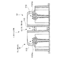
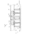
ここで、パネル本体PMに支持脚PSを取付けた状態の床パネルP同士をスタッキングする際のスタッキング構造について説明する。本発明に係るスタッキング構造は、上位に位置する第1のパネルが有する係合部Kと、下位に位置する第2のパネルが有する被係合部Uとで、水平方向の位置ずれを規制する規制手段Fを構成している。詳述すると、第1支持脚1の係合部Kは、一方の第2脚本体12の第2周壁部121に設定した前記第2接地部125に基端部と、この基端部から他方の第2脚本体12に向かって延出する概略薄板状の係合片たる舌片部128とを一体に設けている。舌片部128は、その先端部下面に下方に向かって所定寸法突出させた突起129を有しており(図3、図5、図8参照。)、図19に示すように、この突起129を、下段側に位置付けたパネル本体PM(本願請求項1の第2の家具)の係合部の対応位置に設けた被係合部Uたる第1表材スリットSL1a(第1裏材スリットSL2a)に挿入して、床パネルP同士を上下にスタッキング可能に構成している。なお、舌片部128はそれ自体がある程度の弾性を有するものであり付勢手段として機能する。第1支持脚1を建築床面FL等に接地させた場合、第1支持脚1の最下位に位置する突起129が他の部位より優先して接地するが、床パネルP自体の自重により突起129の突出寸法に対応して舌片部128の先端部が上方に浮き上がるように弾性変形可能に設定してある。すなわち、本実施例においては、突起129が荷重受部としても機能することとなり、荷重受部が床パネルPの自重による作用を受けない状態(床パネルPを建築床面FL等に接地させない状態)では、係合片が床パネルPの下面より下方に突出する突出位置をとり、荷重受部が床パネルPの自重による作用を受ている状態(床パネルPを建築床面FL等に接地させた状態)では、係合片は床パネルPより突出しない退避位置に変位することとなる。具体的には、第2脚本体12間に係合片たる突起129が退避することなる。しかして、下段側のパネル本体PMの第1表材スリットSL1a(第1裏材スリットSL2a)に対して、上段側の第1支持脚1に設けた突起129が挿入されることで規制手段を構成するので、複数の床パネルPを積み重ねた状態で、例えば水平方向に外力が加わったとしても、第1表材スリットSL1a(第1裏材スリットSL2a)と突起129とによって、積み重ねている状態が崩れることを効果的に防止することができる。特に、本実施例においては、第1表材スリットSL1a(第1裏材スリットSL2a)をパネル本体PMの各片からパネル本体PMの中央に向かって延びるように設けるとともに、突起129も各々対応する第1表材スリットSL1a(第1裏材スリットSL2a)延びる方向に沿って設けているので水平方向全てにおいて位置ずれを規制することができる。
Here, the stacking structure when stacking the floor panels P with the support legs PS attached to the panel body PM will be described. The stacking structure according to the present invention regulates the displacement in the horizontal direction between the engaging portion K of the first panel positioned at the upper level and the engaged portion U of the second panel positioned at the lower level. The regulating means F is configured. More specifically, the engagement portion K of the
第2支持脚2は、図1に示すように、パネル本体PMのコーナー部であって且つ前記単位パネルが隣接しない部位において、前記建築床面FLに接地しながら前記パネル本体PMを支持するものである。なお、図示はしていないが、当該第2支持脚2と建築床面FLとの間に、床面の高さ調節をするための高さ調節部材たる第2ライナー(図示せず)を設け、当該第2支持脚2が建築床面FLに対して直接接しないようにしてもよい。
As shown in FIG. 1, the
より具体的にこの第2支持脚2は、図9、図10、図11、図15などに示すように、概略円筒状をなす隅部支持用周壁部21と、隅部支持用周壁部21の内周に平面視略十字状に設けられ隅部支持用周壁部21と略同じ高さ寸法を有する隅部支持用リブ22と、隅部支持用リブ22同士が交叉する部位に関連付けて設けられ隅部支持用周壁部21の上端より上方に突出させてなる突起部たる隅部支持用突起部23と、前記隅部支持用周壁部21の外周に設けた4枚の隅部支持用羽根部24とを具備し、これら各部を合成樹脂により一体に形成した一体成形品である。
More specifically, as shown in FIGS. 9, 10, 11, and 15 and the like, the
さらに各部を詳述すると、隅部支持用周壁部21は、その上端部に、当該第2支持脚2を前記パネル本体PMに取り付けた状態において前記裏材PM2の前記補強部PM2nを支持し得る第1支持部21aを有している。また、隅部支持用周壁部21の下端部における径が隅部支持用周壁部21の他の部位より若干大径となるように設定するとともに、この隅部支持用周壁部21の下端側に、建築床面FLに接地し得る円環状の隅部支持用接地部25を設けている。
More specifically, each corner supporting
隅部支持用リブ22は、前記第1脚本体11の第1リブ112と略同様のものであるので説明を省略する。
The
隅部支持用突起部23は、第1裏材単位パネルPM21及び他の第2裏材単位パネルPM22に隣接しないコーナー部、すなわち裏材PM2の四隅の隅部に形成した第3取付口T3に係合可能なものであり、その構成は、前記第1脚本体11の第1突起部113と略同様であるので説明を省略する。
The
隅部支持用羽根部24は、隅部支持用周壁部21から外方に向かって延出する薄板状のものであって、その上端部に、当該第2支持脚2を前記パネル本体PMに取り付けた状態において前記裏材PM2の前記平板部PM2mを支持し得る第2支持部24aを有している。また、この隅部支持用羽根部24の上端が、隅部支持用周壁部21の上端及び突起部の上端よりもさらに上方に位置するように設定している。さらに、本実施形態では、4枚の隅部支持用羽根部24のうち2枚の隅部支持用羽根部24を平面視略直線状を成すとともに前記隅部支持用周壁部21を挟むように配置し、他の2枚の隅部支持用羽根部24を平面視略ハの字状に配置することにより、4枚の隅部支持用羽根部24に設けた第2支持部24aが、パネル本体PMの隅部にある裏材PM2の平板部PM2mを支持するように、換言すれば、この第2支持部24aが、前記第1支持部21aよりもさらにパネル本体PMの縁部に近い部位を支持するように構成している。
The corner
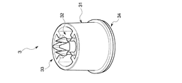
第3支持脚3は、図1に示すように、パネル本体PMの略中央部において、前記建築床面FLに接地しながら前記パネル本体PMを支持するものである。なお、図示はしていないが、当該第3支持脚3と建築床面FLとの間に、床面の高さ調節をするための高さ調節部材たる第3ライナー(図示せず)を設け、当該第3支持脚3が建築床面FLに対して直接接しないようにしてもよい。
As shown in FIG. 1, the
より具体的にこの第3支持脚3は、図12、図13などに示すように、概略円筒状をなす中央支持用周壁部31と、中央支持用周壁部31の内周に平面視略十字状に設けられ中央支持用周壁部31と略同じ高さ寸法を有する中央支持用リブ32と、中央支持用リブ32同士が交叉する部位に関連付けて設けられ中央支持用周壁部31の上端より上方に突出させてなる突起部たる中央支持用突起部33とを具備し、これら各部を合成樹脂により一体に形成した一体成形品である。
More specifically, as shown in FIGS. 12 and 13, the
さらに各部を詳述すると、中央支持用周壁部31は、第2支持脚2の隅部支持用周壁部21と略同様のものであるので説明を省略する。なお、本実施形態では、この中央支持用周壁部31の下端側に、建築床面FLに接地し得る円環状の中央支持用接地部34を設けている。
Further, each part will be described in detail. The central support
中央支持用リブ32は、前記第1脚本体11の第1リブ112と略同様のものであるので説明を省略する。
The
中央支持用突起部33は、裏材PM2の第4取付口T4に係合可能なものであり、その構成は、前記第1脚本体11の第1突起部113と略同様であるので説明を省略する。
The
なお、本実施形態では、図8等に示すように、高さ調節部材たる第1上ライナーR11および高さ調節部材たる第1下ライナーR12(以下、第1ライナーR1と総称する。)を、層状に重合配置可能に構成することにより、当該床パネルPが、前記建築床面FLの不陸に対応し得るものとなるようにしている。 In the present embodiment, as shown in FIG. 8 and the like, the first upper liner R11 as a height adjusting member and the first lower liner R12 as a height adjusting member (hereinafter collectively referred to as a first liner R1) are used. The floor panel P is configured to be able to cope with the unevenness of the building floor surface FL by being configured so as to be superposed in layers.
具体的には、第1上ライナーR11を、単独で前記第1支持脚1の下面側に取り付ける態様(第1取付態様)と、前記第1上ライナーR11と第1下ライナーR12とを重ねた状態で前記第1支持脚1の下面側に取り付ける態様(第2取付態様)とを取り得るようにしており、建築床面FLの不陸に対して適宜対応し得るようにしている。
Specifically, a mode (first mounting mode) in which the first upper liner R11 is independently attached to the lower surface side of the
各部を詳述すると、第1上ライナーR11は、概略薄板状の上ライナー面板部R111と、この上ライナー面板部R111の周端を略直角に起立させた上ライナー起立壁R112とを備えてなる。より具体的に、上ライナー面板部R111は、前記第1支持脚1の下面側を略覆い得る平面視略三角形状をなすものである。また、この上ライナー面板部R111の略中央部で且つ当該第1上ライナーR11と前記第1支持脚1とを取り付けた際にその第1支持脚1の第1挿入穴11Xと対応する位置に、円筒状の第1挿入部R11Xを設けている。
More specifically, the first upper liner R11 includes a substantially thin plate-like upper liner surface plate portion R111, and an upper liner standing wall R112 in which the peripheral end of the upper liner surface plate portion R111 is erected at a substantially right angle. . More specifically, the upper liner face plate portion R111 has a substantially triangular shape in plan view that can substantially cover the lower surface side of the
第1下ライナーR12は、概略薄板状の下ライナー面板部R121と、この下ライナー面板部R121の周端を略直角に起立させた下ライナー起立壁122とを備えてなる。より具体的に、下ライナー面板部R121は、前記第上ライナー面板部R111に重合配置してその下面側を略覆い得る平面視略三角形状をなすものである。また、この下ライナー面板部R121の略中央部で且つ当該第1下ライナーR12と前記第1上ライナーR11とを十合配置した際にその第1上ライナーR11の第1挿入部R11Xに挿入される円筒状の第2挿入部R12Xを設けている。そして、第1上ライナーR11と第1下ライナーR12とを重合配置した際に、上ライナー起立壁R112が下ライナー起立壁122に呑み込まれるように、下ライナー面板部R121を上ライナー面板部R111よりも若干大きく構成している
以上のように、本発明に係るスタッキング構造を実現可能な家具として開示した本実施形態に係る床パネルPは、前記第1支持脚に設けられ使用状態において退避するとともにスタッキング状態において突出する舌片部128と、前記突起129と係わり合う第1表材スリットSL1a(第1裏材スリットSL2a)とを具備しているので、上段に位置する床パネルPの突起129と、下段に位置する床パネルPの第1表材スリットSL1a (第1裏材スリットSL2a)とにより、前記床パネルP同士を上下方向にスタッキングさせた際に、前記舌片部128と前記第1表材スリットSL1a (第1裏材スリットSL2a)とにより床パネルP同士の水平方向への移動を規制する規制手段を構成することとなる。したがって、使用者はスタッキング作業及びスタッキング解除作業を簡易に行うことが出来るとともに、スタッキング状態にあるパネル同士の位置ずれの発生を抑制し安定した状態のままスタッキングを維持出来るスタッキング構造を実現できることとなる。
なお、第1表材スリットSL1aのみを被係合部たる穴部として機能させても良い。
The first lower liner R12 includes a substantially thin plate-like lower liner surface plate portion R121, and a lower
Note that only the first surface material slit SL1a may function as a hole serving as an engaged portion.
また、前記舌片部128を、合成樹脂からなる支持脚PS(第1支持脚1)に一体的に形成した概略薄板状のものとし、この舌片部128の先端部における下面には下方に向けて所定寸法突出させてなる突起129をも一体的に設けたので、簡素な構成で、舌片部128に付勢手段としての機能を付与することが出来、前記突起129に荷重受部としての機能を付与することが出来る。
Further, the
さらに、パネル本体PMをスチールからなるもので構成し、床面に置き敷しいた際の不陸に追従するために設けた分画開口部(前記第1表材スリットSL1a)を、前記突起129と係り合う穴部として利用しているので、前記支持脚と合わせて簡素な構成で規制手段を構成できる。すなわち、不陸に馴染む上に、収納安定性にも優れ、かつ剛性が高く歩行感の良い置敷タイプの床パネルPを提供できる。
Further, the panel body PM is made of steel, and a fractional opening (the first surface material slit SL1a) provided to follow the unevenness when placed on the floor is provided with the
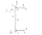
次に第2実施例について図20、21、22及び23を参照して説明する。
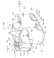
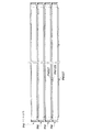
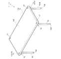
本発明に係るスタッキング構造を採用可能なテーブルTは、天板Taとこの天板Taを支持する複数本(本実施例では4本)の脚Tbとからなるもので、この脚Tbは、連結部Tcを介して天板Taの裏面Ta2側に折り畳み可能に支持されている。
Next, a second embodiment will be described with reference to FIGS.
The table T that can adopt the stacking structure according to the present invention is composed of a top plate Ta and a plurality of (four in this embodiment) legs Tb that support the top plate Ta. It is foldably supported on the back surface Ta2 side of the top plate Ta via the portion Tc.
天板Taは矩形状を成す板材からなるもので、その表面Ta1には後述する係合片KT2の対応位置(本実施例では天板の4隅)に被係合部たる凹部U1を設けている。 The top plate Ta is made of a rectangular plate material, and the surface Ta1 is provided with recesses U1 that are engaged portions at corresponding positions (four corners of the top plate in this embodiment) of an engagement piece KT2 described later. Yes.
脚Tbは、スチール等の角柱で構成されるもので、上端部を連結部Tcに軸部Tb1を介して回動可能に連結されており、下端部を床面に設置する接地部Tb2としている。なお、脚Tbの上端部における側面には、後述する荷重受部に外力を付与し得る凸部Tb3が設けられる。 The leg Tb is composed of a prism such as steel, and the upper end portion is rotatably connected to the connecting portion Tc via the shaft portion Tb1, and the lower end portion is a grounding portion Tb2 installed on the floor surface. . In addition, the convex part Tb3 which can provide external force to the load receiving part mentioned later is provided in the side surface in the upper end part of leg Tb.
連結部Tcは、下方に向けて開口するブロック状のもので上壁Tc1を天板Taの裏面4隅に適宜の手段(ビス等)にて取り付けられている。また、連結部Tcの開口内TTには、前記脚Tbを回動可能に支持する軸部Tb1と、係合部KTが設けられている。しかして、脚Tbは軸部Tb1を中心として天板Taの長手方向に向けて天板Taの裏面Ta2に脚Tbの設置部Tb2を近接させるように折り畳むことが出来る。 The connecting portion Tc is a block-like opening that opens downward, and the upper wall Tc1 is attached to the four corners of the back surface of the top plate Ta by appropriate means (such as screws). A shaft portion Tb1 that rotatably supports the leg Tb and an engaging portion KT are provided in the opening TT of the connecting portion Tc. Thus, the leg Tb can be folded so that the installation portion Tb2 of the leg Tb is close to the back surface Ta2 of the top plate Ta toward the longitudinal direction of the top plate Ta with the shaft portion Tb1 as the center.
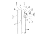
係合部KTは、前記連結部Tcの下面Tc2から突出する突出位置(図22における実線部分参照)と下面Tc2から突出しない退避位置(開口TT内の位置)を取り得るものであって、基端側を前記軸部Tb1より外方側における位置に支持される基端部KT1と、被係合部と係り合う爪状の係合片KT2と、前記凸部Tb3による外力を受ける荷重受部KT3とからなる。本実施例では、係合部KTを、正面視略直角三角形を成す板状のものとし、頂点側を基端部KT1、直角側の一部を外方に延出させた箇所を荷重受部KT3、残る角側を係合片KT2としている。なお、係合部K(係合片KT2)は開口TT内に設けられた図示しない付勢手段(合成樹脂による弾性、バネによる弾性等)にて退避位置(図22における二点鎖線部分参照)から突出位置(図22における実線部分参照)へと付勢するようにしている。 The engaging portion KT can take a protruding position (see a solid line portion in FIG. 22) protruding from the lower surface Tc2 of the connecting portion Tc and a retracted position (position in the opening TT) not protruding from the lower surface Tc2. A base end portion KT1 whose end side is supported at a position on the outer side from the shaft portion Tb1, a claw-like engagement piece KT2 that engages with the engaged portion, and a load receiving portion that receives an external force by the convex portion Tb3 It consists of KT3. In this embodiment, the engaging portion KT is a plate-like shape that forms a substantially right-angled triangle when viewed from the front, the apex side is the base end portion KT1, and the portion where the right-angle side part extends outward is the load receiving portion. KT3, and the remaining corner side is an engagement piece KT2. The engagement portion K (engagement piece KT2) is retracted by an urging means (not shown) provided in the opening TT (elasticity by synthetic resin, elasticity by spring, etc.) (see the two-dot chain line portion in FIG. 22). It is urged | biased to a protrusion position (refer the continuous line part in FIG. 22).
ここで、テーブルTをスタッキングさせる場合の動作について図22および図23を参照して説明する。 Here, the operation when stacking the table T will be described with reference to FIGS.
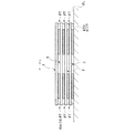
まず、使用状態においては、前記脚Tbの上端部の側面位置に設けた凸部Tb3と、前記荷重受部KT3とが当設している。すなわち、付勢手段による弾性力に抗して凸部Tb3が荷重受部KT3に作用することにより係合片KT2を退避位置に位置付けている。(図22における二点鎖線部分参照)次に、この状態から、脚Tbを折り畳んで行くと脚Tbの回動に伴い凸部Tb3の位置も変位していくので、係合片KT2は付勢手段の弾性力により連結部Tcの下面Tc2から突出することになる。したがって、脚Tbを折り畳んだ状態においては、荷重受部KT3が外力を受けない為、付勢手段の働きにより係合片KT2が突出位置をとることとなる。(図22における実線部分参照)他の脚Tbにおいても同様にして全ての脚Tbを折り畳み、これら平板状を成す折り畳まれた複数のテーブルTbを鉛直方向に積重ねていけば良い。この時、天板Taの表面Ta1に設けた穴部U1と係合片KT2が係わり合うことで水平方向の位置ズレが防止できることとなる。なお、最下段に位置するテーブルTの係合片KT2は床面FLに押圧されることとなるので、退避位置に位置することとなる。(図23参照)
テーブルTを使用状態にするには、脚Tbが垂直になるように回動させれば良く、この回動動作にともなって、凸部Tb3が荷重受部KT3に当設し、係合片KT2を押し上げるようにして退避位置へと位置付ける。すなわちこの状態では、係合片KT2は開口TT内に位置し、連結部Tcの下面Tc2より突出しないこととなる。(図22における二点鎖線部分参照)
続いて、第3実施例について図24、25及び26を参照して説明する。
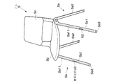
このイスSは、左右一対に設けられ側面視ハの字型を成す脚Sa、Saと、この脚Sa、Sa間に設けられる座Sbと、この座Sbの後部から上方に連続して設けられる背Scとからなるもので、鉛直方向にスタッキング可能なものであり、脚Sa、Sa間に規制手段FSを設けている。
First, in a use state, the convex portion Tb3 provided at the side surface position of the upper end portion of the leg Tb and the load receiving portion KT3 are provided. That is, the protrusion Tb3 acts on the load receiving portion KT3 against the elastic force of the urging means, thereby positioning the engagement piece KT2 at the retracted position. (Refer to the alternate long and two short dashes line portion in FIG. 22) Next, when the leg Tb is folded from this state, the position of the convex portion Tb3 is also displaced as the leg Tb rotates, so that the engaging piece KT2 is energized. It protrudes from the lower surface Tc2 of the connecting portion Tc by the elastic force of the means. Therefore, in the state where the leg Tb is folded, the load receiving portion KT3 does not receive an external force, so that the engaging piece KT2 takes the protruding position by the action of the urging means. (See the solid line portion in FIG. 22) For the other legs Tb, all the legs Tb may be folded in the same manner, and a plurality of folded tables Tb having a flat plate shape may be stacked in the vertical direction. At this time, since the hole U1 provided on the surface Ta1 of the top plate Ta and the engagement piece KT2 are engaged with each other, the horizontal displacement can be prevented. Note that the engagement piece KT2 of the table T positioned at the lowermost stage is pressed against the floor surface FL, and thus is positioned at the retracted position. (See Figure 23)
In order to put the table T into use, the leg Tb may be rotated so that it is vertical. With this rotation, the convex portion Tb3 contacts the load receiving portion KT3, and the engagement piece KT2 Push up to position to the retracted position. That is, in this state, the engagement piece KT2 is located in the opening TT and does not protrude from the lower surface Tc2 of the connecting portion Tc. (Refer to the two-dot chain line portion in FIG. 22)
Next, a third embodiment will be described with reference to FIGS.
The chairs S are provided in a pair of left and right legs Sa and Sa having a C-shape in side view, a seat Sb provided between the legs Sa and Sa, and a seat Sb provided continuously from the rear part. It consists of a back Sc and can be stacked in the vertical direction, and a regulating means FS is provided between the legs Sa and Sa.
詳述すると、脚Saの前脚Sa1の前向き面Sa11に被取付部U2、同後向き面Sa12側に係合部KSを設けている。係合部KSは、脚Saの下端に取り付けられる設置部材Sa3を利用して設けられており、前脚Sa1の後向き面Sa12から突出する位置(図25における実線及び二点鎖線部分参照)と、前脚Sa1の内部SSに収容される退避位置(図25における破線部分参照)とに変位可能である。より具体的に本実施例にかかる係合部KSは、略矩形状をなすものであり、下方に位置する一方の角部を基端部KS1とし、この角部KS1の対角上に位置する角部を係合片KS2としている。なお、係合片KS2は、その自重により常時退避位置から突出位置へ付勢されている。また、下方に位置する他方の角部を荷重受部KS3としており、イスSを床面FLに接地させない状態では、係合片KS2が後向き面Sa12から後方に向けて突出するよう、また荷重受部KS3を設置部下面Sa31から下方に向けて突出するように設定している。(図25における破線部分参照)したがって、イスSを床面上FLに配置させた使用状態においては、イスSの自重を荷重受部KS3が受けることとなり係合片KS2を突出位置から退避位置へ変位させることとなる。被係合部U2は図24および図26に示すように複数のイスSをスタッキングさせた際に、上位に位置するイスSの係合片KS2に対応する箇所(前脚Sa1の前向き面Sa11所定箇所)に長穴U2を設けることで構成される。 Specifically, the attachment portion U2 is provided on the front facing surface Sa11 of the front leg Sa1 of the leg Sa, and the engaging portion KS is provided on the rear facing surface Sa12 side. The engaging portion KS is provided by using an installation member Sa3 attached to the lower end of the leg Sa, a position protruding from the rearward surface Sa12 of the front leg Sa1 (see the solid line and the two-dot chain line portion in FIG. 25), the front leg It can be displaced to the retracted position (see the broken line portion in FIG. 25) accommodated in the internal SS of Sa1. More specifically, the engaging portion KS according to the present embodiment has a substantially rectangular shape, and has one corner portion positioned below as a base end portion KS1 and is positioned on a diagonal of the corner portion KS1. The corner portion is an engagement piece KS2. The engagement piece KS2 is always urged from the retracted position to the protruding position by its own weight. In addition, the other corner portion located below is a load receiving portion KS3, and in a state where the chair S is not grounded to the floor surface FL, the engagement piece KS2 protrudes rearward from the rear surface Sa12, and the load receiving portion KS3. The part KS3 is set so as to protrude downward from the installation part lower surface Sa31. (Refer to the broken line portion in FIG. 25) Therefore, in a use state in which the chair S is disposed on the floor surface FL, the load receiving portion KS3 receives the weight of the chair S and the engagement piece KS2 is moved from the protruding position to the retracted position. It will be displaced. 24 and 26, when the plurality of chairs S are stacked, the engaged portion U2 corresponds to a portion corresponding to the engagement piece KS2 of the chair S positioned at a higher position (a predetermined portion on the front facing surface Sa11 of the front leg Sa1). ) Is provided with a long hole U2.
したがって、本実施例においては、イスSを床面FLから持ち上げると係合部KSの自重により係合片KS2が後向き面Sa12より突出するので、上方に積重ねる際には下位のイスSに設けた長穴U2と上位の係合片KS2が係り合うので位置ずれを防止できる。特に、脚Saの下端側に係合部KSを設けているので、スタッキング状態において不意の外力を受け易い脚部Saを安定的に保持することにより良好なスタッキングが維持出来る。なお、係合部KSは第2実施例と同様に樹脂、バネの弾性を利用して付勢手段を構成しても良い。さらに、後脚Sa2において規制手段FSを設けても良い。 Therefore, in this embodiment, when the chair S is lifted from the floor surface FL, the engaging piece KS2 protrudes from the rear surface Sa12 due to the weight of the engaging portion KS. Since the elongated hole U2 and the upper engagement piece KS2 are engaged with each other, the displacement can be prevented. In particular, since the engaging portion KS is provided on the lower end side of the leg Sa, good stacking can be maintained by stably holding the leg portion Sa that is susceptible to unexpected external force in the stacking state. In addition, the engaging part KS may constitute the urging means using the elasticity of the resin and the spring as in the second embodiment. Further, a regulating means FS may be provided in the rear leg Sa2.
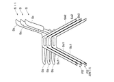
さらに、第4実施例について図27、28及び29を参照して説明する。
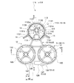
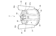
この折り畳みイスSSは中空状の丸パイプによってフレーム(前脚及び後脚)を構成し、特開平9−65949号公報に開示されるスライドリンク機構SRを採用したものであって、上部に背SScを備えた下向きUの字型を成す前脚SSa1と、この前脚SSa1の適宜箇所にスライドリンク機構SRを介して連結された上向きUの字型を成す後脚SSa2と、これら両脚SSa1、SSa2に回動可能に支持される座SSbとを具備するものである。各部の具体的な説明は特開平9−65949号公報と同じ為に省略するが、本実施例においては、係合部KSSをスライドリンク機構SRの一部に設け、被係合部U3を前脚SSa1の対応個所に設けることで、規制手段FSSを構成している。
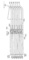
スライドリンク機構SRを構成するスライドリンク本体SRM(図28参照)は、上端部に前脚に回動可能に連結される回転部SRM1を設け、下端部に後脚SSa2内に挿抜可能に挿入される挿入部SRM2を設けてなるものであり、挿入部SRM2の後向き面SRM21から係合部KSSを突没可能に設けている。係合部KSSは、三角形を成す板状のもので、下端を挿入部内に回動可能に支持される基端部KSS1とし、下端から後向き上方に延びるように傾斜面KSS3を有する係合片KSS2としている。なお、係合片KSSは他の実施例と同様に適宜の付勢手段により後向きに突出するように常時付勢されている。折り畳んだ状態(図28(b)及び図29参照)では、挿入部SRM2が露出しており係合片KSS2が突出位置に位置する。この折り畳み状態から使用状態(図27及び図28(a)参照)へ可変させると、この可変動作に伴い挿入部SRM2が後脚SSa2内に挿入されていく。この時、後脚SSa2の開口縁SSa21と係合片KSS2の傾斜面KSS3が当設することで係合片KSS2は挿入部SRM2の内部へ位置付けられるようになる。すなわち、係合片KSSの傾斜面KSS3が、開口縁SSa21から外力を受けることにより退避位置(挿入部内SSS)へと変位させる荷重受部KSS3として機能することとなる。
Further, the fourth embodiment will be described with reference to FIGS.
This folding chair SS has a frame (front legs and rear legs) made of hollow round pipes and adopts a slide link mechanism SR disclosed in Japanese Patent Laid-Open No. 9-65949, and has a back SSc on the top. A front leg SSa1 having a downward U-shape provided, a rear leg SSa2 having an upward U-shape connected to an appropriate portion of the front leg SSa1 via a slide link mechanism SR, and turning to both the legs SSa1 and SSa2 And a seat SSb supported in a possible manner. Although a detailed description of each part is omitted because it is the same as that of JP-A-9-65949, in this embodiment, the engaging part KSS is provided in a part of the slide link mechanism SR, and the engaged part U3 is the front leg. By providing the corresponding portion of SSa1, the regulating means FSS is configured.
The slide link main body SRM (see FIG. 28) constituting the slide link mechanism SR is provided with a rotating portion SRM1 that is rotatably connected to the front leg at the upper end portion, and is inserted into the rear leg SSa2 at the lower end portion so as to be insertable / removable. The insertion portion SRM2 is provided, and the engagement portion KSS is provided so as to be able to project and retract from the rear surface SRM21 of the insertion portion SRM2. The engaging portion KSS is a triangular plate-shaped member, and a lower end is a base end portion KSS1 that is rotatably supported in the insertion portion, and an engaging piece KSS2 having an inclined surface KSS3 so as to extend rearward and upward from the lower end. It is said. Note that the engagement piece KSS is always urged so as to protrude rearward by appropriate urging means as in the other embodiments. In the folded state (see FIG. 28B and FIG. 29), the insertion portion SRM2 is exposed, and the engagement piece KSS2 is located at the protruding position. When the folding state is changed to the use state (see FIGS. 27 and 28A), the insertion portion SRM2 is inserted into the rear leg SSa2 along with the changing operation. At this time, when the opening edge SSa21 of the rear leg SSa2 and the inclined surface KSS3 of the engagement piece KSS2 are disposed, the engagement piece KSS2 is positioned inside the insertion portion SRM2. That is, the inclined surface KSS3 of the engagement piece KSS functions as the load receiving portion KSS3 that is displaced to the retracted position (inside the insertion portion SSS) by receiving an external force from the opening edge SSa21.
スタッキングする際には、図29に示すように下位の係合部KSSに上位の被係合部U3を係り合うようにすれば良い。 When stacking, as shown in FIG. 29, the upper engaged portion U3 may be engaged with the lower engaging portion KSS.
本実施例のような折り畳みイスにおいては、脚側に規制手段FSSを設けているので、スタッキング状態を維持出来るとともに背の設計自由度が増すので、使用時及び不使用時の双方において優れたものが提供できる。 In the folding chair as in this embodiment, since the regulating means FSS is provided on the leg side, the stacking state can be maintained and the design freedom of the back is increased, so that it is excellent both in use and not in use. Can be provided.
その他、各部の具体的構成についても上記実施形態に限られるものではなく、本発明の趣旨を逸脱しない範囲で種々変形が可能である。 In addition, the specific configuration of each part is not limited to the above embodiment, and various modifications can be made without departing from the spirit of the present invention.
K、KT、KS、KSS・・・・・・係合部
U、U1、U2、U3・・・・・・被係合部
F、FT、FS、FSS・・・・・規制手段
128、KT2、KS2、KSS2・・・・係合片
129、KT3、KS3、KSS3・・・・・荷重受部
P・・・・・家具(床パネル)
T・・・・家具(テーブル)
S・・・・家具(イス)
SS・・・・家具(折り畳みイス)
K, KT, KS, KSS ·········· Engagement portion U, U1, U2, U3 ····························· , KS2, KSS2, ...
T ... Furniture (table)
S ... Furniture (chair)
SS ··· Furniture (folding chair)
Claims (8)
第1の家具が、少なくとも所定位置に設けられ使用状態において退避するとともにスタッキング状態において突出する係合部を具備してなり、
第2の家具が、少なくとも前記係合部と係わり合う被係合部を具備してなり、
前記第1の家具と前記第2の家具とを所定方向にスタッキングさせた際に、前記係合部と前記被係合部とにより前記所定方向とは異なる方向への移動を規制する規制手段を構成することを特徴とする家具のスタッキング構造。 A structure for stacking a plurality of furniture,
The first furniture comprises an engaging portion that is provided at least in a predetermined position and retracts in a use state and protrudes in a stacking state,
The second furniture comprises at least an engaged portion that engages with the engaging portion,
Restricting means for restricting movement in a direction different from the predetermined direction by the engaging portion and the engaged portion when the first furniture and the second furniture are stacked in a predetermined direction. Furniture stacking structure characterized by comprising.
Priority Applications (1)
| Application Number | Priority Date | Filing Date | Title |
|---|---|---|---|
| JP2004107938A JP2005290861A (en) | 2004-03-31 | 2004-03-31 | Fitment stacking structure and stackable fitment |
Applications Claiming Priority (1)
| Application Number | Priority Date | Filing Date | Title |
|---|---|---|---|
| JP2004107938A JP2005290861A (en) | 2004-03-31 | 2004-03-31 | Fitment stacking structure and stackable fitment |
Publications (1)
| Publication Number | Publication Date |
|---|---|
| JP2005290861A true JP2005290861A (en) | 2005-10-20 |
Family
ID=35324107
Family Applications (1)
| Application Number | Title | Priority Date | Filing Date |
|---|---|---|---|
| JP2004107938A Pending JP2005290861A (en) | 2004-03-31 | 2004-03-31 | Fitment stacking structure and stackable fitment |
Country Status (1)
| Country | Link |
|---|---|
| JP (1) | JP2005290861A (en) |
-
2004
- 2004-03-31 JP JP2004107938A patent/JP2005290861A/en active Pending
Similar Documents
| Publication | Publication Date | Title |
|---|---|---|
| CN102897060B (en) | The pivoting device of seat | |
| CA2151605C (en) | Combined chair | |
| US20150201759A1 (en) | Chair | |
| US9713382B2 (en) | Chair with extendable and retractable ganging system | |
| US8152237B2 (en) | Stacking chair | |
| US9351577B2 (en) | Chair with cushion and stackable configuration | |
| KR101101187B1 (en) | Furniture with folding support | |
| JP2005290861A (en) | Fitment stacking structure and stackable fitment | |
| JP2019063177A (en) | Chair | |
| JP6796522B2 (en) | Ready-to-assemble furniture | |
| KR200475666Y1 (en) | A sectional chair | |
| JP2011024858A (en) | Multi-functional chair | |
| JP5890660B2 (en) | Chair | |
| JP4785240B2 (en) | Folding chair | |
| JP2005290875A (en) | Floor panel | |
| KR200427977Y1 (en) | Prefab chair | |
| US20250338956A1 (en) | Furniture module and a method of assembling a furniture module | |
| KR102720725B1 (en) | The structure combinating the mesh net of the chair seat | |
| KR20130053719A (en) | Multifunctional chair | |
| JP6192219B2 (en) | Chair | |
| JP2005319149A (en) | Furniture | |
| JP2018057731A (en) | Furniture side table | |
| JP7117202B2 (en) | Chair | |
| JP2791221B2 (en) | Combination chair | |
| HK40105445A (en) | Compliant backrest |
Legal Events
| Date | Code | Title | Description |
|---|---|---|---|
| A621 | Written request for application examination |
Effective date: 20060117 Free format text: JAPANESE INTERMEDIATE CODE: A621 |
|
| A977 | Report on retrieval |
Effective date: 20071225 Free format text: JAPANESE INTERMEDIATE CODE: A971007 |
|
| A131 | Notification of reasons for refusal |
Free format text: JAPANESE INTERMEDIATE CODE: A131 Effective date: 20081216 |
|
| A02 | Decision of refusal |
Free format text: JAPANESE INTERMEDIATE CODE: A02 Effective date: 20090407 |