JP2005290844A - Sleeper tree, sleeper tree manufacturing method and sleeper tree repair method - Google Patents
Sleeper tree, sleeper tree manufacturing method and sleeper tree repair method Download PDFInfo
- Publication number
- JP2005290844A JP2005290844A JP2004107561A JP2004107561A JP2005290844A JP 2005290844 A JP2005290844 A JP 2005290844A JP 2004107561 A JP2004107561 A JP 2004107561A JP 2004107561 A JP2004107561 A JP 2004107561A JP 2005290844 A JP2005290844 A JP 2005290844A
- Authority
- JP
- Japan
- Prior art keywords
- cylindrical body
- sleeper
- hole
- main body
- female screw
- Prior art date
- Legal status (The legal status is an assumption and is not a legal conclusion. Google has not performed a legal analysis and makes no representation as to the accuracy of the status listed.)
- Pending
Links
Images


Landscapes
- Machines For Laying And Maintaining Railways (AREA)
Abstract
【課題】 本体部10に雌ねじ部27を有する筒状体11を埋設し、ボルト92により
まくら木1にタイプレートなどを固定することができるまくら木1において、雌ねじ部2
7の位置や傾きを精度良く形成することができるものを提供する。
【解決手段】 筒状体11の外側には、所定のピッチで螺旋状に形成された係止部26
が設けられており、本体部10の貫通孔17には係止部26に対応する螺旋部が設けられ
ている。そして、本体部10と筒状体11とを螺合する。
【選択図】 図4PROBLEM TO BE SOLVED: To provide a female screw part 2 in a sleeper 1 in which a cylindrical body 11 having a female screw part 27 is embedded in a main body part 10 and a tie plate or the like can be fixed to the sleeper 1 by a bolt 92.
7 capable of accurately forming the position and inclination of 7 is provided.
SOLUTION: On the outside of a cylindrical body 11, a locking portion 26 formed in a spiral shape with a predetermined pitch is provided.
A spiral portion corresponding to the locking portion 26 is provided in the through hole 17 of the main body portion 10. And the main-body part 10 and the cylindrical body 11 are screwed together.
[Selection] Figure 4
Description
本発明は、鉄道軌道などに用いられるまくら木に関するものである。 The present invention relates to sleepers used for railway tracks and the like.
従来より、レールを敷設するためにまくら木が用いられている。そして、レールをまく
ら木に固定するため、固定金具が用いられている。
固定金具は、まくら木に直接固定されたり、タイプレートに固定される。また、タイプ
レートにレールに対して垂直方向の位置を変えるために傾斜溝が設けられて、固定金具の
位置を変更可能にする場合もある。
Conventionally, sleepers have been used to lay rails. A fixing bracket is used to fix the rail to the sleeper.
The fixing bracket is fixed directly to the sleeper or fixed to the tie plate. In some cases, the tie plate is provided with an inclined groove to change the position in the direction perpendicular to the rail, so that the position of the fixture can be changed.
そして、タイプレートや固定金具をまくら木に固定するために、まくら木側に雌ねじを
設け、タイプレートや固定金具に貫通孔を設け、貫通孔にボルトを通して、まくら木の雌
ねじと締結する方法がある。
In order to fix the tie plate and the fixing bracket to the sleeper, there is a method in which a female screw is provided on the sleeper side, a through hole is provided in the tie plate or the fixing bracket, and a bolt is passed through the through hole to fasten with the female screw of the sleeper.
このまくら木側の雌ねじは、まくら木本体に穴を設け、この穴に雌ねじが設けられた筒
状体を挿入して固定するために設けている。このような方法は、長繊維で補強された硬質
樹脂発泡体などにより形成されたまくら木に良く用いられている。
この技術に関連するまくら木として、特許文献1に記載されるようなまくら木などがあ
る。
As a sleeper tree related to this technique, there is a sleeper tree described in
特許文献1に開示されたまくら木は、ねじ部への横圧力及びふく進力に対する強度が上
がり、引き抜き抵抗力が大きく、確実にタイプレートを止めることができる。
The sleeper disclosed in
しかしながら、特許文献1などに開示されたまくら木では、筒状体を本体部の穴に挿入
した後に、筒状体のずれを防止しながら固定するので本体部の穴と筒状体との間に接着剤
が充填される。そして、この接着剤の充填のため、本体部の穴の内径は筒状体の外径より
も大きくしてあり、挿入後、本体部の穴と筒状体との間には一定の隙間ができる。したが
って、本体部の穴と筒状体とを精度良く形成しても、接着剤が硬化するまでにずれたり、
傾いたりするおそれがあり、雌ねじの位置の精度を安定的に高めるには限界があった。ま
た、接着剤が硬化するまで、筒状体が移動しないように注意して製作する必要があり、大
変手間がかかっていた。
However, in the sleeper disclosed in
There is a risk of tilting, and there is a limit to stably increasing the accuracy of the position of the female screw. In addition, it is necessary to manufacture the cylindrical body with care so that the cylindrical body does not move until the adhesive is cured, which is very troublesome.
そこで、本発明は、雌ねじの位置や傾きを精度良く形成することができるまくら木を提
供することを課題とするものである。
Then, this invention makes it a subject to provide the sleeper which can form the position and inclination of a female screw with sufficient precision.
そして、上記した目的を達成するための請求項1に記載の発明は、貫通孔が設けられた
本体部と、内部に雌ねじが設けられた筒状体と、前記筒状体と連結する座金を有し、前記
筒状体は貫通孔に配置されて隙間に接着剤を充填し、本体部の下側に座金を配置して筒状
体の上方への抜け防止を行いながら筒状体と本体部とを固定し、筒状体の雌ねじを用いて
締結装置との締結を行うことができるまくら木において、前記筒状体は雌ねじの軸を中心
軸とする円柱状であって、所定のピッチで螺旋状に形成された係止部が設けられており、
本体部の貫通孔には前記係止部に対応する螺旋部が設けられて本体部と筒状体とを螺合し
ていることを特徴とするまくら木である。
ここで、貫通孔の螺旋部は筒状体の係止部に対応しているが、この例として、一方が凸
状であり他方が凹状であり、これらの断面形状が同様なものである。また、凸状側の断面
形状は、全域に同じであっても良く、部分的に異なっていても良い。
The invention described in
The sleeper is characterized in that a spiral portion corresponding to the locking portion is provided in the through hole of the main body portion, and the main body portion and the cylindrical body are screwed together.
Here, although the spiral portion of the through hole corresponds to the locking portion of the cylindrical body, as an example, one is convex and the other is concave, and the cross-sectional shapes thereof are the same. Further, the cross-sectional shape on the convex side may be the same throughout the region, or may be partially different.
請求項1に記載の発明によれば、雌ねじの軸を中心軸とする円柱状であり、所定のピッ
チで凸状又は凹状に螺旋状に形成された係止部が設けられている筒状体を、前記係合部に
対応する凹状又は凸状の螺旋部が設けられている本体部の貫通孔に挿入して、本体部と筒
状体とを螺合しているので、位置ずれなく、精度良く挿入することができる。
According to the first aspect of the present invention, the cylindrical body has a cylindrical shape with the axis of the female screw as the central axis, and is provided with a locking portion that is helically formed in a convex shape or a concave shape at a predetermined pitch. Is inserted into the through hole of the main body portion provided with a concave or convex spiral portion corresponding to the engaging portion, and the main body portion and the cylindrical body are screwed together, so that there is no displacement. It can be inserted with high accuracy.
請求項2に記載の発明は、筒状体の係止部又は貫通孔の螺旋部は凸状であって断面形状
に不連続な部分が設けられていることを特徴とする請求項1に記載のまくら木である。
The invention according to
請求項2に記載の発明によれば、筒状体の係止部又は貫通孔の螺旋部は凸状であって断
面形状に不連続な部分が設けられているので、筒状体と貫通孔に設けられる接着剤が不連
続部に浸入してより回転を阻止して確実に固定することができる。
According to the second aspect of the present invention, since the locking portion of the cylindrical body or the spiral portion of the through hole is convex and the discontinuous portion is provided in the cross-sectional shape, the cylindrical body and the through hole are provided. It is possible to prevent the rotation of the adhesive provided on the discontinuous portion and prevent the rotation, thereby securing the discontinuity.
請求項3に記載の発明は、本体部の上側で筒状体と連結する上板が設けられ、前記上板
と座金によって本体部を挟んでいることを特徴とする請求項1又は2に記載のまくら木で
ある。
According to a third aspect of the present invention, an upper plate connected to the cylindrical body is provided on the upper side of the main body, and the main body is sandwiched between the upper plate and a washer. This is a sleeper tree.
請求項3に記載の発明によれば、上板と座金によって本体部を挟んでいるので、さらに
筒状体の固定を確実にすることができる。
According to the third aspect of the present invention, since the main body is sandwiched between the upper plate and the washer, the fixing of the cylindrical body can be further ensured.
請求項4に記載の発明は、雌ねじ部の上端側には、雌ねじ部の内径よりも大きい角穴部
が設けられていることを特徴とする請求項1〜3いずれかに記載のまくら木である。
The invention according to claim 4 is the sleeper according to any one of
請求項4に記載の発明によれば、雌ねじ部の上端側には、雌ねじ部の内径よりも大きい
角穴部が設けられているので、角穴部に所定の工具を挿入することにより、挿入作業や取
り外し作業が行いやすい。
According to the invention described in claim 4, since the square hole portion larger than the inner diameter of the female screw portion is provided on the upper end side of the female screw portion, the insertion can be performed by inserting a predetermined tool into the square hole portion. Easy to work and remove.
筒状体は金属によって構成されていてもよく(請求項5)、また、樹脂製であっても良
い(請求項6)。
The cylindrical body may be made of metal (Claim 5) or may be made of resin (Claim 6).
また、本体部は、ガラス長繊維強化硬質合成樹脂発泡体によって構成されていてもよい
(請求項7)。
Moreover, the main-body part may be comprised with the glass long fiber reinforced hard synthetic resin foam (Claim 7).
請求項8に記載の発明は、請求項4〜7のいずれかのまくら木を製造するまくら木の製
造方法であって、操作部と、角穴部に対応する形状である挿入部とを有する着脱工具を用
い、挿入部を角穴部に挿入しながら操作部を回転させて筒状体の挿入する工程を有する特
徴とするまくら木の製造方法である。
ここで、角穴部に対応する形状である挿入部とは、角穴部に挿入可能であり、挿入部を
角穴部に挿入した状態で、挿入部の回転を角穴部側に伝達できればどのような形状でも良
い。
The invention according to claim 8 is a method for manufacturing a sleeper according to any one of claims 4 to 7, wherein the removable tool has an operation part and an insertion part having a shape corresponding to the square hole part. This is a method for manufacturing a sleeper having a step of inserting a cylindrical body by rotating an operation portion while inserting an insertion portion into a square hole portion.
Here, the insertion part having a shape corresponding to the square hole part can be inserted into the square hole part, and the rotation of the insertion part can be transmitted to the square hole part side with the insertion part inserted into the square hole part. Any shape is acceptable.
請求項8に記載の発明によれば、操作部と挿入部とを有する着脱工具を用いて、挿入部
を角穴部に挿入しながら操作部を回転させて筒状体の挿入するので筒状体の挿入が行いや
すい。
According to the eighth aspect of the present invention, the cylindrical body is inserted by rotating the operation portion while inserting the insertion portion into the square hole portion using the detachable tool having the operation portion and the insertion portion. Easy to insert the body.
請求項9に記載の発明は、前記着脱工具の挿入部と操作部の間には鍔部が設けられ、筒
状体を挿入する工程において、前記鍔部がまくら木の本体部に接触するまで行うものであ
ることを特徴とする請求項8に記載のまくら木の製造方法である。
According to a ninth aspect of the present invention, a hook is provided between the insertion portion and the operation portion of the detachable tool, and the step is performed until the hook contacts the main body of the sleeper in the step of inserting the cylindrical body. It is a thing, It is a thing, The manufacturing method of the sleeper tree of Claim 8.
請求項9に記載の発明によれば、着脱工具の挿入部と操作部の間には鍔部が設けられ、
鍔部がまくら木の本体部に接触するまで筒状体を挿入するので、本体部の面と合致するよ
うに挿入が可能である。
According to invention of Claim 9, a collar part is provided between the insertion part and operation part of a detachable tool,
Since the cylindrical body is inserted until the collar portion comes into contact with the main body of the sleeper, it can be inserted so as to match the surface of the main body.
請求項10に記載の発明は、請求項4〜7のいずれかのまくら木を補修するまくら木の
補修方法であって、操作部と、角穴部に対応する形状である挿入部とを有する着脱工具を
用い、挿入部を角穴部に挿入しながら操作部を回転させて筒状体を貫通孔から取り出す工
程を有することを特徴とするまくら木の補修方法である。
A tenth aspect of the present invention is a sleeper repairing method for repairing the sleeper according to any one of the fourth to seventh aspects, wherein the removable tool has an operation portion and an insertion portion having a shape corresponding to the square hole portion. A method of repairing a sleeper, comprising the step of rotating the operating portion while inserting the insertion portion into the square hole portion and taking out the cylindrical body from the through hole.
請求項10に記載の発明によれば、操作部と挿入部とを有する着脱工具を用いて、挿入
部を角穴部に挿入しながら操作部を回転させて筒状体の取り外しを行うので筒状体の取り
外しが行いやすい。
According to the tenth aspect of the present invention, the cylindrical body is removed by rotating the operation portion while inserting the insertion portion into the square hole portion by using a detachable tool having the operation portion and the insertion portion. Easy to remove.
本発明によれば、雌ねじの位置や傾きを精度良く形成することができる。 According to the present invention, the position and inclination of the female screw can be formed with high accuracy.
以下さらに本発明の具体的実施例について説明する。図1は、本発明の第1の実施形態
のまくら木にレールを取り付けた状態の正面図である。図2は、本発明の第1の実施形態
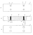
のまくら木の天面図である。図3は、本発明の第1の実施形態のまくら木の3面図であり
、(a)は天面図、(b)は一部を切り欠いた状態の正面図、(c)は底面図である。図
4は、図3(b)の筒状体付近を拡大し、ボルトを示した正面図である。図5は、図3(
b)の筒状体付近を拡大した図であって、筒状体を挿入する前を示した正面図である。図
6〜9は、筒状体の変形例を示した正面図及び底面図である。図10は、筒状体の変形例
と着脱工具を示した正面図である。図11は、本発明の第2の実施形態のまくら木の筒状
体付近を拡大した正面図である。図12は本発明の変形例を示す断面図であって、(a)
は筒状体を挿入する前の図、(b)は筒状体を挿入した状態の図である。
Hereinafter, specific examples of the present invention will be described. FIG. 1 is a front view of a state in which a rail is attached to a sleeper according to a first embodiment of the present invention. FIG. 2 is a top view of the sleeper tree according to the first embodiment of the present invention. 3A and 3B are three views of the sleeper according to the first embodiment of the present invention, in which FIG. 3A is a top view, FIG. 3B is a front view with a part cut away, and FIG. 3C is a bottom view. It is. FIG. 4 is an enlarged front view of the vicinity of the cylindrical body of FIG. FIG. 5 shows FIG.
It is the figure which expanded the cylindrical body vicinity of b), Comprising: It is the front view which showed before inserting a cylindrical body. 6 to 9 are a front view and a bottom view showing modified examples of the cylindrical body. FIG. 10 is a front view showing a modification of the cylindrical body and a detachable tool. FIG. 11 is an enlarged front view of the vicinity of the cylindrical body of the sleeper tree according to the second embodiment of the present invention. FIG. 12 is a cross-sectional view showing a modification of the present invention.
Fig. 5 is a view before inserting the cylindrical body, and Fig. 5B is a view showing a state where the cylindrical body is inserted.
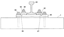
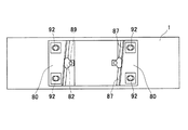
本発明の第1の実施形態におけるまくら木1は図1〜図3に示されており、通常のもの
と同様に角柱状である。そして、図1に示されるように、まくら木1の上側にタイプレー
ト80と固定金具82が設けられ、レール85を固定金具82によって固定している。ま
た、タイプレート80には、図1、図2に示されるように、レール85方向に傾斜する溝
87が設けられている。そして、固定金具82の突起部88が溝87上のいずれかの位置
で位置決めされ、ボルト89及びナット90によりタイプレート80と固定金具82とを
固定しながら、レール85が固定される。
タイプレート80は、後述するまくら木1の本体部10の雌ねじ部27にボルト92を
用いて固定される。
The
The
まくら木1には、本体部10、筒状体11及び座金12を有している。そして、筒状体
11は本体部10に埋設されており、また、座金12は筒状体11の上方への離脱を阻止
するものである。
The
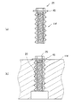
図3〜図5に示されるように、本体部10は全体が角柱状であり、上下に貫通する4カ
所の貫通孔17を有している。貫通孔17は図5に示されるように、上側は螺旋状の溝で
ある螺旋溝(螺旋部)20が設けられた溝孔部21と、溝孔部21の下側でつながる下孔
部22により形成されている。
下孔部22は、断面が円形であって、溝孔部21よりも内径が大きく、座金12やボル
ト25を収納することができる。
As shown in FIGS. 3 to 5, the
The
本体部10の材質は、特に限定されるものでないが、ガラス長繊維強化硬質合成樹脂発
泡体によって構成されている。具体的には、硬質ウレタン樹脂をガラス長繊維で補強した
発泡体である、商品名「エスロンネオランバーFFU」(積水化学工業株式会社製)が用
いられている。
Although the material of the main-
また、本体部10の材質は、他の材質を用いることができる。例えば、ガラス長繊維強
化硬質合成樹脂発泡体として、ガラス繊維、炭素繊維、金属繊維、セラミック繊維等の無
機質繊維、芳香族ポリアミド繊維等の合成繊維や天然繊維等の有機質繊維等を補強材とし
て含み、マトリクスとして、ウレタン樹脂、エポキシ樹脂、ビニルエステル樹脂、不飽和
ポリエステル樹脂、フェノール樹脂などの熱硬化樹脂等の発泡体を用いることができる。
また、圧縮強度の向上や低コスト化を図るために、発泡樹脂中に炭酸カルシウム、石膏、
タルク、水酸化アルミニウム、クレー等の無機充填材、シラスバルーン、パーライト、ガ
ラスバルーン等の軽量骨材などの各種添加材が添加されたものも用いることができる。
In addition, other materials can be used as the material of the
In order to improve compressive strength and reduce costs, calcium carbonate, gypsum,
A material to which various additives such as inorganic fillers such as talc, aluminum hydroxide and clay, and lightweight aggregates such as shirasu balloon, pearlite and glass balloon are added can also be used.
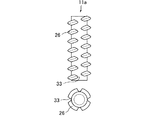
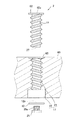
筒状体11は、図4、図5に示されるように、円筒状であって外部には螺旋状の突起で
ある係止部26が設けられ、内部には雌ねじ部27が設けられている。係止部26は、凸
状であり、本体部10の螺旋溝20と螺合できるように、係止部26の断面形状と螺旋溝
20の断面形状をほぼ同じとして、係止部26のピッチと本体部10の螺旋溝20のピッ
チとを同じにしている。
雌ねじ部27は、図4に示されるように、タイプレート80と本体部10とを固定する
ボルト92のねじ部92aに合わせて形成され、上下方向に貫通するように設けられてい
る。そして、後述するまくら木1の筒状体11の雌ねじ部27にボルト92を用いてタイ
プレート80が固定される。
As shown in FIGS. 4 and 5, the
As shown in FIG. 4, the
筒状体11の雌ねじ部27の中心軸と、外部に設けられた係止部26の中心軸とは同一
軸となるように構成されている。したがって、筒状体11を貫通孔17に挿入する場合に
、回転によって軸がずれたり傾いたりすることがない。
The central axis of the
筒状体11の材質は、特に限定されるものではなく、金属や樹脂が用いられている。ま
た、雌ねじ部27付近を金属性として、外側を樹脂により構成しても良い。
The material of the
座金12は、筒状体11の下側に位置しており、筒状体11と連結して筒状体11の上
方への離脱を防止するものである。座金12にはボルト25のねじ部25aが挿入可能な
孔部12aが設けられている。そして、図4に示されるように、ボルト25を筒状体11
の雌ねじ部27の下側で締結するすることにより、座金12と筒状体11とを連結してい
る。なお、このボルト25と座金12は、一体化されたものでも良い。
The
The
次に、本実施形態におけるまくら木1の製造方法について説明する。
まず、本体部10を所定の形状に成形する。具体的には、まくら木1の長手方向に繊維
が配向するように角柱状に成形した後、4カ所の貫通孔17を形成する。そして、上記し
たように、螺旋溝20が形成された溝孔部21と、溝孔部21の下側でつながる下孔部2
2によりドリル加工などにより形成する。
Next, the manufacturing method of the
First, the
2 is formed by drilling or the like.
そして、筒状体11を貫通孔17の上方又は下方から挿入する。このとき、接着剤を塗
布して筒状体11を貫通孔17にねじ込みながら接着剤の充填を行う。この接着剤は、筒
状体11の挿入時には液体状であり、挿入後に養生硬化するものであり、筒状体11と貫
通孔17との接着強度が高い方が望ましい。
Then, the
筒状体11を貫通孔17に挿入する際には、筒状体11を回転しながら挿入する。そし
て、筒状体11の係止部26が貫通孔17の螺旋溝20に誘導されながら、進入していく
。そして、筒状体11の上端面30が本体部10と同じ面上となるようになるまで進入さ
せる。
When inserting the
次に、貫通孔17の下方側から、座金12及びボルト25を取り付ける。具体的には、
図4、図5に示されるように、ボルト25のねじ部25aを座金12の孔部12aに挿入
して、ねじ部25aを雌ねじ部27の下側で締結して、座金12と筒状体11とを連結す
る。このボルト25のねじ部25aには接着剤を塗布しておくと筒状体11のゆるみ止め
にもなる。
Next, the
As shown in FIGS. 4 and 5, the
さらに、貫通孔17の下孔部22に接着剤を充填して硬化させ、接着剤充填部31によ
り、下孔部22を埋めて本体部10の下面側と同一平面状にする。また、接着剤充填部3
1によって、ボルト25の回転止めとなる。
Further, the
1 prevents the
まくら木1を使用する場合については、従来技術と同様に使用することができる。すな
わち、図4に示されるように、雌ねじ部27と締結可能なねじ部92aを有するボルト9
2を用いて、タイプレート80を連結することができる。
About the case where the
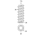
2 can be used to link the
上記した第1の実施形態では、筒状体11の係止部26の断面形状は、全域に渡り同じ
形状であったが、図6〜図8に示される筒状体11a、11b、11cのように、係止部
26の形状が不連続であってもよい。
In the first embodiment described above, the cross-sectional shape of the locking
図6に示される筒状体11aは、係止部26が連続せず切れており、その切れ目33は
筒状体11aの軸方向に平行な方向に配置されている。また、切れ目33は、90°おき
に4カ所設けられている。
In the
図7に示される筒状体11bは、係止部26が径方向に低い部分である溝部34が設け
られており、その溝部34は筒状体11bの軸方向に平行な方向に配置されている。また
、溝部34は、90°おき4カ所に設けられている。
The
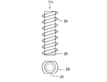
図8に示される筒状体11cは、係止部26が軸方向に平行な平面となるように形成さ
れた部分であるカット部35が設けられている。カット部35は、180°おきに2カ所
設けられている。
The
筒状体11a、11b、11cを、貫通孔17に挿入して接着剤を充填すると、切れ目
33、溝部34、カット部35に接着剤が浸入して硬化する。そして、この状態で筒状体
11a、11b、11cは、上記浸入して硬化した接着剤により、回転が妨げられること
となる。
When the
上記した実施形態の筒状体11、11a、11b、11cの係止部26は凸状であった
が、図9に示される筒状体11eのように、係止部26を凹状として、貫通孔17に螺旋
溝20を螺旋状の突起としても良い。
The locking
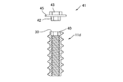
また、図10に示されるように、雌ねじ部27の上側を角穴状の角穴部40を設けた筒
状体11dを用いることができる。そして、挿入部42、操作部43及び鍔部45が設け
られた着脱工具41を用いて、貫通孔17内での筒状体11dの移動を容易にできるよう
にしても良い。具体的には、着脱工具41の挿入部42は角状であって角穴部40に挿入
可能であり、着脱工具41のトルクを筒状体11dに伝達することができる。また、操作
部43は、そのまま、或いは、別途設けられる工具を接続して回転を行うことができるも
のであり、筒状体11dでは、六角形状の突起である。
Further, as shown in FIG. 10, a
そして、筒状体11dの挿入時や取り外し時には、挿入部42を角穴部40に挿入して
着脱工具41を回転して行う。具体的には、まくら木1の製造時には着脱工具41を用い
て筒状体11dを挿入し、また、まくら木1の補修の時には着脱工具41を用いて筒状体
11dを外して、新たな筒状体11dを貫通孔17に入れる等して行うことができる。
また、着脱工具41には鍔部45が設けられているので、筒状体11dの挿入の際に、
鍔部45が本体部10の上面に接触するまで、挿入を行うことにより、筒状体11dの上
端面30を本体部10の上面を容易に合わせることができる。
When the
In addition, since the
By inserting until the
また、上記した着脱工具41の代わりに、ボルト25を用いて、筒状体11fの挿入・
取り外しを行うことができる。これは、図12(a)に示されるように、筒状体11fの
上側を座金12を挿入してボルト25を取り付け、この状態で、図12(b)に示すよう
に、螺旋溝20に挿入する。
Further, instead of the above-described attaching / detaching
Removal can be performed. As shown in FIG. 12A, the
そして、上記した実施形態と同様に、下側に、座金12を挿入した状態で、ボルト25
を挿入して固定する。この方法によれば、下側のボルト25による固定の際に、上下方向
に挟み付けるようにすることができるので、確実な接合、一体化が図れる。
なお、上側のボルト25と座金12は取り外される。
And like the above-mentioned embodiment, in the state which inserted the
Insert and fix. According to this method, when the
The
また、本発明の第2の実施形態のまくら木2は図11に示されている。そして、まくら
木2は、本体部60及び上板62と、第1の実施形態のまくら木1と同様の筒状体11、
座金12及びボルト25を有している。
A
It has a
本体部60は、貫通孔17の上側に凹部65が設けられている以外は、第1の実施形態
のまくら木1の本体部10と同様である。凹部65は、溝孔部21の上側であって、その
軸方向に垂直断面の大きさは、溝孔部21よりも大きい。
The
上板62は筒状体11に固定されている。そして、上板62の形状と凹部65の形状と
あの関係は、貫通孔17の中心軸をを中心として、上板62を凹部65内で回転させるこ
とができるものである。また、上板62の外形は雌ねじ部27よりも大きく、また、軸方
向に貫通する貫通孔62aが設けられている。
また、上板62の厚みと凹部65の深さはほぼ同じである。
The
Further, the thickness of the
まくら木2を組み立てる際には、貫通孔17の上側から筒状体11及び上板62が一体
となった部材を挿入していく。そして、上板62が凹部65に嵌りこんだ状態として、ま
くら木2の上側が平面状となるようにする。なお、上板62は凹部65内で回転できるの
で、挿入の邪魔になることはない。
なお、筒状体11及び上板62が一体となった部材を挿入する工程以外については、上
記した実施形態と同様な工程で製造される。
When assembling the
In addition, except the process of inserting the member which the
まくら木2では、筒状体11を貫通孔17に挿入後、ボルト25を筒状体11の雌ねじ
部27に締結することにより、上板62と座金12とにより本体部60が挟まれて、筒状
体11の固定がより確実となる。
In the
上記したまくら木1、2では、雌ねじ部27を用いて、タイプレート80を連結するも
のであったが、雌ねじ部27を用いてまくら木1、2に連結するものであればどのような
ものでも用いることができる。
In the
筒状体11、11a、11b、11c、11d、11e、11f、ボルト25、座金1
2の材質は金属などを用いることができ、特に限定されないが、樹脂製とすることができ
る。そして、これら全てを樹脂製とすることにより、まくら木1、2のリユースやリサイ
クルなどの際に、金属を含まないので処理を行いやすい。この場合、まくら木1、2の本
体部10、60の材質に合わせることが望ましい。また、筒状体11、11a、11b、
11c、11d、11e、11fを金属製とし、ボルト25、座金12を樹脂製として、
使用後に筒状体11、11a、11b、11c、11d、11e、11fのみを取り外し
てもよい。
The material of 2 can use a metal etc., Although it does not specifically limit, It can be made from resin. By making all of them resinous, when the
11c, 11d, 11e, and 11f are made of metal, and the
You may remove only the
1、2 まくら木
10、60 本体部
11、11a、11b、11c、11d、11e、11f 筒状体
12 座金
17 貫通孔
20 螺旋溝(螺旋部)
26 係止部
27 雌ねじ部
40 角穴部
41 着脱工具
42 挿入部
43 操作部
45 鍔部
62 上板
1, 2,
26
Claims (10)
る座金を有し、前記筒状体は貫通孔に配置されて隙間に接着剤を充填し、本体部の下側に
座金を配置して筒状体の上方への抜け防止を行いながら筒状体と本体部とを固定し、筒状
体の雌ねじを用いて締結装置との締結を行うことができるまくら木において、前記筒状体
は雌ねじの軸を中心軸とする円柱状であって、所定のピッチで螺旋状に形成された係止部
が設けられており、本体部の貫通孔には前記係止部に対応する螺旋部が設けられて本体部
と筒状体とを螺合していることを特徴とするまくら木。 A main body provided with a through hole; a cylindrical body provided with an internal thread; and a washer connected to the cylindrical body. The cylindrical body is disposed in the through hole, and an adhesive is provided in the gap. Fill and place the washer under the main body part to prevent the cylindrical body from being pulled upward, and fix the cylindrical body and the main body part, and fasten with the fastening device using the internal thread of the cylindrical body In the sleeper, the cylindrical body has a columnar shape with the axis of the female screw as a central axis, and is provided with a locking portion formed in a spiral shape at a predetermined pitch, and is penetrated through the body portion. A sleeper characterized in that a spiral portion corresponding to the locking portion is provided in the hole, and the main body portion and the cylindrical body are screwed together.
ていることを特徴とする請求項1に記載のまくら木。 The sleeper according to claim 1, wherein the locking portion of the cylindrical body or the spiral portion of the through hole is convex and has a discontinuous portion in cross-sectional shape.
でいることを特徴とする請求項1又は2に記載のまくら木。 The sleeper according to claim 1 or 2, wherein an upper plate connected to the cylindrical body is provided on the upper side of the main body, and the main body is sandwiched between the upper plate and a washer.
とする請求項1〜3いずれかに記載のまくら木。 The pillow according to any one of claims 1 to 3, wherein a square hole portion larger than an inner diameter of the female screw portion is provided on an upper end side of the female screw portion.
くら木。 The pillow according to any one of claims 1 to 4, wherein the cylindrical body is made of metal.
くら木。 The sleeper according to any one of claims 1 to 4, wherein the cylindrical body is made of resin.
る請求項1〜6いずれかに記載のまくら木。 The sleeper according to any one of claims 1 to 6, wherein the main body portion is constituted by a long glass fiber reinforced hard synthetic resin foam.
角穴部に対応する形状である挿入部とを有する着脱工具を用い、挿入部を角穴部に挿入し
ながら操作部を回転させて筒状体の挿入する工程を有する特徴とするまくら木の製造方法
。 A sleeper manufacturing method for manufacturing the sleeper according to any one of claims 4 to 7, comprising: an operation unit;
Using a detachable tool having an insertion portion having a shape corresponding to a square hole portion, and manufacturing the sleeper wood, the step of rotating the operation portion while inserting the insertion portion into the square hole portion and inserting the cylindrical body Method.
、前記鍔部がまくら木の本体部に接触するまで行うものであることを特徴とする請求項8
に記載のまくら木の製造方法。 A hook part is provided between the insertion part and the operation part of the detachable tool, and the step of inserting the cylindrical body is performed until the hook part contacts the main body part of the sleeper. Item 8
The manufacturing method of the sleeper tree as described in 2.
角穴部に対応する形状である挿入部とを有する着脱工具を用い、挿入部を角穴部に挿入し
ながら操作部を回転させて筒状体を貫通孔から取り出す工程を有することを特徴とするま
くら木の補修方法。 A sleeper repair method for repairing a sleeper according to any one of claims 4 to 7, comprising: an operation unit;
Using a detachable tool having an insertion part having a shape corresponding to the square hole part, and having a step of rotating the operation part while inserting the insertion part into the square hole part and taking out the cylindrical body from the through hole, How to repair sleeper trees.
Priority Applications (1)
| Application Number | Priority Date | Filing Date | Title |
|---|---|---|---|
| JP2004107561A JP2005290844A (en) | 2004-03-31 | 2004-03-31 | Sleeper tree, sleeper tree manufacturing method and sleeper tree repair method |
Applications Claiming Priority (1)
| Application Number | Priority Date | Filing Date | Title |
|---|---|---|---|
| JP2004107561A JP2005290844A (en) | 2004-03-31 | 2004-03-31 | Sleeper tree, sleeper tree manufacturing method and sleeper tree repair method |
Publications (1)
| Publication Number | Publication Date |
|---|---|
| JP2005290844A true JP2005290844A (en) | 2005-10-20 |
Family
ID=35324090
Family Applications (1)
| Application Number | Title | Priority Date | Filing Date |
|---|---|---|---|
| JP2004107561A Pending JP2005290844A (en) | 2004-03-31 | 2004-03-31 | Sleeper tree, sleeper tree manufacturing method and sleeper tree repair method |
Country Status (1)
| Country | Link |
|---|---|
| JP (1) | JP2005290844A (en) |
Cited By (8)
| Publication number | Priority date | Publication date | Assignee | Title |
|---|---|---|---|---|
| KR100706323B1 (en) * | 2005-12-24 | 2007-04-13 | 한국철도기술연구원 | Bolted structure of segmented precast concrete sleepers |
| JP2007254981A (en) * | 2006-03-22 | 2007-10-04 | Nhk Spring Co Ltd | Synthetic sleeper and molding method thereof |
| JP2008280689A (en) * | 2007-05-09 | 2008-11-20 | Nhk Spring Co Ltd | Synthetic sleepers |
| JP2010229784A (en) * | 2009-03-30 | 2010-10-14 | Hokkaido Railway Co | Rail fastening device |
| CN102245836A (en) * | 2008-12-10 | 2011-11-16 | 佛斯洛威克有限公司 | Screw anchor with conical head for rail attachment |
| JP2018199924A (en) * | 2017-05-26 | 2018-12-20 | 積水化学工業株式会社 | Method for manufacturing sleepers |
| JP2019078013A (en) * | 2017-10-20 | 2019-05-23 | 積水化学工業株式会社 | Sleeper and sleeper assembly method |
| CN114134764A (en) * | 2020-09-03 | 2022-03-04 | 洛阳科博思新材料科技有限公司 | Sleeper structure capable of repairing railway spike looseness and railway spike looseness repairing method |
-
2004
- 2004-03-31 JP JP2004107561A patent/JP2005290844A/en active Pending
Cited By (8)
| Publication number | Priority date | Publication date | Assignee | Title |
|---|---|---|---|---|
| KR100706323B1 (en) * | 2005-12-24 | 2007-04-13 | 한국철도기술연구원 | Bolted structure of segmented precast concrete sleepers |
| JP2007254981A (en) * | 2006-03-22 | 2007-10-04 | Nhk Spring Co Ltd | Synthetic sleeper and molding method thereof |
| JP2008280689A (en) * | 2007-05-09 | 2008-11-20 | Nhk Spring Co Ltd | Synthetic sleepers |
| CN102245836A (en) * | 2008-12-10 | 2011-11-16 | 佛斯洛威克有限公司 | Screw anchor with conical head for rail attachment |
| JP2010229784A (en) * | 2009-03-30 | 2010-10-14 | Hokkaido Railway Co | Rail fastening device |
| JP2018199924A (en) * | 2017-05-26 | 2018-12-20 | 積水化学工業株式会社 | Method for manufacturing sleepers |
| JP2019078013A (en) * | 2017-10-20 | 2019-05-23 | 積水化学工業株式会社 | Sleeper and sleeper assembly method |
| CN114134764A (en) * | 2020-09-03 | 2022-03-04 | 洛阳科博思新材料科技有限公司 | Sleeper structure capable of repairing railway spike looseness and railway spike looseness repairing method |
Similar Documents
| Publication | Publication Date | Title |
|---|---|---|
| US10030686B2 (en) | Anchor for fixing in a wall | |
| JP2005290844A (en) | Sleeper tree, sleeper tree manufacturing method and sleeper tree repair method | |
| US20030092334A1 (en) | Removable and adjustable surf fin system | |
| CN213507832U (en) | Sleeper structure capable of repeatedly dismounting spike | |
| JP5926615B2 (en) | Shaft wall structure and construction method | |
| KR102236170B1 (en) | Combined structure for fixing building exterior materials | |
| JP5232087B2 (en) | Sleeper tree and sleeper tree manufacturing method | |
| JP4065957B2 (en) | Anchor integrated liner and equipment installation method | |
| WO2012146283A1 (en) | A method and a device for fastening an object in a fiber-reinforced composite material | |
| JP2007054344A (en) | Frame member, fastener, and structure using them | |
| JPWO2008053542A1 (en) | Anchor, its fixing method and fixing structure using the same | |
| KR20070003424A (en) | Fiber-reinforced plastic tendons with polygonal columnar shapes and their anchorages | |
| KR20180032151A (en) | Punch bolts to repair punctures in the structure | |
| JP4587385B2 (en) | How to embed anchor metal fittings that are not tied to reinforcing bars | |
| JP5207070B2 (en) | Joining structure to the concrete structure of the member to be joined | |
| JP2019218726A (en) | Reinforcement anchor | |
| JP4848567B2 (en) | Synthetic sleepers | |
| JP5771467B2 (en) | Building unit positioning structure, building unit positioning method, and unit guide installation method | |
| US11092182B2 (en) | Drive screw | |
| CN223781827U (en) | A mechanical anchor | |
| US4601092A (en) | Method of fixing a rail on a support of timber or cast or moulded material | |
| JP2002161501A (en) | Synthetic sleeper, rail support device having the synthetic sleeper, and method of manufacturing the synthetic sleeper | |
| KR20150110146A (en) | Anchor bolt unit and method for manufacturing anchor bolt unit | |
| JP2024097130A (en) | Reinforcement structure of masonry wall, reinforcement method of masonry wall, and support device for steel bar for reinforcing masonry wall | |
| JP7271531B2 (en) | Sleepers and methods for manufacturing sleepers |