JP2005290818A - Construction method such as pc tilting form for dam construction and dam levee body or the like - Google Patents
Construction method such as pc tilting form for dam construction and dam levee body or the like Download PDFInfo
- Publication number
- JP2005290818A JP2005290818A JP2004106767A JP2004106767A JP2005290818A JP 2005290818 A JP2005290818 A JP 2005290818A JP 2004106767 A JP2004106767 A JP 2004106767A JP 2004106767 A JP2004106767 A JP 2004106767A JP 2005290818 A JP2005290818 A JP 2005290818A
- Authority
- JP
- Japan
- Prior art keywords
- plate
- wall plate
- anchor bolt
- mold
- concrete
- Prior art date
- Legal status (The legal status is an assumption and is not a legal conclusion. Google has not performed a legal analysis and makes no representation as to the accuracy of the status listed.)
- Granted
Links
- 238000010276 construction Methods 0.000 title claims abstract description 27
- NJPPVKZQTLUDBO-UHFFFAOYSA-N novaluron Chemical compound C1=C(Cl)C(OC(F)(F)C(OC(F)(F)F)F)=CC=C1NC(=O)NC(=O)C1=C(F)C=CC=C1F NJPPVKZQTLUDBO-UHFFFAOYSA-N 0.000 claims abstract description 47
- 239000004567 concrete Substances 0.000 claims description 85
- 230000001681 protective effect Effects 0.000 claims description 49
- 238000009415 formwork Methods 0.000 claims description 38
- XLYOFNOQVPJJNP-UHFFFAOYSA-N water Substances O XLYOFNOQVPJJNP-UHFFFAOYSA-N 0.000 claims description 34
- 238000009434 installation Methods 0.000 claims description 22
- 230000005484 gravity Effects 0.000 claims description 13
- 238000000034 method Methods 0.000 claims description 12
- 238000003780 insertion Methods 0.000 claims description 6
- 230000037431 insertion Effects 0.000 claims description 6
- 238000002347 injection Methods 0.000 claims description 5
- 239000007924 injection Substances 0.000 claims description 5
- 238000010030 laminating Methods 0.000 claims description 3
- 238000007789 sealing Methods 0.000 claims description 2
- 238000004904 shortening Methods 0.000 abstract description 3
- XEEYBQQBJWHFJM-UHFFFAOYSA-N Iron Chemical compound [Fe] XEEYBQQBJWHFJM-UHFFFAOYSA-N 0.000 description 20
- 229910052742 iron Inorganic materials 0.000 description 10
- 239000002184 metal Substances 0.000 description 9
- 229910052751 metal Inorganic materials 0.000 description 9
- 239000004570 mortar (masonry) Substances 0.000 description 8
- 239000000725 suspension Substances 0.000 description 6
- 238000005520 cutting process Methods 0.000 description 5
- 239000000463 material Substances 0.000 description 3
- 239000011178 precast concrete Substances 0.000 description 2
- 238000007788 roughening Methods 0.000 description 2
- 238000011144 upstream manufacturing Methods 0.000 description 2
- 229910000831 Steel Inorganic materials 0.000 description 1
- 230000032683 aging Effects 0.000 description 1
- 238000005266 casting Methods 0.000 description 1
- 238000010586 diagram Methods 0.000 description 1
- 230000002265 prevention Effects 0.000 description 1
- 239000004576 sand Substances 0.000 description 1
- 238000005488 sandblasting Methods 0.000 description 1
- 239000010959 steel Substances 0.000 description 1
- 230000035882 stress Effects 0.000 description 1
Images

Landscapes
- Retaining Walls (AREA)
Abstract
Description
本発明は、台形CSGダムなどの斜面の施工に際して、PC傾斜型枠を用いることによって、施工を簡易化でき、しかも工期の短縮を可能にする技術に関する。 The present invention relates to a technique that can simplify the construction and shorten the construction period by using a PC inclined mold when constructing a slope such as a trapezoidal CSG dam.
PC(プレキャスト)型枠およびその組立て方法として、特開平8−199708号公報に記載のように、工事現場でのセットや組立てが容易で、基本的には型枠支保が不要で、作業性がよく、後打ちコンクリートとの一体性も確保でき、構造物の一部として機能させる技術が提案されている。このPC型枠利用工法は、外方に突出する上段パネルと該上段パネルと段部を介してこれに連続して形成される内方に突出する下段パネルとで型枠パネルを構成し、組立てに際しては、下方の型枠パネルの上段パネルの裏面に、上方の型枠パネルの下段パネルの表面を重ね合わせる施工方法を採っている。 As described in JP-A-8-199708, PC (precast) formwork and its assembly method are easy to set and assemble at the construction site, basically no formwork support is required and workability is improved. Well, there is a proposal for a technique that can ensure integrity with post-cast concrete and function as part of a structure. In this PC formwork construction method, an upper panel protruding outward and a lower panel protruding inward through the upper panel and the stepped portion are formed into an assembly panel. At this time, a construction method is employed in which the surface of the lower panel of the upper formwork panel is superimposed on the back surface of the upper panel of the lower formwork panel.
また、別の工法として、実開平6-14225号公報に記載のように、ブロックにしてコンクリート構造物の足場および型枠を省略して構造物の一部となし、しかもブロックを簡単かつ確実に据え付け固定し、構造物の美的外観を得るために、法壁用プレキャストコンクリートブロックは、平板状の前面部と、後面部の左右両端部に設けられた切りかき溝部と、固定金具と、リフトアンカー金具と、ストッパー金具を設けた構造になっている。
ところが、特許文献1のようなPC型枠は、組立て施工時のPC型枠の支えが困難なため、特別な支持構造が必要となり、特に法面のように傾斜した場所には適しない。また、上段パネルと下段パネルを重ねて使用するため、すべて2枚重ねとなり、作業工数増加の要因となり、能率的とはいえない。
However, since the PC form as in
特許文献2の技術も、法壁用プレキャストコンクリートブロックを一定の角度で規定の位置に精度良く据え付ける作業が困難であり、また据え付け後は、重機で前記ブロックを吊った状態で、後面部に埋め込まれている固定金具と構造物本体に埋め込まれている固定用フックとを連結鉄棒で連結して、溶接又はネジ止めする必要があり、支持作業が面倒で、危険でもある。
In the technique of
本発明の技術的課題は、従来技術におけるこのような問題に着目し、PC型枠を用いて、ダム堤体や法面などのような傾斜面を施工する際に、PC型枠を自立可能な構造とすることによって、PC型枠の据え付け作業の簡易化を図り、しかも簡易な固定だけで、後打ちコンクリートの打設が可能とすることにある。 The technical problem of the present invention is that such a problem in the prior art is focused on, and when using a PC formwork to construct an inclined surface such as a dam dam body or a slope, the PC formwork can be self-supporting. By adopting a simple structure, it is possible to simplify the installation work of the PC formwork and to allow the placement of post-cast concrete only by simple fixing.
本発明の技術的課題は次のような手段によって解決される。請求項1は、ダム堤体や法面などの斜面を施工する際に用いるPC傾斜型枠であって、水平の台座版と一体の斜壁版を有し、前記台座版と斜壁版との連続部正面に鉛直面を有し、前記斜壁版の頂端背面にも鉛直面を有していて、下段の斜壁版の頂端背面の鉛直面の背部に、上段の台座版正面の鉛直面が配置される構造となっていることを特徴とするPC傾斜型枠である。
The technical problem of the present invention is solved by the following means.
このように、水平の台座版と一体の斜壁版を有し、前記台座版と斜壁版との連続部の正面が鉛直面になっている。また、前記斜壁版の頂端背面も鉛直面になっている。使用に際しては、下段の斜壁版の頂端背面の鉛直面の背部に、上段の台座版正面の鉛直面が配置されるため、基礎コンクリートや構造物の平坦面の上に台座版を設置することによって、容易にPC型枠を据えつけることができる。さらに、斜壁版の頂端背面の鉛直面を基準にして、上段の台座版正面の鉛直面を位置決めできるので、多数のPC型枠を位置決めし据えつけるのに極めて便利であり、作業能率が良いので、工期の短縮も可能となる。 Thus, it has a slant wall plate integral with a horizontal base plate, and the front of the continuous part of the base plate and the slant wall plate is a vertical surface. In addition, the back of the top end of the inclined wall plate is also a vertical surface. When using, the vertical plane in front of the upper pedestal plate is placed behind the vertical surface behind the top of the lower slant wall plate, so the pedestal plate must be installed on the flat surface of the foundation concrete or structure. The PC formwork can be easily installed. Furthermore, since the vertical plane on the front of the upper pedestal plate can be positioned with reference to the vertical plane on the back of the top end of the slanted wall plate, it is extremely convenient for positioning and installing a large number of PC formwork and has high work efficiency. Therefore, the construction period can be shortened.
請求項2は、前記の台座版の平面領域内に、前記PC傾斜型枠全体の重心が位置するように、前記台座版と斜壁版との連続部の背面にも鉛直面を形成してあり、この背面の鉛直面と前記の連続部正面の鉛直面との間の版厚を、前記の斜壁版および台座版の版厚より大きくしてあることを特徴とする請求項1に記載のPC傾斜型枠である。 According to a second aspect of the present invention, a vertical surface is also formed on the back surface of the continuous portion of the pedestal plate and the slanted wall plate so that the center of gravity of the entire PC inclined mold is located in the plane area of the pedestal plate. The plate thickness between the vertical surface of the back surface and the vertical surface of the continuous portion front surface is larger than the plate thicknesses of the slanted wall plate and the pedestal plate. It is a PC inclined formwork.
このように、前記台座版と斜壁版との連続部の背面にも鉛直面を形成し、この背面の鉛直面と前記の連続部正面の鉛直面との間の版厚を、前記の斜壁版および台座版の版厚より大きくして重くしてあるため、PC傾斜型枠全体の重心を台座版の平面領域内に位置させることができる。その結果、台座版を平坦な面上に置くだけで、PC傾斜型枠が安定するので、据え付け作業が極めて容易になる。しかも、最も大きな荷重が作用する場所である、台座版と斜壁版との連続部の版厚が大きいので、強度強化にもなる。 In this way, a vertical surface is also formed on the back surface of the continuous portion of the pedestal plate and the inclined wall plate, and the plate thickness between the vertical surface of the back surface and the vertical surface of the continuous portion front surface is set to the inclined surface. Since it is larger and heavier than the plate thickness of the wall plate and the pedestal plate, the center of gravity of the entire PC inclined mold can be positioned in the plane area of the pedestal plate. As a result, the PC inclined mold can be stabilized simply by placing the pedestal plate on a flat surface, so that the installation work becomes extremely easy. In addition, since the plate thickness of the continuous portion between the pedestal plate and the inclined wall plate where the largest load acts is large, the strength is also enhanced.
請求項3は、前記の斜壁版において、前記PC傾斜型枠の重心位置を吊り上げ可能な位置に、着脱可能な吊り金具を仮止め可能となっていることを特徴とする請求項1または請求項2に記載のPC傾斜型枠である。このように、前記の斜壁版において、前記PC傾斜型枠の重心位置を吊り上げ可能な位置に、吊り金具を仮止め可能にしてあるため、重機などで吊り金具を用いて吊り上げた際に、PC傾斜型枠の台座版が水平となる。したがって、据え付け作業が極めて容易になる。また、吊り金具は、斜壁版に対し着脱可能なため、据え付け完了後は、取り外して、ボルト孔をモルタルで塞ぐことができる。
According to a third aspect of the present invention, in the slanted wall plate, a detachable hanging bracket can be temporarily fixed at a position where the center of gravity of the PC inclined mold can be lifted.
請求項4は、前記の台座版において、据え付け状態で互いに隣接する端部側に、止水板の被りを確保できる逃げ空間が形成されていることを特徴とする請求項1、請求項2または請求項3に記載のPC傾斜型枠である。このように、台座版には、互いに隣接する端部側に、止水板を設置して被りを確保できるだけの逃げ空間が形成されているので、PC傾斜型枠を並べて据えつけた状態で止水板を配置して後打ちコンクリート中に埋め込むことができ、しかも止水板に対する被りも十分に確保できる。また、各PC傾斜型枠にこの逃げ空間を確保するには、左右両端に設けることになるが、その結果、PC傾斜型枠の軽量化とコンクリート材料の節減にもなる。
According to a fourth aspect of the present invention, in the pedestal plate, a clearance space capable of securing the covering of the water stop plate is formed on the side of the adjacent ends in the installed state. It is a PC inclination type | mold form of
請求項5は、前記の斜壁版の背面がジェット噴射などの手法によって粗面化されていることを特徴とする請求項1から請求項4までのいずれかの項に記載のPC傾斜型枠である。ジェット噴射は、粗面化法の一例である。このように、前記斜壁版の背面がジェット水噴射などの手法によって粗面化されているため、後打ちコンクリートを打設した際に互いに密着して強固に結合されるので、確実に一体化される。
5. The inclined PC form according to any one of
請求項6は、PC傾斜型枠の水平の台座版において、アンカーボルト挿入孔を開けてあり、しかも、スパン方向の両端と中間部に、レベル調整手段を装備してあることを特徴とするPC傾斜型枠である。このように、PC傾斜型枠の水平の台座版にアンカーボルト挿入孔を開けてあるので、下段のPC傾斜型枠の背面に後打ちコンクリートを打設した際に位置決め埋設してあるアンカーボルトを上側のPC傾斜型枠の台座版のアンカーボルト挿入孔に位置合わせして挿入するだけで、各PC傾斜型枠を位置決めでき、その後は必要に応じて微調整してからアンカーボルトをナット締めするだけで、PC傾斜型枠の据え付けができる。台座版には、スパン方向の両端と中間部に、レベル調節手段を装備してあるので、据え付けに際しての水平度の微調整も容易である。
請求項7は、アンカーボルトの固定位置を決める治具であって、水平方向に延びた連結部材の一端に、PC傾斜型枠の斜壁版の頂端背面の鉛直面に仮止め固定する基準部材を有しており、他端には、アンカーボルトを挿入支持する位置決め孔を有していることを特徴とする位置決め治具である。 Claim 7 is a jig for determining a fixing position of the anchor bolt, and is a reference member temporarily fixed to one end of a connecting member extending in the horizontal direction on the vertical surface of the top end rear surface of the inclined wall plate of the PC inclined mold. And a positioning hole for inserting and supporting the anchor bolt at the other end.
このように、上段のPC傾斜型枠の位置決めとなるアンカーボルトを配設する際の設置位置を決める治具において、水平方向に延びた連結部材の一端に、既設のPC傾斜型枠の斜壁版の頂端背面の鉛直面に仮止め固定する基準部材を有しており、他端には、アンカーボルトを挿入支持する位置決め孔を有しているので、据え付け完了したPC傾斜型枠の背部にコンクリート打設した後、当該PC傾斜型枠の斜壁版の頂端背面の鉛直面に、位置決め治具の基準部材を当てて固定し、さらに、他端側の位置決め孔にアンカーボルトを挿入すると共に打設したコンクリート中に挿入し埋め込んだ状態とする。こうして養生し硬化した後に、前記の治具をアンカーボルトおよび斜壁版の頂端背面から取り外すと、前記のアンカーボルトを、上段のPC傾斜型枠を据え付ける際の位置決めに利用できる。なお、前記治具にアンカーボルトを保持させた状態で、背部のコンクリートを打設することも可能であり、順序は限定されない。 In this way, in the jig for determining the installation position when the anchor bolt for positioning the upper PC inclined mold is disposed, the inclined wall of the existing PC inclined mold is attached to one end of the connecting member extending in the horizontal direction. It has a reference member that is temporarily fixed to the vertical surface on the back of the top end of the plate, and a positioning hole for inserting and supporting the anchor bolt at the other end. After placing the concrete, fix the reference jig of the positioning jig against the vertical surface of the top end of the inclined wall plate of the PC inclined mold, and insert the anchor bolt into the positioning hole on the other end side. Inserted and embedded in the cast concrete. When the jig is removed from the anchor bolt and the back of the top end of the slant wall plate after being cured and cured in this way, the anchor bolt can be used for positioning when installing the upper PC inclined formwork. In addition, it is also possible to place the back concrete with the anchor bolt held by the jig, and the order is not limited.
請求項8は、ダム堤体などの斜面の施工構造であって、CSG部と自立させて据え付けしたPC傾斜型枠との間の空間部に、後打ちコンクリートとして保護遮水コンクリートを打設してなる構造を、複数段積層施工してなることを特徴とする斜面構造である。このように、CSG部と自立させて据え付けしたPC傾斜型枠との間の空間部に後打ちコンクリートを打設してなる構造を、複数回重ねて施工することによって、複数段を積層して施工した構造とすることによって、所望の高さのダム堤体などにおける上流側および下流側、あるいはダム以外の通常の法面なども効率的に実現でき、施工期間の短縮と経費節減が実現される。
請求項9は、前記のPC傾斜型枠は、水平の台座版と一体の斜壁版を有しており、隣接するPC傾斜型枠の隣接する前記斜壁版において、少なくとも斜壁版の内面に、隣接するPC傾斜型枠間の隙間をシールするための遮水性のテープを貼ってあることを特徴とする請求項8に記載の斜面構造である。このように、前記のPC傾斜型枠は、水平の台座版と一体の斜壁版を有しており、隣接するPC傾斜型枠の隣接する前記斜壁版において、少なくとも斜壁版の内面に、隣接するPC傾斜型枠間の隙間をシールするための遮水性のテープを貼ってあるため、複数のPC傾斜型枠を水平ならびに上下方向に並べて多数据え付けて、ダム堤体などの斜面を施工した場合、左右の隣接する斜壁版間の隙間から水漏れしたり、PC傾斜型枠の背面に後打ちコンクリートを打設する際にモルタル分(のろ)が漏れだすのを防ぐことができる。
According to a ninth aspect of the present invention, the PC inclined mold has a slanted wall plate integrated with a horizontal pedestal plate, and in the adjacent slanted wall plate of the adjacent PC inclined mold, at least the inner surface of the slanted wall plate. 9. The slope structure according to
請求項10は、下段のCSG部とPC傾斜型枠との間に打設した保護遮水コンクリート中に、下段のPC傾斜型枠の斜壁版の頂端内面の鉛直面を基準にして、治具を用いて位置決めしたアンカーボルトを挿入した状態において、前記の保護遮水コンクリートが硬化した後に、前記の治具を除去して、前記のアンカーボルトが上段のPC傾斜型枠の台座版のアンカーボルト孔に入るように位置決めして固定してから、上段のPC傾斜型枠とCSG部との間に保護遮水コンクリートを打設することを特徴とするPC傾斜型枠を用いた斜面部の施工方法である。
According to
このように、下段のCSG部とPC傾斜型枠との間に打設した保護遮水コンクリート中に、下段のPC傾斜型枠の斜壁版の頂端内面の鉛直面を基準にして、治具を用いて位置決めしたアンカーボルトを挿入し、保護遮水コンクリートを硬化させる。そして、硬化後に前記の治具を除去して、前記のアンカーボルトが上段のPC傾斜型枠の台座版のアンカーボルト孔に入るように位置決めして固定してから、上段のPC傾斜型枠とCSG部との間に保護遮水コンクリートを打設する。そのため、CSG部の打設と、PC傾斜型枠の据え付けと、保護遮水コンクリートの打設と、アンカーボルトの設置とを繰り返すことによって、ダム堤体などの斜面を所望の高さまで施工できる。なお、アンカーボルトの配置後に、保護遮水コンクリートを打設してもよい。つまり、順序は問わない。 In this way, in the protective water-impervious concrete placed between the lower CSG portion and the PC inclined mold, the jig is determined based on the vertical surface of the top end inner surface of the inclined wall plate of the lower PC inclined mold. Insert the anchor bolts positioned using, and harden the protective waterproof concrete. Then, after curing, the jig is removed, and the anchor bolt is positioned and fixed so that the anchor bolt enters the anchor bolt hole of the base plate of the upper PC inclined mold frame, and then the upper PC inclined mold frame and Protective impermeable concrete is placed between the CSG section. Therefore, it is possible to construct a slope such as a dam dam body to a desired height by repeating the placement of the CSG portion, the installation of the PC inclined formwork, the placement of the protective impermeable concrete, and the installation of the anchor bolt. In addition, you may lay protective water-impervious concrete after arrangement | positioning of an anchor bolt. That is, the order does not matter.
請求項1のように、水平の台座版と一体の斜壁版を有し、前記台座版と斜壁版との連続部の正面が鉛直面になっており、前記斜壁版の頂端背面も鉛直面になっている。使用に際しては、下段の斜壁版の頂端背面の鉛直面の背部に、上段の台座版正面の鉛直面が配置されるため、基礎コンクリートや構造物の平坦面の上に台座版を設置することによって、容易にPC型枠を据えつけることができる。さらに、斜壁版の頂端背面の鉛直面を基準にして、上段の台座版正面の鉛直面を位置決めできるので、多数のPC型枠を位置決めし据えつけるのに極めて便利であり、作業能率が良いので、工期の短縮も可能となる。
As in
請求項2のように、前記台座版と斜壁版との連続部の背面にも鉛直面を形成し、この背面の鉛直面と前記の連続部正面の鉛直面との間の版厚を、前記の斜壁版および台座版の版厚より大きくして重くしてあるため、PC傾斜型枠全体の重心を台座版の平面領域内に位置させることができる。その結果、台座版を平坦な面上に置くだけで、PC傾斜型枠が安定するので、据え付け作業が極めて容易になる。しかも、最も大きな荷重が作用する場所である、台座版と斜壁版との連続部の版厚が大きいので、強度強化にもなる。
As in
請求項3のように、前記の斜壁版において、前記PC傾斜型枠の重心位置を吊り上げ可能な位置に、吊り金具を仮止め可能にしてあるため、重機などで吊り金具を用いて吊り上げた際に、PC傾斜型枠の台座版が水平となる。したがって、据え付け作業が極めて容易になる。また、吊り金具は、斜壁版に対し着脱可能なため、据え付け完了後は、取り外して、ボルト孔をモルタルで塞ぐことができる。
As in
請求項4のように、台座版には、互いに隣接する端部側に、止水板を設置して被りを確保できるだけの逃げ空間が形成されているので、PC傾斜型枠を並べて据えつけた状態で止水板を配置して後打ちコンクリート中に埋め込むことができ、しかも止水板に対する被りも十分に確保できる。また、各PC傾斜型枠にこの逃げ空間を確保するには、左右両端に設けることになるが、その結果、PC傾斜型枠の軽量化とコンクリート材料の節減にもなる。
As in
請求項5のように、前記斜壁版の背面がジェット水噴射などの手法によって粗面化されているため、後打ちコンクリートを打設した際に互いに密着して強固に結合されるので、確実に一体化される。 Since the back surface of the slanted wall plate is roughened by a method such as jet water injection as in claim 5, since it is closely bonded to each other when post-cast concrete is placed, Integrated into
請求項6のように、PC傾斜型枠の水平の台座版にアンカーボルト挿入孔を開けてあるので、下段のPC傾斜型枠の背面に後打ちコンクリートを打設した際に位置決め埋設してあるアンカーボルトを上側のPC傾斜型枠の台座版のアンカーボルト挿入孔に位置合わせして挿入するだけで、各PC傾斜型枠を位置決めでき、その後は必要に応じて微調整してからアンカーボルトをナット締めするだけで、PC傾斜型枠の据え付けができる。台座版には、スパン方向の両端と中間部に、レベル調節手段を装備してあるので、据え付けに際しての水平度の微調整も容易である。
Since the anchor bolt insertion hole is formed in the horizontal base plate of the PC inclined mold as in
請求項7のように、上段のPC傾斜型枠の位置決めとなるアンカーボルトを配設する際の設置位置を決める治具において、水平方向に延びた連結部材の一端に、既設のPC傾斜型枠の斜壁版の頂端背面の鉛直面に仮止め固定する基準部材を有しており、他端には、アンカーボルトを挿入支持する位置決め孔を有しているので、据え付け完了したPC傾斜型枠の背部にコンクリート打設した後、当該PC傾斜型枠の斜壁版の頂端背面の鉛直面に、位置決め治具の基準部材を当てて固定し、さらに、他端側の位置決め孔にアンカーボルトを挿入すると共に打設したコンクリート中に挿入し埋め込んだ状態とする。こうして養生し硬化した後に、前記の治具をアンカーボルトおよび斜壁版の頂端背面から取り外すと、前記のアンカーボルトを、上段のPC傾斜型枠を据え付ける際の位置決めに利用できる。 8. A jig for determining an installation position when an anchor bolt for positioning an upper PC inclined mold is provided as in claim 7, wherein an existing PC inclined mold is attached to one end of a connecting member extending in the horizontal direction. PC tilting formwork that has been installed because it has a reference member that is temporarily fixed to the vertical surface on the back of the top end of the slanted wall plate, and a positioning hole that inserts and supports the anchor bolt at the other end. After the concrete is placed on the back of the PC, the reference member of the positioning jig is fixed to the vertical surface on the back of the top end of the inclined wall plate of the PC inclined mold, and the anchor bolt is attached to the positioning hole on the other end side. Insert and embed it in the cast concrete. When the jig is removed from the anchor bolt and the back of the top end of the slant wall plate after being cured and cured in this way, the anchor bolt can be used for positioning when installing the upper PC inclined formwork.
請求項8のように、CSG部と自立させて据え付けしたPC傾斜型枠との間の空間部に後打ちコンクリートを打設してなる構造を、複数回重ねて施工することによって、複数段を積層して施工した構造とすることによって、所望の高さのダム堤体などにおける上流側および下流側、あるいはダム以外の通常の法面なども効率的に実現でき、施工期間の短縮と経費節減が実現される。
By constructing a structure in which post-cast concrete is placed in a space portion between a CSG portion and a PC inclined mold frame that is installed independently as in
請求項9のように、前記のPC傾斜型枠は、水平の台座版と一体の斜壁版を有しており、隣接するPC傾斜型枠の隣接する前記斜壁版において、少なくとも斜壁版の内面に、隣接するPC傾斜型枠間の隙間をシールするための遮水性のテープを貼ってあるため、複数のPC傾斜型枠を水平ならびに上下方向に並べて多数据え付けて、ダム堤体などの斜面を施工した場合、左右の隣接する斜壁版間の隙間から水漏れしたり、PC傾斜型枠の背面に後打ちコンクリートを打設する際にモルタル分(のろ)が漏れだすのを防ぐことができる。 The PC inclined mold has a slanted wall slab integrated with a horizontal pedestal plate, and in the adjacent slanted wall slab of the adjacent PC inclined mold, at least the slanted wall slab is provided. Since a water-blocking tape is attached to the inner surface of the PC to seal the gaps between adjacent PC inclined molds, a large number of PC inclined molds are installed side by side in the horizontal and vertical directions. When slopes are constructed, water leaks from the gap between the left and right adjacent slant wall plates, and prevents mortar from leaking when post-cast concrete is placed on the back of the PC inclined formwork. be able to.
請求項10のように、下段のCSG部とPC傾斜型枠との間に打設した保護遮水コンクリート中に、下段のPC傾斜型枠の斜壁版の頂端内面の鉛直面を基準にして、治具を用いて位置決めしたアンカーボルトを挿入し、保護遮水コンクリートを硬化させる。そして、硬化後に前記の治具を除去して、前記のアンカーボルトが上段のPC傾斜型枠の台座版のアンカーボルト孔に入るように位置決めして固定してから、上段のPC傾斜型枠とCSG部との間に保護遮水コンクリートを打設する。そのため、CSG部の打設と、PC傾斜型枠の据え付けと、保護遮水コンクリートの打設と、アンカーボルトの設置とを繰り返すことによって、ダム堤体などの斜面を所望の高さまで施工できる。
As in
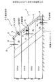
次に本発明によるダム施工用PC傾斜型枠とこのPC傾斜型枠を用いた施工方法が実際上どのように具体化されるか実施形態を説明する。図1は、本発明によるダム堤体の斜面施工方法を説明する縦断面図である。本発明の実施形態では、ダム堤体の内部には、CSGを採用している。通常のコンクリートダムは三角形の断面をしているが、台形断面とすることにより、コンクリートより品質は劣るがコストが安価なCSG(Cemented Sand and Gravel)を用いることができる。 Next, an embodiment of how the PC inclined mold for dam construction and the construction method using the PC inclined mold according to the present invention are actually realized will be described. FIG. 1 is a longitudinal sectional view explaining a slope construction method for a dam dam body according to the present invention. In the embodiment of the present invention, CSG is adopted inside the dam dam body. Ordinary concrete dams have a triangular cross section, but by using a trapezoidal cross section, it is possible to use CSG (Cemented Sand and Gravel), which is inferior to concrete but less expensive.
図1においては、まず最初のCSG1を1リフト分打設する。次いで、基礎コンクリート1上において、測量した所定の位置に、最初のPC傾斜型枠2を位置決めし据え付ける。このとき、基礎コンクリート1が硬化しないうちに、アンカーボルト3aを位置決めして挿入・埋設しておき、基礎コンクリート1が硬化してから、最初のPC傾斜型枠2を据え付ける。このとき、PC傾斜型枠2の台座版4に開けてあるボルト孔にアンカーボルト3aが入るように位置決めする。そして、ナット締めして、アンカーボルト3aにPC傾斜型枠2を固定してから、背部に保護遮水コンクリート5aを打設し、CSG1との間の空間を保護遮水コンクリート5aで埋める。
In FIG. 1, the
次に、前記のCSG1の上に、次の層のCSG2を打設した後、このCSG2と前記のPC傾斜型枠2との間に保護遮水コンクリート5bを打設する。このとき、保護遮水コンクリート5bの上面を水平に均すと共に、PC傾斜型枠2の頂端内面を基準にして、治具でアンカーボルト3bを位置決めして保護遮水コンクリート5b中に挿入して埋め込む。このとき、CSG3を打設しておく。そして、この保護遮水コンクリート5bが硬化してから、前記のアンカーボルト3bが台座版のボルト孔に入るように、第2段目のPC傾斜型枠2を据え付ける。そして、レベル調整手段6で水平度を調整し、アンカーボルトのナットを締めて台座版を固定してから、台座版の下にモルタルを流し込む。そして、CSG3と第2段目のPC傾斜型枠2との間の空間に保護遮水コンクリート5cを打設する。なお、PC傾斜型枠2の据え付けには、吊り金具7を利用してクレーンで吊り上げて位置決めするが、据え付け後には、吊り金具7を取り外すと共に、ボルト孔はモルタルで埋める。以上のように、CSGとPC傾斜型枠と保護遮水コンクリートを順次積層し施工していくという作業を繰り返すことによって、所要の高さまで斜面を形成していく。
Next, after the
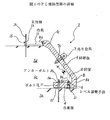
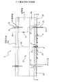
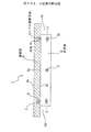
図2は、図1の第2段目のPC傾斜型枠2とその関連構成の詳細を示す図3B−B断面図であり、図2において右側が正面側であり、左側が背面側である。図3はPC傾斜型枠2の背面図(底版部のみ図4のC−C断面図)であり、図4は図3におけるA−A位置の断面図である。PC傾斜型枠2は、下端に形成した水平の平板状の台座版4と連続部8と平板状の斜壁版9とが一体にプレキャスト成型されている。前記の連続部8の正面側は鉛直面8aになっており、背面側は鉛直面8bになっている。また、斜壁版9の頂端9tの内面側9tbが鉛直面となっている。頂端9tの上面は水平面になっている。
FIG. 2 is a cross-sectional view of FIG. 3B-B showing details of the second-stage PC inclined
前記の斜壁版9の厚さは例えば10cmであり、台座版4の厚さは12cmである。また、連続部8の厚さは21cmであり、斜壁版9や台座版4より版厚を厚くすることによって、台座版4と斜壁版9との連続部8を強化すると共に、重量を大きくして、PC傾斜型枠全体の重心位置Wが台座版4の平面領域内に位置するように設定している。図示例の重心位置Wは、台座版内端から34cm、正面から21cmの位置に有る。そして、前記の吊り金具7は、クレーンなどで吊り上げた場合、重心位置Wが中心となるように吊り上げ可能な位置に着脱可能に装着してある。すなわち、図3の左右2箇所のボルト孔7h、7hからも明らかなように、左右2箇所に吊り金具7を取付けてあるが、この2箇所の吊り金具7・7を吊り上げた際に、丁度中間点9aが重心の位置と一致するようになっている。また、吊り金具7・7の高さ方向の位置は、吊り下げ孔が丁度、重心点Wの真上に来るように設定してある。なお、PC傾斜型枠2の左右方向すなわちスパン方向の寸法は、例えば299.5cmである。
The thickness of the slanted
前記のレベル調整手段6は、図4のように、台座版4において、前記の丁度中間点9aとスパン方向の両端付近に取付けてある。そして、中間位置のレベル調整手段6は台座版4の背面寄りに位置しているのに対し、両端のレベル調整手段6・6は、前記の厚肉の連続部8内に設けてある。すなわち、図2〜図4のように、レベル調整手段6を逃げるような凹室10を形成してある。そして、この凹室10中で、スパナなどを挿入して、レベル調整できる。以上のように、レベル調整手段6は、2等辺3角形上の3点に設けてあるので、PC傾斜型枠全体を正確にレベル調整できる。
As shown in FIG. 4, the level adjusting means 6 is attached to the
前記のアンカーボルト3bを挿入するボルト孔11は、前記の両端のレベル調整手段6・6の位置を背部に延長した位置に開けてある。上段のPC傾斜型枠の据え付けに際しては、その台座版4のボルト孔11中に、下段の保護遮水コンクリート5b中に埋め込み固定されているアンカーボルト3bが入るように位置合わせする。そして、該PC傾斜型枠のレベル調整などが完了した後は、アンカーボルト3bとボルト孔11との間の隙間にモルタルを充填してからナット3Nで締めつけ固定する。
The bolt holes 11 into which the
前記のように、アンカーボルトに合わせてPC傾斜型枠を位置決めするので、アンカーボルトを埋め込み固定する際には、その設置位置を正確に位置決めする必要がある。図2、図3では、このようにアンカーボルトの位置を決定する治具12が斜壁版9の頂端内面9tbに取付けられている。この治具12の他端には、アンカーボルトを挿入支持する支持筒13を固定してあるので、保護遮水コンクリート5dが硬化しないうちに、支持筒13中にアンカーボルト3cを挿通し、下側の保護遮水コンクリート5d中に差し込んで埋め込むと、斜壁版の頂端内面9tbを基準とした正確な位置にアンカーボルト3cが設置されたことになる。そして、保護遮水コンクリート5dが硬化してから、治具12を取り外し、アンカーボルト3cを利用して、次の段のPC傾斜型枠を据え付ける。なお、アンカーボルト3cをセットした後に、下側の保護遮水コンクリート5dを打設してもよい。
As described above, the PC inclined mold is positioned in accordance with the anchor bolt. Therefore, when the anchor bolt is embedded and fixed, it is necessary to accurately position the installation position. 2 and 3, the
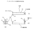
図5は治具12の詳細を示す図で、(1)は平面図、(2)は側面図、(3)は正面図である。この治具12は、水平方向に延びたC型鋼からなる連結部材12jの一端に、PC傾斜型枠の斜壁版9の頂端9tの鉛直の内面側9tbに仮止め固定する基準板14を鉛直状態に固定してある。また、他端上には、アンカーボルトを挿入支持する支持筒13を鉛直状態に立てて固定してある。そして、この支持筒13には、内部に挿入されているアンカーボルトを固定するために、蝶ボルト15を螺合させてある。
FIG. 5 is a diagram showing details of the
この治具12の使用に際しては、図2の保護遮水コンクリート5dの打設後に、PC傾斜型枠の斜壁版9の頂端9tの鉛直面9tbに基準板14をボルト孔16を利用してボルト止めする。そして、他端の支持筒13の中にアンカーボルト3cを挿通すると共に下段の保護遮水コンクリート5d中に打ち込んで埋設すると、前記の斜壁版鉛直面9tbから一定の位置にアンカーボルト3cが設置されたことになる。そして、下段の保護遮水コンクリート5dが硬化してから、治具12を取り外して、上段のPC傾斜型枠を据え付ける。
When the
このPC傾斜型枠の据え付け方を図2のPC傾斜型枠2について説明すると、まずレベル調整手段6の下に鉄板21を敷いた状態で、レベル調整する。図示のレベル調整手段6は、台座版4中にメネジ筒を埋め込んだ構成になっているので、このメネジ筒に螺合させたレベル調整ボルト6bを回転操作することによって、台座版4を上下させてレベル調整できる。レベル調整の後、アンカーボルトをナット締めして固定してから、台座版4の下の隙間にモルタル22を流し込んで充填する。その後、CSG部との間に保護遮水コンクリート5c、5dを打設するが、各PC傾斜型枠の連続部8の正面が、治具の取付け基準面となった、下段のPC傾斜型枠の頂端内面9tbの背部に位置するように、アンカーボルトで位置決めされているため、背部の保護遮水コンクリートを打設する際の保護遮水コンクリートの圧力によって、PC傾斜型枠が正面側に押し出されるのを防止するストッパーの役目も頂端内面9tbが兼ねることになり、位置精度の高いPC傾斜型枠式堤体が実現できる。
Referring to the PC inclined
こうして、PC傾斜型枠2の背部に保護遮水コンクリートを打設した際に、PC傾斜型枠2と保護遮水コンクリートとが確実に密着して一体化されるように、斜壁版9の背面は予め粗面化されている。粗面化する手法は任意でよいが、例えば、斜壁版背面に圧力水をジェット噴射したり、サンドブラストする。
Thus, when the protective water-impervious concrete is placed on the back of the PC inclined
また、ダム堤体などにおいては、多数のPC傾斜型枠を水平方向に並べて据え付けるが、隣接するPC傾斜型枠間の隙間から水漏れしたり、保護遮水コンクリートを打設する際にのろが漏れ出すのを防ぐことが望ましい。そのため、据え付け状態において、図7のように、隣接するPC傾斜型枠C1、C2の隣接する斜壁版の内面に渡って遮水性のテープ20を貼ることが望ましい。すなわち、隣接する斜壁版間の隙間の上に遮水性のテープ20を貼り付けておいてから、保護遮水コンクリートを打設する。 In addition, on dam dams, etc., a large number of PC inclined molds are installed side by side in the horizontal direction, but when leaking from the gaps between adjacent PC inclined molds or when placing protective impermeable concrete, It is desirable to prevent leakage. Therefore, in the installed state, as shown in FIG. 7, it is desirable to apply a water-blocking tape 20 over the inner surfaces of the adjacent slant wall plates of the adjacent PC inclined molds C1 and C2. That is, after the water-impervious tape 20 is stuck on the gap between the adjacent slant wall plates, the protective water-impervious concrete is placed.
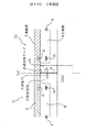
図6は止水板の設置方法を示す図で、図7のG12位置の縦断面図である。図7は図6のD−D断面図であり、保護遮水コンクリートの目地切りの位置を塞ぐための止水板17を設けてある。大規模なコンクリート構造体の場合、コンクリートの温度応力や経時変化に伴うひび割れは避けられない。そこで、コンクリート打設時に約15m間隔で目地切りをしておいて、目地切り部分で、寸法変化を吸収させることが一般に行われている。本発明における保護遮水コンクリートの場合は、この目地切りを、隣接するPC傾斜型枠の境界の位置で行なっている。 FIG. 6 is a view showing a method for installing a water stop plate, and is a longitudinal sectional view at a position G12 in FIG. FIG. 7 is a cross-sectional view taken along the line DD of FIG. 6 and is provided with a water stop plate 17 for closing the joint cutting position of the protective water-impervious concrete. In the case of a large-scale concrete structure, cracks due to temperature stress and aging of the concrete are inevitable. Therefore, it is generally performed that joints are cut at intervals of about 15 m at the time of placing concrete and the dimensional change is absorbed at the joints. In the case of the protective water-impervious concrete in the present invention, this joint cutting is performed at the position of the boundary between adjacent PC inclined molds.
すなわち、図7のように、約15m位置で隣接するPC傾斜型枠C1、C2の隣接する位置G12で目地切りを行なう。目地切りのために、止水板17とCSG部との間に立てる支持鉄板2aを準備し、さらに止水板17と斜壁版9との間に立てる支持鉄板1aとを用意しておく。そして、斜壁版9を設置した後に、前記のCSG部側の支持鉄板2aと斜壁版9側の支持鉄板1aを立てて、間に止水板17を挟持する。この状態で、CSG部と止水板17と支持鉄板2a、1aとPC傾斜型枠C1・C2との間の空間に保護遮水コンクリートを打設することによって、図1に示す保護遮水コンクリート5a、5bを形成する。
That is, as shown in FIG. 7, joint cutting is performed at the adjacent position G12 of the PC inclined molds C1 and C2 which are adjacent at a position of about 15 m. For joint cutting, a supporting
そして養生後に、上段のPC傾斜型枠C1、C2を設置した後、前記と同様にCSG部側の支持鉄板2aと斜壁版9側の支持鉄板1aを立てて、間に止水板17を挟持してから、CSG部と止水板17と支持鉄板2a、1aとPC傾斜型枠C1・C2との間の空間に保護遮水コンクリートを打設する。このようにして、下側の段から上側の段に順次延ばして来た止水板17を目地切り位置に埋め込んでいく。
After curing, after installing the upper PC inclined molds C1 and C2, the
このように、目地切りした箇所では、水漏れ防止のために止水板17を設けるため、止水板17の全長にわたって所定寸法のコンクリート被りを確保する必要がある。ところが、PC傾斜型枠の台座版4の端部が止水板17の設置の邪魔になるので、止水板17から被り寸法分を確保できるように、止水板17を避けるために、台座版端部に欠除空間191、192を形成してある。そして、この欠除空間191、192中で止水板17を位置決めしてから、この欠除空間191、192中にも保護遮水コンクリートを打設するので、所要寸法の被りを確保して、水漏れ防止を確保できる。このように被り確保の目的で欠除空間191、192を形成しているが、各PC傾斜型枠2の両端に欠除空間191、192を形成することによって、PC傾斜型枠自体の軽量化と材料費節減となる。なお、20は、前記の隣接斜壁版間に貼る遮水性テープである。
As described above, in order to provide the water stop plate 17 in order to prevent water leakage at the jointed portion, it is necessary to secure a concrete covering having a predetermined dimension over the entire length of the water stop plate 17. However, since the end portion of the
以上のように、本発明によると、台座版と一体に連続している斜壁版を有する自立型のPC傾斜型枠を使用し、下段のCSG部とPC傾斜型枠との間に打設した保護遮水コンクリート中に、下段のPC傾斜型枠の斜壁版の頂端内面の鉛直面を基準にして、治具で位置決めしてアンカーボルトを挿入埋め込みして、上段のPC傾斜型枠の据え付けの基準にする。そして、保護遮水コンクリートが硬化した後に、前記の治具を除去して、前記のアンカーボルトが上段のPC傾斜型枠の台座版のアンカーボルト孔に入るように位置決めして固定してから、上段のPC傾斜型枠とCSG部との間に保護遮水コンクリートを打設する。このように自立型のPC傾斜型枠を用いるので、作業が容易で能率的に施工でき、工期の短縮が可能となる。PC傾斜型枠の据え付けも容易で正確となり、水漏れ防止なども万全である。 As described above, according to the present invention, a self-supporting PC inclined mold having a slanted wall slab that is continuous with the pedestal is used, and placed between the lower CSG portion and the PC inclined mold. In the protected water-impervious concrete, the vertical surface of the top end of the slant wall plate of the lower PC inclined mold frame is used as a reference, and the anchor bolt is inserted and embedded with the jig, and the upper PC inclined mold frame Use as a standard for installation. Then, after the protective impermeable concrete is cured, the jig is removed, and the anchor bolt is positioned and fixed so that the anchor bolt enters the anchor bolt hole of the pedestal plate of the upper PC inclined mold frame. Protective impermeable concrete is placed between the upper PC inclined formwork and the CSG part. As described above, since the self-supporting PC inclined formwork is used, the work can be performed easily and efficiently, and the construction period can be shortened. PC inclined formwork can be installed easily and accurately, and water leak prevention is also perfect.
1 基礎コンクリート
2 PC傾斜型枠
3 アンカーボルト
4 台座版
5 保護遮水コンクリート(後打ちコンクリート)
6 レベル調整手段
7 吊り金具
8 連続部
9 斜壁版
9tb 頂端内面
W 重心点
10 凹室
11 ボルト孔
12 治具
12j 連結部材
13 支持筒
14 基準板
15 蝶ボルト
16 ボルト孔
17 止水板
191、192 欠除空間
20 遮水性テープ
1 Foundation concrete
2 PC inclined formwork
3 Anchor bolt
4 pedestal version
5 Protective impermeable concrete (post-cast concrete)
6 Level adjustment means
7 Hanging bracket
8 continuous parts
9 Diagonal wall version
9tb Top end inner surface
W Center of gravity
DESCRIPTION OF
Claims (10)
水平の台座版と一体の斜壁版を有し、
前記台座版と斜壁版との連続部正面に鉛直面を有し、
前記斜壁版の頂端背面にも鉛直面を有していて、
下段の斜壁版の頂端背面の鉛直面の背部に、上段の台座版正面の鉛直面が配置される構造となっていることを特徴とするPC傾斜型枠。 It is a PC inclined form used when constructing slopes such as dam dam bodies,
It has a slant wall plate integrated with a horizontal pedestal plate,
Having a vertical surface in front of the continuous part of the pedestal plate and the inclined wall plate,
It also has a vertical surface on the back of the top end of the inclined wall plate,
A PC inclined formwork characterized in that a vertical surface in front of the upper pedestal plate is arranged on the back of the vertical surface on the back of the top end of the lower inclined wall plate.
前記台座版と斜壁版との連続部の背面にも鉛直面を形成してあり、この背面の鉛直面と前記の連続部正面の鉛直面との間の版厚を、前記の斜壁版および台座版の版厚より大きくしてあることを特徴とする請求項1に記載のPC傾斜型枠。 In the plane area of the pedestal plate, the center of gravity of the entire PC inclined mold is located,
A vertical surface is also formed on the back surface of the continuous portion of the pedestal plate and the inclined wall plate, and the plate thickness between the vertical surface of the back surface and the vertical surface of the continuous portion front is determined by the inclined wall plate. The PC inclined mold according to claim 1, wherein the PC inclined mold is larger than the plate thickness of the base plate.
前記PC傾斜型枠の重心位置を吊り上げ可能な位置に、着脱可能な吊り金具を仮止め可能となっていることを特徴とする請求項1または請求項2に記載のPC傾斜型枠。 In the above slanted wall version,
The PC inclined mold according to claim 1 or 2, wherein a detachable hanging bracket can be temporarily fixed at a position where the center of gravity of the PC inclined mold can be lifted.
アンカーボルト挿入孔を開けてあり、
しかも、スパン方向の両端と中間部に、レベル調整手段を装備してあることを特徴とするPC傾斜型枠。 In the horizontal pedestal version of PC inclined formwork,
There is an anchor bolt insertion hole,
Moreover, the PC inclined mold is characterized in that level adjusting means are provided at both ends and an intermediate portion in the span direction.
水平方向に延びた連結部材の一端に、PC傾斜型枠の斜壁版の頂端背面の鉛直面に仮止め固定する基準部材を有しており、
他端には、アンカーボルトを挿入支持する位置決め孔を有していることを特徴とする位置決め治具。 A jig for determining the anchor bolt fixing position,
At one end of the connecting member extending in the horizontal direction, it has a reference member that is temporarily fixed to the vertical surface of the top end of the inclined wall plate of the PC inclined mold frame,
A positioning jig having a positioning hole for inserting and supporting an anchor bolt at the other end.
CSG部と自立させて据え付けしたPC傾斜型枠との間の空間部に、後打ちコンクリートとして保護遮水コンクリートを打設してなる構造を、複数段積層施工してなることを特徴とする斜面構造。 It is a construction structure of a slope such as a dam body,
A slope formed by laminating multiple layers of a structure in which protective water-impervious concrete is cast as post-cast concrete in the space between the CSG section and the PC inclined mold that is installed independently. Construction.
隣接するPC傾斜型枠の隣接する前記斜壁版において、少なくとも斜壁版の内面に、隣接するPC傾斜型枠間の隙間をシールするための遮水性のテープを貼ってあることを特徴とする請求項9に記載の斜面構造。 The PC inclined mold has a slant wall plate integrated with a horizontal pedestal plate,
In the adjacent inclined wall plate of the adjacent PC inclined mold, a water shielding tape for sealing a gap between adjacent PC inclined molds is pasted at least on the inner surface of the inclined wall plate. The slope structure according to claim 9.
前記の保護遮水コンクリートが硬化した後に、前記の治具を除去して、前記のアンカーボルトが上段のPC傾斜型枠の台座版のアンカーボルト孔に入るように位置決めして固定してから、
上段のPC傾斜型枠とCSG部との間に保護遮水コンクリートを打設することを特徴とするPC傾斜型枠を用いた斜面部の施工方法。 Positioning in protective water-impervious concrete placed between the lower CSG section and the PC inclined formwork using a jig with reference to the vertical surface of the top end inner surface of the inclined wall plate of the lower PC inclined formwork With the anchor bolt inserted,
After the protective impermeable concrete is cured, the jig is removed, and the anchor bolt is positioned and fixed so that the anchor bolt enters the anchor bolt hole of the pedestal plate of the upper PC inclined mold frame.
A method for constructing a slope portion using a PC inclined mold frame, characterized in that protective water-impervious concrete is placed between the upper PC inclined mold frame and the CSG portion.
Priority Applications (1)
| Application Number | Priority Date | Filing Date | Title |
|---|---|---|---|
| JP2004106767A JP4079435B2 (en) | 2004-03-31 | 2004-03-31 | Construction method of PC inclined formwork and dam body for dam construction |
Applications Claiming Priority (1)
| Application Number | Priority Date | Filing Date | Title |
|---|---|---|---|
| JP2004106767A JP4079435B2 (en) | 2004-03-31 | 2004-03-31 | Construction method of PC inclined formwork and dam body for dam construction |
Publications (2)
| Publication Number | Publication Date |
|---|---|
| JP2005290818A true JP2005290818A (en) | 2005-10-20 |
| JP4079435B2 JP4079435B2 (en) | 2008-04-23 |
Family
ID=35324065
Family Applications (1)
| Application Number | Title | Priority Date | Filing Date |
|---|---|---|---|
| JP2004106767A Expired - Lifetime JP4079435B2 (en) | 2004-03-31 | 2004-03-31 | Construction method of PC inclined formwork and dam body for dam construction |
Country Status (1)
| Country | Link |
|---|---|
| JP (1) | JP4079435B2 (en) |
Cited By (5)
| Publication number | Priority date | Publication date | Assignee | Title |
|---|---|---|---|---|
| JP2008081961A (en) * | 2006-09-26 | 2008-04-10 | Dam Gijutsu Center | Concrete dam construction method |
| JP2008214914A (en) * | 2007-03-01 | 2008-09-18 | Dam Gijutsu Center | Construction method of trapezoidal CSG dam |
| CN104695455A (en) * | 2015-03-06 | 2015-06-10 | 华能澜沧江水电股份有限公司 | High-flow and high-head antiscour and anti-seepage overflow cofferdam structure and construction method thereof |
| CN111979973A (en) * | 2020-07-23 | 2020-11-24 | 中国电建集团华东勘测设计研究院有限公司 | Method for rapidly constructing slag dam of abandoned slag yard and slag dam of abandoned slag yard |
| JP2022035289A (en) * | 2020-08-20 | 2022-03-04 | 鹿島建設株式会社 | Displacement measuring method and construction method of concrete dam body |
-
2004
- 2004-03-31 JP JP2004106767A patent/JP4079435B2/en not_active Expired - Lifetime
Cited By (6)
| Publication number | Priority date | Publication date | Assignee | Title |
|---|---|---|---|---|
| JP2008081961A (en) * | 2006-09-26 | 2008-04-10 | Dam Gijutsu Center | Concrete dam construction method |
| JP2008214914A (en) * | 2007-03-01 | 2008-09-18 | Dam Gijutsu Center | Construction method of trapezoidal CSG dam |
| CN104695455A (en) * | 2015-03-06 | 2015-06-10 | 华能澜沧江水电股份有限公司 | High-flow and high-head antiscour and anti-seepage overflow cofferdam structure and construction method thereof |
| CN111979973A (en) * | 2020-07-23 | 2020-11-24 | 中国电建集团华东勘测设计研究院有限公司 | Method for rapidly constructing slag dam of abandoned slag yard and slag dam of abandoned slag yard |
| JP2022035289A (en) * | 2020-08-20 | 2022-03-04 | 鹿島建設株式会社 | Displacement measuring method and construction method of concrete dam body |
| JP7407088B2 (en) | 2020-08-20 | 2023-12-28 | 鹿島建設株式会社 | Displacement measurement method and construction method for concrete embankment body |
Also Published As
| Publication number | Publication date |
|---|---|
| JP4079435B2 (en) | 2008-04-23 |
Similar Documents
| Publication | Publication Date | Title |
|---|---|---|
| KR101588593B1 (en) | Temporary bridge construction method | |
| KR20140047118A (en) | Foundation system for bridges | |
| US20120047822A1 (en) | Earthquake force absorption system | |
| CN112814235B (en) | Construction method of layered diversion open type stone curtain wall | |
| CN108797638A (en) | Integrated assembled piping lane based on composite bottom board and its construction method | |
| CN102226345B (en) | Method for carrying out advanced water shut-off on post-cast strips in underground engineering and advanced water shut-off steel plate structure | |
| JP2018112009A (en) | Vertical member installation structure, vertical member installation method, and precast vertical member | |
| JP2014080824A (en) | Method for constructing foundation structure by utilizing skeleton of existing structure, and foundation structure | |
| JP4079435B2 (en) | Construction method of PC inclined formwork and dam body for dam construction | |
| JP2008274612A (en) | Overhang railing structure and overhang railing method | |
| JP4448066B2 (en) | Flexible waterproof joint and its construction method | |
| JP6039186B2 (en) | Wall railing formwork | |
| CN114017058A (en) | Construction method of fabricated air duct partition plate for plateau railway tunnel double-lane trackless transportation auxiliary gallery | |
| CN217630116U (en) | Front-mounted assembly type water-stop post-pouring belt | |
| CN217419302U (en) | Assembled modulus formula bridge expansion joint | |
| JP2017193857A (en) | Attachment structure of transverse member and guard fence | |
| JP3663594B2 (en) | Method for constructing handrail of dam body and precast concrete handrail for dam body | |
| JP7488044B2 (en) | Movable platform fence installation structure and movable platform fence installation method | |
| CN120311861B (en) | Prefabricated building stacked structure and construction method thereof | |
| CN222936314U (en) | A pre-buried rail and cornice support system for river dams | |
| JP2811139B2 (en) | Formwork for dam body and method of constructing dam body using this formwork | |
| JP2000129953A (en) | Fitting method of base isolation device to foundation | |
| CN215717719U (en) | Aluminum alloy wall template bottom leak protection thick liquid device | |
| JP5761701B1 (en) | How to repair the wall that raises the observer passage in the tunnel | |
| JP3369436B2 (en) | Piping construction method |
Legal Events
| Date | Code | Title | Description |
|---|---|---|---|
| A621 | Written request for application examination |
Free format text: JAPANESE INTERMEDIATE CODE: A621 Effective date: 20051115 |
|
| A977 | Report on retrieval |
Free format text: JAPANESE INTERMEDIATE CODE: A971007 Effective date: 20070418 |
|
| A131 | Notification of reasons for refusal |
Free format text: JAPANESE INTERMEDIATE CODE: A131 Effective date: 20070508 |
|
| A521 | Request for written amendment filed |
Free format text: JAPANESE INTERMEDIATE CODE: A523 Effective date: 20070709 |
|
| A131 | Notification of reasons for refusal |
Free format text: JAPANESE INTERMEDIATE CODE: A131 Effective date: 20071002 |
|
| A521 | Request for written amendment filed |
Free format text: JAPANESE INTERMEDIATE CODE: A523 Effective date: 20071018 |
|
| TRDD | Decision of grant or rejection written | ||
| A01 | Written decision to grant a patent or to grant a registration (utility model) |
Free format text: JAPANESE INTERMEDIATE CODE: A01 Effective date: 20071211 |
|
| A601 | Written request for extension of time |
Free format text: JAPANESE INTERMEDIATE CODE: A601 Effective date: 20071218 |
|
| A602 | Written permission of extension of time |
Free format text: JAPANESE INTERMEDIATE CODE: A602 Effective date: 20071221 |
|
| A61 | First payment of annual fees (during grant procedure) |
Free format text: JAPANESE INTERMEDIATE CODE: A61 Effective date: 20080204 |
|
| FPAY | Renewal fee payment (event date is renewal date of database) |
Free format text: PAYMENT UNTIL: 20110215 Year of fee payment: 3 |
|
| R150 | Certificate of patent or registration of utility model |
Ref document number: 4079435 Country of ref document: JP Free format text: JAPANESE INTERMEDIATE CODE: R150 Free format text: JAPANESE INTERMEDIATE CODE: R150 |
|
| A521 | Request for written amendment filed |
Free format text: JAPANESE INTERMEDIATE CODE: A821 Effective date: 20080204 |
|
| FPAY | Renewal fee payment (event date is renewal date of database) |
Free format text: PAYMENT UNTIL: 20110215 Year of fee payment: 3 |
|
| S531 | Written request for registration of change of domicile |
Free format text: JAPANESE INTERMEDIATE CODE: R313531 |
|
| FPAY | Renewal fee payment (event date is renewal date of database) |
Free format text: PAYMENT UNTIL: 20110215 Year of fee payment: 3 |
|
| R350 | Written notification of registration of transfer |
Free format text: JAPANESE INTERMEDIATE CODE: R350 |
|
| FPAY | Renewal fee payment (event date is renewal date of database) |
Free format text: PAYMENT UNTIL: 20110215 Year of fee payment: 3 |
|
| S531 | Written request for registration of change of domicile |
Free format text: JAPANESE INTERMEDIATE CODE: R313531 |
|
| FPAY | Renewal fee payment (event date is renewal date of database) |
Free format text: PAYMENT UNTIL: 20110215 Year of fee payment: 3 |
|
| R350 | Written notification of registration of transfer |
Free format text: JAPANESE INTERMEDIATE CODE: R350 |
|
| FPAY | Renewal fee payment (event date is renewal date of database) |
Free format text: PAYMENT UNTIL: 20110215 Year of fee payment: 3 |
|
| FPAY | Renewal fee payment (event date is renewal date of database) |
Free format text: PAYMENT UNTIL: 20110215 Year of fee payment: 3 |
|
| FPAY | Renewal fee payment (event date is renewal date of database) |
Free format text: PAYMENT UNTIL: 20140215 Year of fee payment: 6 |
|
| R250 | Receipt of annual fees |
Free format text: JAPANESE INTERMEDIATE CODE: R250 |
|
| FPAY | Renewal fee payment (event date is renewal date of database) |
Free format text: PAYMENT UNTIL: 20140215 Year of fee payment: 6 |
|
| S533 | Written request for registration of change of name |
Free format text: JAPANESE INTERMEDIATE CODE: R313533 |
|
| R350 | Written notification of registration of transfer |
Free format text: JAPANESE INTERMEDIATE CODE: R350 |
|
| R250 | Receipt of annual fees |
Free format text: JAPANESE INTERMEDIATE CODE: R250 |
|
| S111 | Request for change of ownership or part of ownership |
Free format text: JAPANESE INTERMEDIATE CODE: R313117 |
|
| S531 | Written request for registration of change of domicile |
Free format text: JAPANESE INTERMEDIATE CODE: R313532 |
|
| R350 | Written notification of registration of transfer |
Free format text: JAPANESE INTERMEDIATE CODE: R350 |
|
| EXPY | Cancellation because of completion of term |