JP2005290775A - Trowel for plasterer - Google Patents
Trowel for plasterer Download PDFInfo
- Publication number
- JP2005290775A JP2005290775A JP2004105787A JP2004105787A JP2005290775A JP 2005290775 A JP2005290775 A JP 2005290775A JP 2004105787 A JP2004105787 A JP 2004105787A JP 2004105787 A JP2004105787 A JP 2004105787A JP 2005290775 A JP2005290775 A JP 2005290775A
- Authority
- JP
- Japan
- Prior art keywords
- back metal
- plasterer
- plate
- trowel
- cut
- Prior art date
- Legal status (The legal status is an assumption and is not a legal conclusion. Google has not performed a legal analysis and makes no representation as to the accuracy of the status listed.)
- Granted
Links
- 239000002184 metal Substances 0.000 claims abstract description 49
- 229910052751 metal Inorganic materials 0.000 claims abstract description 49
- 239000000853 adhesive Substances 0.000 claims abstract description 9
- 230000001070 adhesive effect Effects 0.000 claims abstract description 9
- 230000000149 penetrating effect Effects 0.000 claims description 5
- 101100008050 Caenorhabditis elegans cut-6 gene Proteins 0.000 abstract description 2
- 238000005452 bending Methods 0.000 description 11
- XEEYBQQBJWHFJM-UHFFFAOYSA-N Iron Chemical compound [Fe] XEEYBQQBJWHFJM-UHFFFAOYSA-N 0.000 description 2
- 229910000831 Steel Inorganic materials 0.000 description 2
- 238000004519 manufacturing process Methods 0.000 description 2
- 239000011505 plaster Substances 0.000 description 2
- 239000010959 steel Substances 0.000 description 2
- 238000005553 drilling Methods 0.000 description 1
- 238000010438 heat treatment Methods 0.000 description 1
- 229910052742 iron Inorganic materials 0.000 description 1
- 238000000034 method Methods 0.000 description 1
- 239000002893 slag Substances 0.000 description 1
- 229910001220 stainless steel Inorganic materials 0.000 description 1
- 239000010935 stainless steel Substances 0.000 description 1
Images
Landscapes
- Finishing Walls (AREA)
Abstract
Description
本発明は、左官鏝の改良に関するものであり、さらに詳しくは、薄い鋼板からなる鏝板の上面中央に弾性金属で作られた背板を取着した左官鏝に関するものである。 The present invention relates to improvement of a plasterer, and more particularly to a plasterer in which a back plate made of an elastic metal is attached to the center of the upper surface of a thin plate made of a thin steel plate.
従来より、この種の左官鏝(しごき鏝と称される)として、弾性金属で作られた背金の上に柱脚を立設し、柱脚より前端部及び後端部に掛けて漸進的に背金の厚さを薄くしたことによって背金端部を撓み易くし、この背金を鏝板に弾性変形可能な接着剤を使用して接着し、鏝使用時に鏝板の撓みに背金も追随して撓むようにした構成の鏝が提案されている。(例えば、特許文献1参照)。 Conventionally, as this kind of plasterer (referred to as a slag iron), a column base is erected on a back metal made of an elastic metal and is gradually extended from the column base to the front end and the rear end. The thickness of the back metal is reduced to make the end of the back metal easier to bend, and this back metal is bonded to the base plate using an elastically deformable adhesive. However, there has been proposed a bag having a configuration that bends and follows. (For example, refer to Patent Document 1).
しかし、前記するように、背金の中間部から両端部に掛けて漸進的に厚みを薄くする場合は、普通、背金の表面を切削加工によって薄くしていくので、背金の加工に手間が掛かるばかりでなく、切削加工時の熱的歪みも生じ易いもので、背金の品質性能を一定にすることが難しいものである。
本発明は、このような状況に鑑みてなされたものであって、左官鏝の背金の厚みはそのままに、背金に対する簡単な加工によって必要とされる背金の撓り度が簡単に得られて、使い勝手のよい高品質の左官鏝を安価に供給することを目的としたものである。 The present invention has been made in view of such a situation. The thickness of the back metal of the plasterer is kept as it is, and the bending degree of the back metal required by simple processing on the back metal can be easily obtained. The purpose is to provide an easy-to-use high-quality plasterer at low cost.
上記の目的を達成するための本発明に係る左官鏝は、鏝板の上面中央に、柱脚を立設した背金を接着剤を介して取着した左官鏝において、背金の前端から適宜の範囲で、板面を貫通する切り込みを面的拡がりを以て設けたことを特徴とする。 To achieve the above object, a plasterer according to the present invention is a plasterer in which a back metal provided with a column base is attached to the center of the top surface of the base plate through an adhesive. In this range, the slits penetrating the plate surface are provided with a surface expansion.
このように構成した本発明の左官鏝によれば、鏝を使用するに当たって、鏝板の尾端を持ち上げて鏝板先端部で壁面を押さえ付けるような時に、鏝板の先端部が曲げられて鏝板が撓るのに伴い、鏝板と一体に背金も適切に撓みを生じる結果、鏝板の撓りが良くなって使い勝手の良い左官鏝が得られて作業性を向上できる。 According to the plasterer of the present invention configured as described above, when using the coffin, when the tail end of the coffin plate is lifted and the wall surface is pressed by the coffin plate tip, the front end portion of the coffin plate is bent. As the base plate is bent, the back metal is also appropriately bent integrally with the base plate. As a result, the base plate is flexed and an easy-to-use plasterer is obtained, thereby improving workability.
また、前記構成において、背金の板面を貫通して切り込みを設けるのは、外部から背金の先端部に掛かる曲げ力に対し、背金の板体強度を低下させて撓り易くするためのものである。 Further, in the above-mentioned configuration, the notch is provided through the plate surface of the back metal in order to reduce the strength of the plate body of the back metal and make it easy to bend with respect to the bending force applied to the tip of the back metal from the outside. belongs to.
そこで、背金の先端部に設ける切込みの具体例としては、整列状に設けた複数の穿孔で形成することができる。この場合の穿孔は汎用のドリルを使用しての穿孔加工ができるので、作業が簡単で生産コストの低減が図られる。 Therefore, as a specific example of the cut provided at the tip of the back metal, it can be formed by a plurality of perforations provided in an aligned manner. Since the drilling in this case can be performed using a general-purpose drill, the operation is simple and the production cost can be reduced.
また、背金の先端部に設ける切込みの別の具体例としては、レーザー加工等による線状の連続切れ目で形成することができる。この場合の線状の連続切れ目を、背金幅方向及び長手方向に拡がりを持ち、屈曲して連続する線状切り込みにすると、背金に対する線状切れ目の入れ方によって、背金と鏝板が一体で所定の撓り度が得られるようにできる。 As another specific example of the cut provided at the tip of the back metal, it can be formed by a linear continuous cut by laser processing or the like. In this case, when the linear continuous cut extends in the width direction and the longitudinal direction of the back metal and is bent into a continuous linear cut, the back metal and the base plate are separated depending on how the linear cut is made with respect to the back metal. A predetermined degree of bending can be obtained integrally.
本発明によれば、作業上から鏝板の撓りが求められる左官鏝において、鏝板上の背金前端部に対する簡単な加工で、鏝板と一体に背金も適切に撓みを生じて鏝板の撓りを良くすることができるので、使い勝手の良い左官鏝が得られて作業性を向上できる。また、背金の前端部の加工には、汎用の装置を使用して簡単な加工で済むので、生産コストの低減が図られ、しかも、熱的歪み等を生じることがないので、品質性能を一定にする高品質の左官鏝が提供できる。 According to the present invention, in a plasterer that requires the bending of the cover plate from the viewpoint of work, the back plate is also appropriately bent integrally with the cover plate by a simple process on the front end portion of the back plate on the cover plate. Since the bending of the plate can be improved, an easy-to-use plasterer can be obtained and workability can be improved. In addition, the processing of the front end of the back metal can be done simply by using a general-purpose device, so that the production cost can be reduced and the thermal performance is not caused. High quality plasterer can be provided.
以下、図面を参照しながら、本発明の実施例に係る左官鏝について具体的に説明する。 Hereinafter, a plasterer according to an embodiment of the present invention will be specifically described with reference to the drawings.
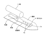
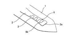
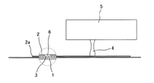
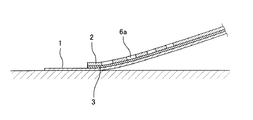
図1は本発明に係る左官鏝の斜視図、図2は鏝板の一部分を示す斜視図、図3は要部を拡大して断面で示した左官鏝の側面図、図4は鏝板の撓り具合を示す断面図である。 FIG. 1 is a perspective view of a plasterer according to the present invention, FIG. 2 is a perspective view showing a part of a plaster board, FIG. 3 is a side view of the plasterer with a main portion enlarged, and FIG. It is sectional drawing which shows a bending condition.
図1に示すように、鏝板1は弾性のある薄い金属板、例えば、厚さ0.5〜1mm程度の鋼板またはステンレス鋼板からなるもので、形状としては、鏝の用途によって矩形又は先端をV状等に形成したものである。
As shown in FIG. 1, the
鏝板1の上面中央には、その長手方向に細長く短冊状をなす背金2が接着剤3を介して取着されている。この背金2には、その中央部よりやや後方に寄せた位置に柱脚4を立設しており、この柱脚4には木製の柄5を取着している。
A
前記する鏝板1と背金2は接着剤3で接着され、両者間に存在する接着剤3層は、作業現場で左官鏝が使用されて鏝板1と背金2が共に撓る際に、両者の曲率半径の違いから生じる不整合を接着剤3層が弾性変形して吸収するものである。なお、前記する左官鏝の基本構成は、周知のものである。
The
本発明に係る左官鏝の背金2には、背金2の前端2aから適宜の範囲で、板面を貫通する切り込み6が面的拡がりを以て設けられており、鏝板1の先端部の撓りに対して背金2の先端部も無理なく撓みを追従させるようにしている。
The
背金2の先端部に設ける切り込み6の具体例としては、図1に示すように、背金2に明けられた穿孔6aであっても良いし、図2に示すように、レーザー加工等によって板面を貫通させた線状の切れ目6bであっても良い。何れにしても、背金2の板面を貫通して切り込み6を設けたことによって、外部から背金2の先端部に掛かる曲げ力に対して板体強度を低下させて撓り易くしたものである。
As a specific example of the
また、図1に示すように、穿孔6aによって板面強度を低下させる場合は、穿孔部分の板面強度は孔径に比例するので、大きな撓り度が求められる背金2の先端側から段階的に穴径を小さくした複数の穿孔6aを整列状に設け、背金2と鏝板1が一体で所定の撓り度が得られるようにしている。また、図2に示すように、板面を貫通させた線状の切れ目6bである場合は、所定の間隔で背金幅方向に延びる直線部と背金長手方向で隣り合う直線部の両端部間を円弧線で連続させた線状切り込みとし、背金2に対する線状切れ目6bの入れ方によって、背金2と鏝板1が一体で所定の撓り度が得られるようにしている。
Further, as shown in FIG. 1, when the plate surface strength is reduced by the
而して、上記構成からなる本発明の左官鏝によれば、図4に示すように、鏝を使用するに当たって、鏝板の尾端を持ち上げて鏝板1の先端部で壁面を押さえ付けると、鏝板1の先端部が曲げられて鏝板1が撓るのに伴い、鏝板1と一体に、複数の穿孔6aを整列状に設けた背金2も適切に撓みを生じて左官鏝の使い勝手を良くするものである。
Thus, according to the plasterer of the present invention having the above-described structure, as shown in FIG. 4, when using the scissors, if the tail end of the scissors is lifted and the wall surface is pressed by the tip of the
本発明に係る左官鏝は種類も多いものであるが、本発明に係るような左官鏝によれば、構造が簡単で左官鏝の使い勝手を格段に向上できるので、その利用範囲は極めて広範になり、販売範囲を拡大して販売増強を図ることができる実用上、極めて有益なものである。 There are many types of plasterers according to the present invention. However, according to the plasterer according to the present invention, the structure is simple and the usability of the plasterer can be greatly improved. It is extremely useful in practical use that can expand sales range and increase sales.
1 鏝板
2 背金
2a 前端
3 接着剤
4 柱脚
5 柄
6 切り込み
6a 穿孔
6b 線状切れ目
DESCRIPTION OF
Claims (3)
Priority Applications (1)
| Application Number | Priority Date | Filing Date | Title |
|---|---|---|---|
| JP2004105787A JP3860177B2 (en) | 2004-03-31 | 2004-03-31 | Plasterer |
Applications Claiming Priority (1)
| Application Number | Priority Date | Filing Date | Title |
|---|---|---|---|
| JP2004105787A JP3860177B2 (en) | 2004-03-31 | 2004-03-31 | Plasterer |
Publications (2)
| Publication Number | Publication Date |
|---|---|
| JP2005290775A true JP2005290775A (en) | 2005-10-20 |
| JP3860177B2 JP3860177B2 (en) | 2006-12-20 |
Family
ID=35324024
Family Applications (1)
| Application Number | Title | Priority Date | Filing Date |
|---|---|---|---|
| JP2004105787A Expired - Fee Related JP3860177B2 (en) | 2004-03-31 | 2004-03-31 | Plasterer |
Country Status (1)
| Country | Link |
|---|---|
| JP (1) | JP3860177B2 (en) |
Cited By (2)
| Publication number | Priority date | Publication date | Assignee | Title |
|---|---|---|---|---|
| JP2017119266A (en) * | 2015-12-26 | 2017-07-06 | エスケー化研株式会社 | Film formation method |
| FR3057888A1 (en) * | 2016-10-25 | 2018-04-27 | Lionel Souron | ERGONOMIC SMOOTHING TOOL |
-
2004
- 2004-03-31 JP JP2004105787A patent/JP3860177B2/en not_active Expired - Fee Related
Cited By (2)
| Publication number | Priority date | Publication date | Assignee | Title |
|---|---|---|---|---|
| JP2017119266A (en) * | 2015-12-26 | 2017-07-06 | エスケー化研株式会社 | Film formation method |
| FR3057888A1 (en) * | 2016-10-25 | 2018-04-27 | Lionel Souron | ERGONOMIC SMOOTHING TOOL |
Also Published As
| Publication number | Publication date |
|---|---|
| JP3860177B2 (en) | 2006-12-20 |
Similar Documents
| Publication | Publication Date | Title |
|---|---|---|
| EP1545843A4 (en) | CUTTING TOOL HAVING A SHARP EDGE WITH GROOVES | |
| JP3860177B2 (en) | Plasterer | |
| ES1052364U (en) | Key with removable head | |
| BR0212741A (en) | Sheet metal bending method for roofing and bending device | |
| MY136773A (en) | Deep hole boring drill | |
| US6604326B1 (en) | Universal brick-back holder | |
| JP4789046B2 (en) | Manufacturing method of sensor mounting bracket for ceiling | |
| DE60203353D1 (en) | Drawer routing and procedures for the realization and assembly thereof | |
| JP5080315B2 (en) | Joint structure of wood members | |
| SE9602404D0 (en) | Furniture device | |
| JP4278504B2 (en) | Connecting bracket | |
| JP5913018B2 (en) | Wiring and piping material support, and wiring and piping material support device | |
| JP2010023182A (en) | Nail-puller | |
| JP3040965U (en) | Metal stopper for fixing to thin wall board | |
| JP5129991B2 (en) | Purlin holder | |
| JP3120559U (en) | Push pin with support ring | |
| KR200397774Y1 (en) | Improved a scoop | |
| JP3108703U (en) | Corrugated nail guide | |
| KR20100007361U (en) | fixing clip for a structure | |
| ATE376107T1 (en) | FRONT SIDE JOINT CONNECTION BETWEEN TWO ROOF METAL ELEMENTS OF A FLAT ROOF AND ROOF METAL ELEMENT SUITABLE FOR THIS | |
| JP5075720B2 (en) | Lip part machining tool and lip part machining method | |
| JP2007297913A (en) | Latch structure using thin-shaped latching member | |
| JP3140907U (en) | Ruled line | |
| JP3157172U (en) | Skirting clip | |
| JP2007198580A (en) | Elbow for racking |
Legal Events
| Date | Code | Title | Description |
|---|---|---|---|
| A131 | Notification of reasons for refusal |
Free format text: JAPANESE INTERMEDIATE CODE: A131 Effective date: 20060516 |
|
| A521 | Written amendment |
Free format text: JAPANESE INTERMEDIATE CODE: A523 Effective date: 20060714 |
|
| TRDD | Decision of grant or rejection written | ||
| A01 | Written decision to grant a patent or to grant a registration (utility model) |
Free format text: JAPANESE INTERMEDIATE CODE: A01 Effective date: 20060822 |
|
| A61 | First payment of annual fees (during grant procedure) |
Free format text: JAPANESE INTERMEDIATE CODE: A61 Effective date: 20060920 |
|
| R150 | Certificate of patent or registration of utility model |
Free format text: JAPANESE INTERMEDIATE CODE: R150 |
|
| S111 | Request for change of ownership or part of ownership |
Free format text: JAPANESE INTERMEDIATE CODE: R313111 |
|
| R350 | Written notification of registration of transfer |
Free format text: JAPANESE INTERMEDIATE CODE: R350 |
|
| FPAY | Renewal fee payment (event date is renewal date of database) |
Free format text: PAYMENT UNTIL: 20120929 Year of fee payment: 6 |
|
| FPAY | Renewal fee payment (event date is renewal date of database) |
Free format text: PAYMENT UNTIL: 20120929 Year of fee payment: 6 |
|
| FPAY | Renewal fee payment (event date is renewal date of database) |
Free format text: PAYMENT UNTIL: 20140929 Year of fee payment: 8 |
|
| R250 | Receipt of annual fees |
Free format text: JAPANESE INTERMEDIATE CODE: R250 |
|
| R250 | Receipt of annual fees |
Free format text: JAPANESE INTERMEDIATE CODE: R250 |
|
| R250 | Receipt of annual fees |
Free format text: JAPANESE INTERMEDIATE CODE: R250 |
|
| R250 | Receipt of annual fees |
Free format text: JAPANESE INTERMEDIATE CODE: R250 |
|
| LAPS | Cancellation because of no payment of annual fees |