JP2005290738A - Bathtub drain plug structure - Google Patents
Bathtub drain plug structure Download PDFInfo
- Publication number
- JP2005290738A JP2005290738A JP2004104754A JP2004104754A JP2005290738A JP 2005290738 A JP2005290738 A JP 2005290738A JP 2004104754 A JP2004104754 A JP 2004104754A JP 2004104754 A JP2004104754 A JP 2004104754A JP 2005290738 A JP2005290738 A JP 2005290738A
- Authority
- JP
- Japan
- Prior art keywords
- bathtub
- trap
- drain
- opening
- drainage
- Prior art date
- Legal status (The legal status is an assumption and is not a legal conclusion. Google has not performed a legal analysis and makes no representation as to the accuracy of the status listed.)
- Pending
Links
Images
Landscapes
- Sink And Installation For Waste Water (AREA)
Abstract
Description
本発明は浴槽の排水栓構造、更に詳しくは操作部の操作力を伝達手段を介して開閉栓に伝達して浴槽排水口を開閉する遠隔操作方式の浴槽の排水栓構造に関するものである。 The present invention relates to a drain plug structure for a bathtub, and more particularly to a remote control bathtub drain plug structure that opens and closes a bathtub drain opening by transmitting an operation force of an operation unit to an opening / closing plug via a transmission means.
従来、この種浴槽の排水栓構造には、浴槽排水口に設けられ排水案内部として機能する排水口部材に遠隔操作式排水栓の開閉栓支持部を設け、その開閉栓支持部に操作部からの操作力を伝達するレリースを、浴槽載置型床パンに取り付けられているトラップのカバーを貫通して配線しているものがある(例えば、特許文献1参照。)。 Conventionally, in the drain plug structure of the seed tub, a drain port member provided at the bathtub drain port and functioning as a drain guide part has been provided with a remote control drain plug opening / closing stopper support portion, and the opening / closing stopper support portion from the operation portion In some cases, the release that transmits the operating force is wired through the cover of the trap attached to the bathtub-mounted floor pan (see, for example, Patent Document 1).
この先行技術の遠隔操作式排水栓は、操作部に接続されるレリースの他端を、浴槽載置型床パンに取り付けられたトラップのカバーに外部から挿通してトラップ内に引き入れておき、浴槽をその浴槽載置型床パンの所定部位に載置してから、そのレリースを槽内に引き込み、そこでそのレリースの他端を開閉栓支持部に接続し、最後に開閉栓支持部を排水口部材にセットして装設される。
そのため、遠隔操作式排水栓の取付作業を厄介なものにする。
しかも、排水口部材を締め付けフランジ(ナット)で浴槽排水口に締結する必要上、浴槽設置現場での施工を面倒なものにするばかりか、排水口部材、フランジ(ナット)の下方への突出量が低床化を阻害し、浴槽への跨ぎ込み高さを高くする。
Therefore, the installation work of the remote control type drain plug is made troublesome.
In addition, it is necessary to fasten the drain port member to the bathtub drain port with a tightening flange (nut), which not only makes the construction at the bathtub installation site cumbersome, but also the amount of protrusion below the drain port member and flange (nut). Hinders lowering the floor and increases the height of straddling the bathtub.
本発明は上記従来事情に鑑みてなされたもので、その目的とする処は、簡単且つ容易に遠隔操作式排水栓を取付ることができる浴槽の排水栓構造を提供することにある。
他の目的とする処は、低床化に対応する浴槽の排水栓構造を提供することにある。
更に他の目的とする処は、浴槽設置現場での施工作業が非常に楽な浴槽の排水栓構造を提供することにある。
The present invention has been made in view of the above-described conventional circumstances, and an object thereof is to provide a drain plug structure for a bathtub to which a remote-operated drain plug can be easily and easily attached.
Another object is to provide a drain plug structure for a bathtub corresponding to a low floor.
Still another object of the present invention is to provide a bathtub drain plug structure that is very easy to construct on the bathtub installation site.
前記課題を解決するために講じた技術的手段は、浴槽排水口下方のトラップ接続管またはトラップに遠隔操作式排水栓の開閉栓支持部を設け、遠隔操作用の伝達手段を、そのトラップ接続管またはトラップを水密状に挿通して前記開閉栓支持部に連結していることを特徴とする浴槽の排水栓構造である(請求項1)。
浴槽からの排水は、浴槽排水口に対応して設けられているトラップ接続管から洗い場側の排水口等のトラップに流下されるAタイプや、浴槽排水口に対応して設けられているトラップに直接流下されるBタイプが存在する。
請求項1のトラップ接続管、トラップは、Aタイプのトラップ接続管、Bタイプのトラップである。
The technical means taken in order to solve the above-mentioned problem is that a trap connecting pipe or trap below the bathtub drain outlet is provided with an opening / closing stopper support portion of a remote-operated drain plug, and the remote control transmitting means is connected to the trap connecting pipe. Alternatively, the drain plug structure of the bathtub is characterized in that a trap is inserted in a watertight manner and connected to the opening / closing stopper support portion (Claim 1).
Drainage from the bathtub can be applied to the A type that flows down from the trap connection pipe provided corresponding to the bathtub drainage outlet to the trap such as the drainage outlet on the washing place or the trap provided corresponding to the bathtub drainage outlet. There is a B type that flows down directly.
The trap connection pipe and trap of
以上の手段によれば、浴槽排水口に対する遠隔操作式排水栓の開閉栓支持部の取付支持作業を皆無にする。
そして、その開閉栓支持部及びその開閉栓支持部に連結される遠隔操作用の伝達手段を、トラップ接続管、トラップに予め備設しておき、それによって浴槽設置時の開閉栓支持部へのその伝達手段の連結作業を皆無にする。
According to the above means, there is no work for mounting and supporting the opening / closing plug support portion of the remote-operated drain plug to the bathtub drain.
And the transmission means for the remote operation connected to the opening / closing stopper support part and the opening / closing stopper support part is prepared in advance in the trap connection pipe and the trap, thereby to the opening / closing stopper support part at the time of bathtub installation. The connection work of the transmission means is eliminated.
また、前記開閉栓支持部を、その開閉栓支持部回りに排水空間を確保して筒状の排水案内部で支持し、該排水案内部を前記トラップ接続管またはトラップに設け、該排水案内部と浴槽排水口とを水密状に係合させて、浴槽排水口、排水案内部を介してトラップ接続管またはトラップに排水可能にしてあり(請求項2)、その係合部が排水案内部の上端部に形成され、該係合部に浴槽排水口下端を、上方から係脱可能に水密状に係合されていると有効なものである(請求項3)。 Further, the opening / closing stopper support part is secured by a cylindrical drainage guide part with a drainage space around the opening / closing stopper support part, and the drainage guide part is provided in the trap connecting pipe or trap, and the drainage guide part And the bathtub drain outlet are engaged in a watertight manner so that the trap connection pipe or the trap can be drained through the bathtub drain outlet and the drain guide (Claim 2), It is effective if it is formed at the upper end, and the lower end of the bathtub drainage is engaged with the engaging portion in a watertight manner so as to be disengageable from above (Claim 3).
以上の手段によれば、浴槽排水口と開閉栓支持部を有する排水案内部とが水密状に係合し、開閉栓支持部を作動させて開閉栓を開栓すると、浴槽排水口、排水案内部を経てトラップ接続管またはトラップに排水する。
そして、その係合は、浴槽排水口を排水案内部に取り合うように浴槽を設置することによって行なう。
According to the above means, when the bathtub drain outlet and the drain guide having the opening / closing stopper support are engaged in a watertight manner and the opening / closing stopper is opened by operating the opening / closing stopper support, Drain to the trap connecting pipe or trap through the section.
And the engagement is performed by installing a bathtub so that a bathtub drainage port may be engaged with a drainage guide part.
また、排水案内部をトラップ接続管のカバーまたはトラップのカバーに設け、前記係合部は、前記カバー表面高さレベルから立上げられ、その係合部の立上げ面に設けたシール材に圧接するように浴槽排水口下端を水密状に係合していると好適なものである(請求項4)。 Also, a drain guide part is provided on the trap connecting pipe cover or the trap cover, and the engaging part is raised from the cover surface height level and pressed against a sealing material provided on the rising surface of the engaging part. Thus, it is preferable that the lower end of the bathtub drain is engaged in a watertight manner (claim 4).
以上の手段によれば、浴槽排水口下端とトラップ接続管のカバーや、トラップのカバーとの間での介在物を無くすレイアウトで浴槽排水口とトラップ接続管、トラップとを接続する。 According to the above means, the bathtub drain outlet, the trap connection pipe, and the trap are connected in a layout that eliminates the inclusion between the lower end of the bathtub drain outlet and the trap connection pipe cover and the trap cover.
そして、前記開閉栓支持部で支持される開閉栓を、開栓時に浴槽排水口から槽内に突出しないように構成していると有効ものであり(請求項5)、またその排水口の開放部を多孔蓋で開閉可能に被蓋している場合も好適なものである(請求項6)。 And it is effective when the opening / closing stopper supported by the opening / closing stopper support part is constructed so as not to protrude into the tank from the bathtub drainage port when opening (Claim 5), and the drainage port is opened. It is also suitable when the part is covered with a porous lid so that it can be opened and closed.
以上の手段によれば、開栓時に人体等の負荷荷重から開閉栓を防護する。
そして、開閉栓に対する毛髪、水垢、ゴミ類の付着を多孔蓋で防止する。
また、多孔蓋を外して、開閉栓、開閉栓支持部をメンテナンスする。
According to the above means, the opening / closing plug is protected from a load of a human body or the like when the plug is opened.
And the porous lid prevents hair, scales, and dust from adhering to the open / close stopper.
Also, remove the perforated lid and maintain the stopper and the stopper support.
本発明は以上のように構成したから下記の利点がある。
(請求項1)浴槽排水口下方のトラップ接続管またはトラップに遠隔操作式排水栓の開閉栓支持部を設け、遠隔操作用の伝達手段を、そのトラップ接続管またはトラップを水密状に挿通してその開閉栓支持部に連結しているから、その開閉栓支持部の取付支持作業及びその開閉栓支持部に対する遠隔操作用伝達手段の連結作業を浴槽の設置作業に対して無関係にすることができる。
そのため、従来技術で記載しているような、厄介な遠隔操作式排水栓の取付作業を一掃することができる。
(請求項2、3)しかも、浴槽排水口とその開閉栓支持部を有する排水案内部とが水密状に係合する係合部を、浴槽を上方から設置することによって構成するから、浴槽の設置作業を面倒なものにしない。
また、その係合も、浴槽を上方から設置することによって自ずと構成するものであるから、従来技術のような締結作業を必要とせず、更なる作業性の向上を図ることができる。
(請求項4)そして、その係合部を、トラップ接続管のカバー表面高さレベルやトラップのカバー表面高さレベルから立上げ、その係合部の立上げ面に設けたシール材に圧接するように浴槽排水口下端を水密状に係合しているので、浴槽排水口下端とトラップ接続管のカバーや、トラップのカバーの間に介在物が無くなり、その分、浴槽を低く設置して低床化に寄与し、浴槽の跨ぎ込み高さを低くするバリアフリー対策に有効なものである。
(請求項5)その上、開栓時の開閉栓が誤って作用する人体等の負荷荷重から防護して、開閉栓や開閉栓支持部等の損傷を防止する。
(請求項6)しかも、その開閉栓を隠す蓋で毛髪、水垢、ゴミ類を除去するようになるから、例えば開閉栓支持部回りや開閉栓と開閉栓支持部との間にヘアーキャッチャー、ストレーナーを配設した場合のように排水案内部全高が高くならず、低床化に、より貢献することができる。
Since the present invention is configured as described above, it has the following advantages.
(Claim 1) A remote control drain plug opening / closing stopper support is provided in the trap connection pipe or trap below the bathtub drain, and the transmission means for remote operation is inserted into the trap connection pipe or trap in a watertight manner. Since it is connected to the opening / closing stopper support portion, the attachment / support operation of the opening / closing stopper support portion and the connection operation of the transmission means for remote control to the opening / closing stopper support portion can be made irrelevant to the installation work of the bathtub. .
Therefore, it is possible to wipe out troublesome remote-operated drain plug installation work as described in the prior art.
(
Moreover, since the engagement is naturally configured by installing the bathtub from above, the fastening work as in the prior art is not required, and the workability can be further improved.
(Claim 4) Then, the engaging portion is raised from the cover surface height level of the trap connecting pipe or the trap cover surface height level, and is brought into pressure contact with the sealing material provided on the rising surface of the engaging portion. In this way, there is no inclusion between the bottom of the bathtub drain and the cover of the trap connection pipe and the cover of the trap. It contributes to flooring and is effective as a barrier-free measure that lowers the height of the bathtub.
(Claim 5) In addition, the opening and closing plug is protected from a load applied by a human body or the like that acts erroneously, and the opening and closing plug and the opening and closing plug support portion are prevented from being damaged.
(Claim 6) Furthermore, hair, scales, and dust are removed with a lid that hides the opening / closing plug. The total height of the drainage guide portion is not increased as in the case where the slab is disposed, which can contribute to lower flooring.
次に本発明床パン載置型浴槽の排水栓構造の実施の形態を図面に基づいて説明すると、図1及び図2はその第1の実施の形態を、図3は同第2の実施の形態を、更に図4は第3の実施の形態を各々示している。 Next, an embodiment of the drain pan structure of the floor pan mounting type bathtub of the present invention will be described with reference to the drawings. FIGS. 1 and 2 show the first embodiment, and FIG. 3 shows the second embodiment. Further, FIG. 4 shows a third embodiment.
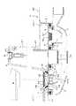
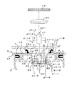
まず、図1及び図2に示す第2の実施の形態について説明すると、この実施の形態は、洗い場側の排水口に対応してトラップを配設し、該トラップに浴槽排水口直下に取付たトラップ接続管を接続した床パン載置型浴槽の排水栓構造を示している。
図1において、符号Aは浴槽載置型床パン、Bは浴槽、1はトラップ、2はトラップ接続管である。
浴槽載置型床パンAは、従来から周知なように一半部の浴槽載置部a1と他半部の洗い場部a2とを土手部a3を介して連設してなり、その浴槽載置部a1にパン排水口3が、洗い場部a2に洗い場排水口4が各々開口されている。
First, the second embodiment shown in FIG. 1 and FIG. 2 will be described. In this embodiment, a trap is disposed corresponding to the drain on the washing place side, and the trap is attached immediately below the bathtub drain. The drain plug structure of the floor pan mounting type bathtub which connected the trap connection pipe is shown.
In FIG. 1, symbol A is a bathtub-mounted floor pan, B is a bathtub, 1 is a trap, and 2 is a trap connecting pipe.
As is well known in the art, the bathtub mounting type floor pan A is formed by connecting one half of the bathtub mounting part a1 and the other half of the washing place a2 via the bank part a3, and the bathtub mounting part a1. In addition, a
洗い場排水口4は、洗い場部a2から一段低く凹設された凹段部a2−1の底に開口されている。
トラップ1は、環状のトラップ締付部材5をその洗い場排水口4を挿通して上端のトラップ開放部に螺嵌することによって洗い場部a2に吊持状に取付けられており、そのトラップ締付部材5にヘアーキャッチャー16を有する蓋6が一体的もしくは係脱可能に係合されており、前記トラップ締付部材5と前記蓋6とでトラップ1のカバーC1を構成している。
The washing ground drainage port 4 is opened at the bottom of the recessed step portion a2-1 that is recessed one step lower than the washing place portion a2.
The
前記トラップ1には、前記トラップ締付部材5下端に形成されている掛止鍔15に封水筒11が引掛けられている。
In the
一方、パン排水口3は、浴槽載置部a1から一段低く凹設した凹窪部a1−1の底に開口されている。
前記トラップ接続管2は、環状の締付部材7を、パン排水口3を挿通して上端の開放部に螺嵌することによって浴槽載置部a1に吊持状に取付られており、その締付部材7に排水目皿18を有する蓋8を一体的もしくは係脱可能に係合して、前記締付部材7と前記蓋8とでトラップ接続管2のカバーC2を構成している。
On the other hand, the
The
前記トラップ接続管2のカバーC2には、遠隔操作式排水栓Dの開閉栓支持部d1を有する排水案内部9が設けられている。この実施の形態では排水案内部9が前記蓋8の周囲の部分に排水目皿18を残すように中央部に設けられている。
そして、前記トラップ接続管2は、接続ホース10を介して前記トラップ1に接続される。
The cover C2 of the
The
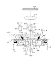
前記排水案内部9は、この実施の形態では図2に示すように浴槽排水口bの下端を内嵌するために前記カバーC2表面高さレベルから立ち上げられた係合部19下端から開閉栓d2の着座面29を求心方向に下向き傾斜状に連設し、その着座面29から排水筒39を垂設し、その排水筒39から求心方向に向かう複数本のリブ49を設けてそのリブ49間を排水空間59とすると共にそのリブ49複数本の先端間で挿脱空間69を確保し、該挿脱空間69に、遠隔操作式排水栓Dの開閉栓支持部d1を抜差し可能に係合し、その開閉栓支持部d1で開閉栓d2を支持する構成になっている。
そして、前記開閉栓支持部d1は、その下端側に前記リブ49の下端に設けた係止凸部49aに係脱する係合凹部d1−1を設け、故意に引抜けば、外れるようになっている。
In this embodiment, as shown in FIG. 2, the drainage guide portion 9 is opened and closed from the lower end of the
The opening / closing stopper support portion d1 is provided with an engaging recess d1-1 that engages with and disengages from a locking protrusion 49a provided at the lower end of the
前記開閉栓支持部d1は、内部中空な支持部本体d1−2内に遠隔操作用の伝達手段であるレリースd3の進動側でロックと、ロック解除とを交互に繰り返す従来から周知のスラストロック機構(図示せず)またはレリースd3の一端側と開閉栓d2の支持軸d2−1とを連絡する連絡部を内蔵してなり、レリースd3の伝達力を受けて支持軸d2−1を介して開閉栓d2が交互に上昇、下降するようになっている。
尚、前記開閉栓支持部d1に前記のように連絡部を内蔵している場合には、操作部側にロックとロック解除を交互に行うスラストロック機構を設けること云うまでもなく、操作部の押し引きで排水栓が上昇、下降する遠隔操作式排水栓の場合には、スラストロック機構は必要ではないものである。
尚、前記係合部19は、前記蓋8に凹設された凹部で構成し、その凹部に前記浴槽排水口bの下端がシール材を介して水密状に嵌合するようにしても良いものである。
The open / close stopper support portion d1 is a well-known thrust lock that alternately repeats locking and unlocking on the moving side of a release d3 that is a transmission means for remote operation in a hollow support portion body d1-2. A mechanism (not shown) or a connecting portion for connecting one end side of the release d3 and the support shaft d2-1 of the opening / closing stopper d2 is built in, and receives the transmission force of the release d3 via the support shaft d2-1. The open / close stopper d2 is alternately raised and lowered.
In the case where the connecting part is incorporated in the opening / closing stopper support part d1, as described above, it is needless to say that a thrust lock mechanism for alternately locking and unlocking is provided on the operation part side. The thrust lock mechanism is not necessary in the case of a remote-operated drain plug in which the drain plug is raised and lowered by pushing and pulling.
The engaging
また、排水案内部9は、図5に示すように前記排水筒39下端に間隔をおいて被載承部79を内側に向けて突設すると共に、その被載承部79間の排水筒39下端に係合溝89を刻設する形成する一方、開閉栓支持部d1を、支持部本体d1−2と、その支持部本体d1−2から放射状に一体に延設したリブd1−3と、そのリブd1−3先端を連結してリブd1−3間に排水空間59を確保する外輪板d1−4と、その外輪板d1−4の下端から縦スリットd1−6を介して下方に垂設された支持脚d1−5とを備え、該支持脚d1−5の下端に弾性係合爪d1−7を設けて、該弾性係合爪d1−7が前記係合溝89に弾性的に係合すると同時にその支持脚d1−5間の外輪板d1−4下端部分が前記被載承部79に載承されるようにして、上方から外輪板d1−4下端が被載承部79に載承されるようにして弾性係合爪d1−7を係合溝89に係合することによって支持部本体d1−2で支持される開閉栓d2を浴槽排水口b内に配置し、弾性係合爪d1−7に対する係合溝89の係合力に抗して上方に引き抜くことによって開閉栓支持部d1が抜取れるようにしても良いものである(特開平11−99077号公報等参照)。
Further, as shown in FIG. 5, the drain guide 9 protrudes from the lower end of the
前記開閉栓支持部d1の下端に一端側が接続される前記レリースd3は、トラップ接続管2の任意箇所に貫通されたゴムブッシュ100に水密状に挿通して配線され、浴槽Bの上縁面や浴槽エプロンb1等所望箇所に設置した操作部d4にその他端側が接続されて、伝達力が付与されるようになっている。
The release d3 whose one end is connected to the lower end of the opening / closing stopper support portion d1 is wired in a watertight manner through a
前記係合部19には立上げ面(内面)19’には緩衝機能を有するシール材19aが貼着されており、そのシール材19aを圧接するように浴槽排水口bの下端を水密状に係合(嵌合)するようになっている。
A sealing
前記開閉栓d2は、前記のように浴槽載置型床パンAに取り付けられるトラップ接続管2のカバーC2に設けた排水案内部9の開閉栓支持部d1に支持されている。
そのため、排水口部材に支持した場合に比べて、その開閉栓支持部d1が低い位置なる。
それ故、開閉栓d2は、着座面29に着座する閉栓状態から開栓状態に移行した時に、浴槽排水口bから槽内に突出しないようになり、その開閉栓d2の上方を、浴槽排水口bを抜差し可能に被蓋する多孔蓋b2で開閉可能にしている。
前記多孔蓋b2は、排水目皿であり、毛髪、水垢等を除去する程度の目の粗さになっている。
The opening / closing stopper d2 is supported by the opening / closing stopper support part d1 of the drainage guide part 9 provided on the cover C2 of the
Therefore, the opening / closing stopper support part d1 is at a lower position as compared with the case where it is supported by the drain port member.
Therefore, the open / close plug d2 does not protrude from the bathtub drainage port b into the tank when the plugged state seated on the
The perforated lid b2 is a drained eye dish, and has an eye roughness enough to remove hair, scales and the like.
以上のように構成されている浴槽の排水栓構造では、浴槽載置型床パンAにトラップ接続管2をカバーC2で吊持状に取付ることによって、自ずと排水空間59を有する排水案内部9と共に遠隔操作式排水栓Dのその開閉栓支持部d1が所定位置に設置される。
そして、上方から浴槽排水口b下端が係合部19に水密状に係合するように設置することによって、開閉栓d2は浴槽排水口b内に収容されて浴槽Bがセットされる。
レリースd3は、予めトラップ接続管2から外部に引き出しておき、浴槽Bのセット後に操作部d4にその他端側が接続される。
そして、開閉栓d2は、浴槽排水口bを被蓋する多孔蓋b2に干渉することなく浴槽排水口b内で上昇、下降を交互に繰り返して開栓、閉栓し、多孔蓋b2で付着除去される毛髪、ゴミ類は、上方から剥がしたり、多孔蓋b2を抜取って取除く。
また、開閉栓d2、開閉栓支持部d1のメンテナンスや交換等は、多孔蓋b2を抜取った後、上方に開閉栓支持部d1を引き抜いて行なえば良いものである。
In the drain plug structure of the bathtub configured as described above, the
And the opening-and-closing stopper d2 is accommodated in the bathtub drainage port b, and the bathtub B is set by installing so that the lower end of the bathtub drainage port b may engage with the engaging
The release d3 is previously pulled out from the
The open / close stopper d2 is alternately opened and closed in the bathtub drainage port b without being interfered with the porous lid b2 covering the bathtub drainage port b, and is attached and removed by the porous lid b2. Remove the hair and trash from above or remove the porous lid b2.
Further, maintenance and replacement of the opening / closing stopper d2 and the opening / closing stopper support part d1 may be performed by pulling out the opening / closing stopper support part d1 upward after removing the porous lid b2.
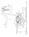
次に図3に示す第2の実施の形態を説明すると、この実施の形態は、前記トラップ接続管2がトラップ1になっている場合の実施の形態であり、封水筒11が締付部材7下端の掛止鍔17に引っ掛けられていることを除けば前記する実施の形態と同様であるため、同一符号を付して具体的説明は省略する。
Next, a second embodiment shown in FIG. 3 will be described. This embodiment is an embodiment in which the
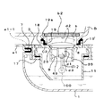
次に図4に示す第3の実施の形態を説明すると、この実施の形態は、床スラブ設置型の浴槽Bの場合を示している。
この実施の形態の浴槽排水口b直下には、トラップ接続管2が床スラブE上方に支持されている。
そのトラップ接続管2は、洗い場排水口に取り付けられたトラップに接続することによって間接的に床スラブE上方位置に支持されており、そのトラップ接続管2の開放部を内周下端に引っ掛け部12aを有する環状部材12と、その環状部材12に係脱可能に係合される蓋22とからなるカバーC2で閉塞し、そのカバーC2に前記第1の実施の形態と同様に開閉栓支持部d1を支持する排水案内部9を一体的に設けている。符号Fは浴槽の支持脚である。
他の構成は前記する第1の実施の形態と同様であるため、同一符号を付して具体的説明は省略する。
尚、この実施の形態の前記トラップ接続管2がトラップの場合も本発明は包含するものである。
Next, a third embodiment shown in FIG. 4 will be described. This embodiment shows a case of a floor slab installation type bathtub B.
The
The
Since other configurations are the same as those of the first embodiment described above, the same reference numerals are given and detailed descriptions thereof are omitted.
In addition, this invention includes the case where the said
A:浴槽載置型床パン 2:トラップ接続管
1:トラップ C1、C2:カバー
D:遠隔操作式排水栓 d2:開閉栓
d1:開閉栓支持部 9:排水案内部
b:浴槽排水口 19:係合部
b2:多孔蓋 19’:立上げ面
19a:シール材 59:排水空間
d3:レリース(伝達手段)
A: Bath-mounted floor pan 2: Trap connection pipe 1: Trap C1, C2: Cover D: Remote-controlled drain plug d2: Open / close stopper d1: Open / close stopper support section 9: Drain guide section b: Bath drain outlet 19: Person Joint part b2: Porous lid 19 ':
Claims (6)
Priority Applications (1)
| Application Number | Priority Date | Filing Date | Title |
|---|---|---|---|
| JP2004104754A JP2005290738A (en) | 2004-03-31 | 2004-03-31 | Bathtub drain plug structure |
Applications Claiming Priority (1)
| Application Number | Priority Date | Filing Date | Title |
|---|---|---|---|
| JP2004104754A JP2005290738A (en) | 2004-03-31 | 2004-03-31 | Bathtub drain plug structure |
Publications (1)
| Publication Number | Publication Date |
|---|---|
| JP2005290738A true JP2005290738A (en) | 2005-10-20 |
Family
ID=35323987
Family Applications (1)
| Application Number | Title | Priority Date | Filing Date |
|---|---|---|---|
| JP2004104754A Pending JP2005290738A (en) | 2004-03-31 | 2004-03-31 | Bathtub drain plug structure |
Country Status (1)
| Country | Link |
|---|---|
| JP (1) | JP2005290738A (en) |
Citations (5)
| Publication number | Priority date | Publication date | Assignee | Title |
|---|---|---|---|---|
| JPS503395Y1 (en) * | 1970-06-15 | 1975-01-29 | ||
| JPH02107884U (en) * | 1989-02-15 | 1990-08-28 | ||
| JPH0489166U (en) * | 1990-12-05 | 1992-08-04 | ||
| JPH09195348A (en) * | 1996-01-18 | 1997-07-29 | Toto Ltd | Drain construction of bathroom |
| JPH10237915A (en) * | 1997-02-21 | 1998-09-08 | Toto Ltd | Drainage construction of bathtub |
-
2004
- 2004-03-31 JP JP2004104754A patent/JP2005290738A/en active Pending
Patent Citations (5)
| Publication number | Priority date | Publication date | Assignee | Title |
|---|---|---|---|---|
| JPS503395Y1 (en) * | 1970-06-15 | 1975-01-29 | ||
| JPH02107884U (en) * | 1989-02-15 | 1990-08-28 | ||
| JPH0489166U (en) * | 1990-12-05 | 1992-08-04 | ||
| JPH09195348A (en) * | 1996-01-18 | 1997-07-29 | Toto Ltd | Drain construction of bathroom |
| JPH10237915A (en) * | 1997-02-21 | 1998-09-08 | Toto Ltd | Drainage construction of bathtub |
Similar Documents
| Publication | Publication Date | Title |
|---|---|---|
| KR20090127911A (en) | Floor drain | |
| JP2007285097A (en) | Drainage apparatus | |
| JP2012036708A (en) | Operation side structure of remote control type drain valve device | |
| KR100614939B1 (en) | Flow backward prevention establishment structure of manhole for road | |
| JP2010053508A (en) | Drain valve device for remote control type | |
| JP2005290738A (en) | Bathtub drain plug structure | |
| JP2021017725A (en) | Drainage structure | |
| JP5706659B2 (en) | Cleaning port lid in drainage pipeline | |
| EP3652387B1 (en) | Water drain kit and a method of installing a water drain | |
| JP4301847B2 (en) | Bath drain connection structure | |
| JP2000220187A (en) | Coupling method between remote operated drain cock and direct drain structure | |
| JPH09125507A (en) | Remodeling method of stool bottom cover and stool for dew proofing and installation working method of stool | |
| JP4322078B2 (en) | Inflow shut-off device for drain cap | |
| JP2002322703A (en) | Drain plug device of bathtub | |
| JP4214189B2 (en) | Remote-controlled drain plug device | |
| JPH03260230A (en) | Drainer for unit bath | |
| JP2006063764A (en) | Perforated plate member used in piping structure for bath tub | |
| EP0202308B1 (en) | Sanitary appliances with an indirect outlet and hidden drainage mechanism | |
| JP2006138065A (en) | Drainage equipment | |
| JP3321639B2 (en) | Drainage equipment | |
| JP2003082736A (en) | Drainage equipment | |
| JP2001098603A (en) | Drain trap | |
| JP2010156180A (en) | Mounting structure of remote drain plug device | |
| JP2004150065A (en) | Operating part of remote operated drain valve device | |
| JP4517054B2 (en) | Drain trap |
Legal Events
| Date | Code | Title | Description |
|---|---|---|---|
| A621 | Written request for application examination |
Free format text: JAPANESE INTERMEDIATE CODE: A621 Effective date: 20060719 |
|
| RD02 | Notification of acceptance of power of attorney |
Free format text: JAPANESE INTERMEDIATE CODE: A7422 Effective date: 20080325 |
|
| A977 | Report on retrieval |
Free format text: JAPANESE INTERMEDIATE CODE: A971007 Effective date: 20080704 |
|
| A131 | Notification of reasons for refusal |
Free format text: JAPANESE INTERMEDIATE CODE: A131 Effective date: 20090811 |
|
| A521 | Written amendment |
Free format text: JAPANESE INTERMEDIATE CODE: A523 Effective date: 20091013 |
|
| A131 | Notification of reasons for refusal |
Free format text: JAPANESE INTERMEDIATE CODE: A131 Effective date: 20091222 |
|
| A02 | Decision of refusal |
Free format text: JAPANESE INTERMEDIATE CODE: A02 Effective date: 20100420 |