JP2005290722A - Soundproofing device - Google Patents
Soundproofing device Download PDFInfo
- Publication number
- JP2005290722A JP2005290722A JP2004104371A JP2004104371A JP2005290722A JP 2005290722 A JP2005290722 A JP 2005290722A JP 2004104371 A JP2004104371 A JP 2004104371A JP 2004104371 A JP2004104371 A JP 2004104371A JP 2005290722 A JP2005290722 A JP 2005290722A
- Authority
- JP
- Japan
- Prior art keywords
- frequency
- soundproofing
- low
- resonance
- ceiling
- Prior art date
- Legal status (The legal status is an assumption and is not a legal conclusion. Google has not performed a legal analysis and makes no representation as to the accuracy of the status listed.)
- Pending
Links
- 238000005192 partition Methods 0.000 claims abstract description 11
- 239000011358 absorbing material Substances 0.000 claims description 12
- 230000000694 effects Effects 0.000 abstract description 12
- 238000009413 insulation Methods 0.000 abstract description 4
- 239000010408 film Substances 0.000 description 10
- 230000004888 barrier function Effects 0.000 description 4
- 230000007423 decrease Effects 0.000 description 4
- 239000000463 material Substances 0.000 description 3
- 239000010409 thin film Substances 0.000 description 2
- 239000011248 coating agent Substances 0.000 description 1
- 238000000576 coating method Methods 0.000 description 1
- 238000010276 construction Methods 0.000 description 1
- 239000000428 dust Substances 0.000 description 1
- 239000011491 glass wool Substances 0.000 description 1
- 239000002184 metal Substances 0.000 description 1
- 230000008833 sun damage Effects 0.000 description 1
- 229920003002 synthetic resin Polymers 0.000 description 1
- 239000000057 synthetic resin Substances 0.000 description 1
- 238000003466 welding Methods 0.000 description 1
Images
Landscapes
- Devices Affording Protection Of Roads Or Walls For Sound Insulation (AREA)
- Building Environments (AREA)
- Soundproofing, Sound Blocking, And Sound Damping (AREA)
Abstract
【課題】 小型で低周波から高周波まで広い周波数範囲にわたる騒音に対して充分な防音効果を有する防音装置を提供する。
【解決手段】 防音壁(2)の上縁に設けられる防音装置(10)において、水平な底部(14)と、水平な天井(12)と、底部と天井間を連結する縦壁(20)及び仕切壁によって区画された複数の低周波共鳴室(22L)と、天井に設けられ低周波共鳴室と外部とを連通する開口とからなる低周波防音部(10L)と、少なくとも一部が傾斜した底部(16)と、傾斜した底部に立設された縦壁及び仕切壁によって区画され天井を有しない複数の高周波共鳴室(22H)とからなる高周波防音部(10H)とを備える。
【選択図】 図1PROBLEM TO BE SOLVED: To provide a soundproof device that is small and has a sufficient soundproofing effect against noise over a wide frequency range from low frequency to high frequency.
SOLUTION: In a soundproofing device (10) provided at an upper edge of a soundproofing wall (2), a horizontal bottom (14), a horizontal ceiling (12), and a vertical wall (20) connecting the bottom and the ceiling. And a plurality of low-frequency resonance chambers (22L) partitioned by a partition wall, and a low-frequency sound insulation portion (10L) comprising an opening that is provided on the ceiling and communicates with the low-frequency resonance chambers and the outside, and at least partly inclined And a high-frequency soundproofing section (10H) comprising a plurality of high-frequency resonance chambers (22H) partitioned by vertical walls and partition walls standing on the inclined bottom section and having no ceiling.
[Selection] Figure 1
Description
本発明は、道路、鉄道、工場等からの騒音を遮断する防音壁の上縁に取り付けられる防音装置に関するものである。 The present invention relates to a soundproofing device that is attached to the upper edge of a soundproofing wall that blocks noise from roads, railways, factories, and the like.
従来の防音壁は、高くすることにより、騒音を遮断しようとしていた。しかしながら、防音壁の高さを高くすると、強い風圧を受けたり、工費が高くなったり、日照被害を大きくしたり、見晴らしが悪くなったりと、不都合なことが多くなり、防音壁の高さには限界があった。また、単に防音壁を高くしただけでは、低周波の騒音は、防音壁の上縁で回折して受音者側に到達するため、充分に騒音を遮断することができなかった。 Conventional noise barriers tried to block noise by increasing the height. However, increasing the height of the sound barrier increases inconveniences, such as receiving strong wind pressure, increasing construction costs, increasing sun damage, and worsening the view. There was a limit. Further, simply raising the noise barrier, the low frequency noise is diffracted at the upper edge of the noise barrier and reaches the sound receiver side, so that the noise cannot be sufficiently blocked.
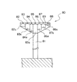
このため、下記特許文献1では、図6に示したような防音装置80を提案している。この防音装置80は、防音壁81の上縁に設けるもので、水平な閉塞部材89の下面に空洞部82a−88aが取り付けられ、各空洞部82a−88aが閉塞部材89に設けられた開口82−88によって外部と連通するものである。各空洞部82a−88aは、ヘルムホルツ共鳴器と呼ばれ、音速c、開口82−88の開口面積s、開口82−88の首下長さd、空洞部82a−88aの容積Vによって定まる共振周波数foを有している。空洞部82a−88aの共振周波数foは、次の(1)式で決まる。
For this reason, the following Patent Document 1 proposes a
fo={c/(2π)}√{s/(d・V)} (1)
たとえば、c=340m/s、V=0.02m3、s=10cm2、d=1cmとすると、fo=121Hzとなる。ここで、各空洞部82a−88aは、互いの容積Vを変えて、各空洞部82a−88aの共振周波数foを互いに少しづつ変えてある。
fo = {c / (2π)} √ {s / (d · V)} (1)
For example, when c = 340 m / s, V = 0.02 m 3 , s = 10 cm 2 , and d = 1 cm, fo = 121 Hz. Here, each
共振周波数fo以上の騒音が防音装置80の上側に来ると、空洞部82a−88a内の空気は騒音と逆位相で振動し、騒音の音圧を下げることになる。特に、共振周波数付近の騒音に対しては、空洞部82a−88a内の空気が共振するので、効果的に騒音を低減できる。こうして、騒音の音圧が下がると、防音装置80上を回折する騒音も減少する。また、前記(1)式で定まる共振周波数foは空洞部82a−88aが小さくても充分低くくなるとともに、各空洞部82a−88aの共振周波数foを互いに少しづつ変えているので、この防音装置80は低周波領域の広い範囲にわたって騒音を効果的に減少させることができる。しかも、各空洞部82a−88aで発生する共鳴音は、開口82−88が上方を向いているため上方にのみ放射され、受音者の方へは放射されないので、共鳴音が騒音となることもない。
しかしながら、前記特許文献1に記載された防音装置80は、小型ながら、各空洞部82a−88aの共振周波数foが低いため、低周波の騒音に大きな防音効果があるものの、逆に高周波の騒音については防音効果が不十分であるという問題があった。
However, although the
本発明は、前記問題に鑑みてなされたものであり、小型で低周波から高周波まで広い周波数範囲にわたる騒音に対して充分な防音効果を有する防音装置を提供することを課題とする。 This invention is made | formed in view of the said problem, and makes it a subject to provide the soundproofing apparatus which has sufficient soundproofing effect with respect to the noise over a wide frequency range from a low frequency to a high frequency.
前記課題を解決するために、請求項1に係る発明は、防音壁の上縁に設けられる防音装置において、底部と、水平な天井と、前記底部と前記天井の間を連結する縦壁及び仕切壁によって区画された低周波共鳴室と、前記天井に設けられ前記低周波共鳴室と外部とを連通する開口とからなる低周波防音部と、底部と、底部に立設された縦壁及び仕切壁によって区画され天井を有しない高周波共鳴室とからなる高周波防音部とを備えたことを特徴とする。 In order to solve the above-mentioned problem, the invention according to claim 1 is the soundproofing device provided at the upper edge of the soundproofing wall, and includes a bottom part, a horizontal ceiling, and a vertical wall and a partition connecting the bottom part and the ceiling. A low-frequency sound insulation section comprising a low-frequency resonance chamber partitioned by a wall, an opening provided in the ceiling for communicating the low-frequency resonance chamber and the outside; a bottom; a vertical wall and a partition standing on the bottom; A high-frequency soundproofing unit including a high-frequency resonance chamber partitioned by walls and having no ceiling is provided.
請求項2に係る発明は、請求項1に係る発明において、前記低周波共鳴室は複数設けられ、各低周波共鳴室の共振周波数は互いに異ならせてあり、前記高周波共鳴室も複数設けられ、各高周波共鳴室の共振周波数は、各高周波共鳴室の深さを変えることにより、互いに異ならせてあることを特徴とする。
The invention according to
請求項3に係る発明は、請求項1または2に係る発明において、前記低周波防音部及び高周波防音部の上面にはフィルムを張り付けたことを特徴とする。
The invention according to claim 3 is characterized in that, in the invention according to
請求項4に係る発明は、請求項1、2又は2に係る発明において、受音者側端及び音源側端の少なくとも一方には吸音材が取り付けられたことを特徴とする。
The invention according to claim 4 is the invention according to
請求項1に係る発明によれば、この防音装置は、底部と、水平な天井と、前記底部と前記天井間を連結する縦壁及び仕切壁によって区画された低周波共鳴室と、天井に設けられ低周波共鳴室と外部とを連通する開口とからなる低周波防音部と、底部と、該底部に立設された縦壁及び仕切壁によって区画され天井を有しない高周波共鳴室とからなる高周波防音部とを備えたから、小型の防音装置でありながら、低周波から高周波までの広い周波数領域の騒音に対して充分な防音効果を有する。 According to the first aspect of the present invention, the soundproofing device is provided on the ceiling, a horizontal ceiling, a low frequency resonance chamber defined by a vertical wall and a partition wall connecting the bottom and the ceiling, and the ceiling. A high-frequency resonance chamber composed of a low-frequency sound insulation portion comprising an opening that communicates the low-frequency resonance chamber with the outside, a bottom portion, and a high-frequency resonance chamber that is partitioned by a vertical wall and a partition wall standing on the bottom portion and has no ceiling Since the soundproof unit is provided, the soundproofing device has a sufficient soundproofing effect against noise in a wide frequency range from a low frequency to a high frequency while being a small soundproof device.
請求項2に係る発明によれば、さらに、低周波共鳴室及び高周波共鳴室は、それぞれ複数設けられ、それらの共振周波数は互いに異ならせてあるので、低周波から高周波までの広い周波数領域の騒音に対して、いっそう充分な防音効果を有する。 According to the second aspect of the present invention, a plurality of low frequency resonance chambers and high frequency resonance chambers are provided, and the resonance frequencies thereof are different from each other. In contrast, it has a more sufficient soundproofing effect.
請求項3に係る発明によれば、さらに、前記低周波防音部及び高周波防音部の上面にはフィルムを張り付けたから、各共鳴室の共振周波数から離れた周波数の騒音に対しても、防音効果が大きくなる。 According to the third aspect of the present invention, since the films are attached to the upper surfaces of the low-frequency soundproofing portion and the high-frequency soundproofing portion, the soundproofing effect is also provided for noise having a frequency away from the resonance frequency of each resonance chamber. growing.
請求項4に係る発明によれば、さらに、防音装置の受音者側端及び音源側端の少なくとも一方には吸音材が取り付けられたから、高周波の騒音が吸音され、いっそう防音効果が大きくなる。 According to the fourth aspect of the present invention, since the sound absorbing material is attached to at least one of the sound receiver side end and the sound source side end of the soundproofing device, high frequency noise is absorbed, and the soundproofing effect is further increased.
以下、本発明の好ましい実施の形態を添付図面に基づいて詳細に説明する。 Preferred embodiments of the present invention will be described below in detail with reference to the accompanying drawings.
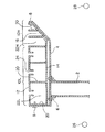
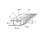
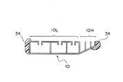
図1は、本発明の第1実施例の防音装置の横断面図である。図2は、前記防音装置の斜視図である。本実施例の防音装置10は、低周波の騒音を減少させる低周波防音部10Lと、高周波の騒音を減少させる高周波防音部10Hと、両防音部10L、10Hの天井面以外を覆うカバー4とからなる。両防音部10L、10Hは、互いに連結され、両端をボルト8によってカバー4に固定され、カバー4はボルト6によって防音壁2の上端に固定される。
FIG. 1 is a cross-sectional view of a soundproofing device according to a first embodiment of the present invention. FIG. 2 is a perspective view of the soundproofing device. The
低周波防音部10Lは、水平な天井12と、水平な底部14と、天井12と底部18と連結する縦壁20とを有し、天井12と縦壁20と底部14で区画される空洞すなわち低周波共鳴室22Lからなる。天井12には、各低周波共鳴室22Lと外部とを連通するスリット(開口)24が設けられる。各低周波共鳴室22Lは、長手方向(防音壁2に沿う方向)に沿って適宜間隔で仕切壁30(図2参照)で区切られる。そして、各低周波共鳴室22Lの容積V、スリット24の開口面積s、スリット24の首下長さdを少しづつ変えて、各低周波共鳴室22Lの共振周波数foも互いに少しづつ変わるようにしている。各低周波共鳴室22Lの共振周波数foは、音源26の出す騒音の周波数分布に応じて適切に選定される。低周波防音部10Lは、前記特許文献1に記載された防音装置と同じ原理によって、低周波領域の広い範囲にわたって騒音を減少させる。
The low-frequency soundproofing part 10L has a
低周波防音部10Lの受音者28側端には、高周波防音部10Hが溶接等適宜手段によって結合される。高周波防音部10Hは、少なくとも一部が幅方向に傾斜した底部16と、底部16に立設された縦壁20と、底部16と縦壁20で区画される上方に開放された空洞すなわち高周波共鳴室22Hからなる。各高周波共鳴室22Hも、防音壁2方向に沿って適宜間隔で仕切壁30で区切られている。各高周波共鳴室22Hの深さLは、傾斜した底部16のために少しづつ変わっており、これによって、各高周波共鳴室22Hの共振周波数foも互いに少しづつ変わるようになっている。
The high frequency soundproofing part 10H is coupled to the end of the low frequency soundproofing part 10L on the
各高周波共鳴室22Hは、複数の縦壁20と傾斜した底部16によって形成したから、水平な底を個々に有する共鳴室を形成するよりも、少ない部品数で済むうえ、安価で容易に製造できる。また、防音装置10を長手方向に沿ってわずかに傾斜させておくと、各高周波共鳴室22Hに雨水等が侵入しても、各高周波共鳴室22Hの傾斜した底部16の最も低い部分に沿って雨水等を確実に流して水はけを良くすることができ、防音装置10の耐久性を高めることができる。
Since each high-
高周波防音部10Hの高周波共鳴室22H内の気柱が共鳴するのは、高周波共鳴室22Hの底部16が節で開口部が腹となる定常波が、入射波と反射波の干渉によって発生するときである。したがって、定常波の節と腹の間隔は、入射波の1/4であるから、高周波共鳴室22Hの深さLの4倍の波長を有する音波が入射すると、高周波共鳴室22Hは共鳴し、その共振周波数foは、音速cとすると、次の(2)式のとおりである。
fo=c/(4L) (2)
たとえば、c=340m/s、L=9cmとすると、fo=944Hzとなる。したがって、高周波共鳴室22Hはコンパクトに設計できるので、防音装置10の小型化を維持できる。各高周波共鳴室22Hの共振周波数foも、音源26の出す騒音の周波数分布に応じて適切に選定される。
The air column in the high-
fo = c / (4L) (2)
For example, when c = 340 m / s and L = 9 cm, fo = 944 Hz. Therefore, since the high
この高周波防音部10Hにおいても、共振周波数fo以上の騒音が防音装置10の上側に来ると、各高周波共鳴室22H内の空気は騒音と逆位相で振動し、騒音の音圧を下げることになる。特に、共振周波数fo付近の騒音に対しては、高周波共鳴室22H内の空気が共振するので、効果的に騒音を低減できる。そして、共振周波数foを人が最も敏感に感じる1000−2000Hz付近にすることが容易なので、騒音の低減効果を極めて大きくできる。また、高周波防音部10Hは、各高周波共鳴室22Hの共振周波数foが互いに少しづつ変わるようにしているため、高周波領域の広い範囲にわたって騒音を効果的に減少させることができる。こうして、騒音の音圧が下がると、防音装置10上を回折する騒音も減少する。しかも、各高周波共鳴室22Hで発生する共鳴音は、上方にのみ放射され、受音者28の方へ放射されないので、共鳴音が騒音となることもない。
Also in the high frequency soundproofing unit 10H, when noise having a resonance frequency fo or higher comes to the upper side of the
この防音装置10各部の材料は、所定の対候性と強度を有するものであれば、金属、合成樹脂等、どのようなものでもよい。この防音装置10は、数メートルの長さユニットからなる、これらのユニットを防音壁2上で互いに端部を接続して防音装置10全体を構成する。そして、防音装置10の幅はできる限り大きくすることが望ましい。
The material of each part of the
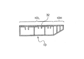
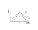
図3に、本発明の第2実施例を示す。本実施例は、前記第1実施例の防音装置10の低周波防音部10L及び高周波防音部10Hの上面に薄い膜状のフィルム32を張り付けたものである。図4に示したように、共鳴室22L、22Hにフィルム32を張り付けたものE2は、フィルム32を張り付けないものE1と共振周波数foは変わらないが、共振周波数foから離れた周波数領域での吸音率が大きく、全体的に防音効果が大きくなる。また、このフィルム32は、塵埃や雨水等から防音装置10内部を保護する働きもある。
FIG. 3 shows a second embodiment of the present invention. In this embodiment, a
図5に、本発明の第3実施例を示す。音波の回折の量は回折部の音圧と比例するため、端部に吸音材を配置することにより、すなわち、本実施例は、前記第1実施例の防音装置10の端部に吸音材34を配置することにより、回折する騒音を減少させるものであり、防音装置10の音源側端と受音者側端の両方に吸音材34を取り付けている。吸音材34には、グラスウール等の多孔質吸音材を耐候性フィルムで被覆したもの等が用いられる。本実施例によれば、吸音材34が800Hz以上の高周波の騒音を良く吸収するので、いっそう防音効果が大きくなる。もちろん、音源側端と受音者側端の一方のみに吸音材34を取り付けるだけでも、充分な防音効果がある。
FIG. 5 shows a third embodiment of the present invention. Since the amount of sound wave diffraction is proportional to the sound pressure of the diffracting portion, the
ところで、本発明は、前記実施例に限るものではなく、例えば、次のように変形してもよい。 By the way, the present invention is not limited to the above embodiment, and may be modified as follows, for example.
前記第1実施例の防音装置10の上面に薄い膜状のフィルム32を張り付けるとともに、音源側端部と受音者端部には吸音材34を取り付けてもよい。また、防音装置10は、低周波防音部10Lの天井12を異なる開口面積sと首下長さdを有するものと交換可能にされ、また、高周波防音部10Hを異なる共振周波数foの高周波共鳴室22Hを有するものと交換可能にしてもよい。こうすることにより、音源26の周波数分布に応じて各共鳴室22L、22Hの共振周波数foを適切に変更することにより、最適の防音装置10を容易に得ることができる。さらに、低周波防音部10Lは、底部14を水平にする必要はなく、水はけを良くするために、防音装置10自体を長手方向にわずかに傾斜させるとともに、その底部14に幅方向にもわずかな傾斜を与えてもよい。
A
10 防音装置
10L 低周波防音部
10H 高周波防音部
12 天井
14 水平な底部
16 傾斜する底部
20 縦壁
22L 低周波共鳴室
22H 高周波共鳴室
24 スリット(開口)
30 仕切壁
32 フィルム
34 吸音材
DESCRIPTION OF
30
Claims (4)
底部と、水平な天井と、前記底部と前記天井の間を連結する縦壁及び仕切壁によって区画された低周波共鳴室と、前記天井に設けられ前記低周波共鳴室と外部とを連通する開口とからなる低周波防音部と、
底部と、底部に立設された縦壁及び仕切壁によって区画され天井を有しない高周波共鳴室とからなる高周波防音部とを備えたことを特徴とする防音装置。 In the soundproofing device provided at the upper edge of the soundproofing wall,
A bottom, a horizontal ceiling, a low-frequency resonance chamber defined by a vertical wall and a partition wall connecting the bottom and the ceiling, and an opening provided in the ceiling for communicating the low-frequency resonance chamber and the outside A low-frequency soundproofing part consisting of
A soundproofing device comprising: a bottom, and a high-frequency soundproofing section including a vertical wall and a partition wall standing on the bottom and a high-frequency resonance chamber having no ceiling.
Priority Applications (1)
| Application Number | Priority Date | Filing Date | Title |
|---|---|---|---|
| JP2004104371A JP2005290722A (en) | 2004-03-31 | 2004-03-31 | Soundproofing device |
Applications Claiming Priority (1)
| Application Number | Priority Date | Filing Date | Title |
|---|---|---|---|
| JP2004104371A JP2005290722A (en) | 2004-03-31 | 2004-03-31 | Soundproofing device |
Publications (1)
| Publication Number | Publication Date |
|---|---|
| JP2005290722A true JP2005290722A (en) | 2005-10-20 |
Family
ID=35323971
Family Applications (1)
| Application Number | Title | Priority Date | Filing Date |
|---|---|---|---|
| JP2004104371A Pending JP2005290722A (en) | 2004-03-31 | 2004-03-31 | Soundproofing device |
Country Status (1)
| Country | Link |
|---|---|
| JP (1) | JP2005290722A (en) |
Cited By (6)
| Publication number | Priority date | Publication date | Assignee | Title |
|---|---|---|---|---|
| KR100834294B1 (en) | 2008-02-21 | 2008-05-30 | 태성이엔씨(주) | Sound-absorbing sound insulation board with multi-diffraction interference slit |
| KR100917033B1 (en) | 2007-09-05 | 2009-09-10 | (주) 케이 이엔씨 | High performance interference device for noise reduction |
| KR20160010045A (en) * | 2014-07-18 | 2016-01-27 | 한국철도기술연구원 | Noise absorption panel on under-body for a high-speed train |
| JP2020144246A (en) * | 2019-03-07 | 2020-09-10 | 株式会社豊田中央研究所 | Slit forming member and shield |
| CN113996430A (en) * | 2021-10-21 | 2022-02-01 | 山东鑫海矿业技术装备股份有限公司 | Assembled sound-proof housing and broken system of vortex that noise reduction effect is good |
| CN116206587A (en) * | 2022-08-02 | 2023-06-02 | 广州大学 | Noise reduction device for jet reinforced grinding processing equipment |
-
2004
- 2004-03-31 JP JP2004104371A patent/JP2005290722A/en active Pending
Cited By (9)
| Publication number | Priority date | Publication date | Assignee | Title |
|---|---|---|---|---|
| KR100917033B1 (en) | 2007-09-05 | 2009-09-10 | (주) 케이 이엔씨 | High performance interference device for noise reduction |
| KR100834294B1 (en) | 2008-02-21 | 2008-05-30 | 태성이엔씨(주) | Sound-absorbing sound insulation board with multi-diffraction interference slit |
| KR20160010045A (en) * | 2014-07-18 | 2016-01-27 | 한국철도기술연구원 | Noise absorption panel on under-body for a high-speed train |
| KR101595798B1 (en) | 2014-07-18 | 2016-02-19 | 한국철도기술연구원 | Noise absorption panel on under-body for a high-speed train |
| JP2020144246A (en) * | 2019-03-07 | 2020-09-10 | 株式会社豊田中央研究所 | Slit forming member and shield |
| JP7213723B2 (en) | 2019-03-07 | 2023-01-27 | 株式会社豊田中央研究所 | Slit forming member and shield |
| CN113996430A (en) * | 2021-10-21 | 2022-02-01 | 山东鑫海矿业技术装备股份有限公司 | Assembled sound-proof housing and broken system of vortex that noise reduction effect is good |
| CN113996430B (en) * | 2021-10-21 | 2023-01-10 | 山东鑫海矿业技术装备股份有限公司 | An assembled sound insulation cover and vortex crushing system for noise reduction |
| CN116206587A (en) * | 2022-08-02 | 2023-06-02 | 广州大学 | Noise reduction device for jet reinforced grinding processing equipment |
Similar Documents
| Publication | Publication Date | Title |
|---|---|---|
| US5681072A (en) | Sound absorber for motor vehicles | |
| JP5326472B2 (en) | Sound absorption structure | |
| US8544601B2 (en) | Sound-absorbing noise barrier | |
| KR101668676B1 (en) | Soundproof panel for decreasing wind load and soundproof wall using the same | |
| KR101260823B1 (en) | Diffraction noise reduction device for noise barrier upper edge using helmholtz resonance absorber | |
| JP2005290722A (en) | Soundproofing device | |
| KR102273933B1 (en) | Resonant module with fin and soundproof wall using the same | |
| JPH09221721A (en) | Soundproofing equipment for roadsides and tunnels | |
| JP3523826B2 (en) | Soundproofing | |
| JP3640648B2 (en) | Soundproof device | |
| JP7542988B2 (en) | Sound absorbers and sound absorbing structures | |
| JP2005146650A (en) | Sound absorbing structure | |
| KR102103576B1 (en) | Air-passing soundproof panel and Air-passing soundproof wall | |
| KR101104997B1 (en) | Prefabricated sound insulation board with center support | |
| KR102107133B1 (en) | Soundproof wall with acoustic block | |
| JP4258288B2 (en) | Sound absorbing structure | |
| JP2000148158A (en) | Slit structure sound absorbing panel | |
| KR20160031220A (en) | Soundproof Panel Unit and Soundproof Wall | |
| JP2015227939A (en) | Resonator type sound absorber | |
| JP2014084578A (en) | Noise reduction structure and construction method for noise reduction structure | |
| JPH08246421A (en) | Resonator type soundproof panel | |
| JP6858394B2 (en) | louver | |
| JP2004232357A (en) | Noise barrier | |
| JP4673504B2 (en) | Sound absorbing and insulating panel and soundproof wall using the same | |
| JP2005017636A (en) | Sound absorbing structure |