JP2005290518A - Method and apparatus for applying powder lubricant - Google Patents
Method and apparatus for applying powder lubricant Download PDFInfo
- Publication number
- JP2005290518A JP2005290518A JP2004110440A JP2004110440A JP2005290518A JP 2005290518 A JP2005290518 A JP 2005290518A JP 2004110440 A JP2004110440 A JP 2004110440A JP 2004110440 A JP2004110440 A JP 2004110440A JP 2005290518 A JP2005290518 A JP 2005290518A
- Authority
- JP
- Japan
- Prior art keywords
- powder lubricant
- powder
- cavity
- lubricant
- charging gun
- Prior art date
- Legal status (The legal status is an assumption and is not a legal conclusion. Google has not performed a legal analysis and makes no representation as to the accuracy of the status listed.)
- Pending
Links
Images


Classifications
-
- B—PERFORMING OPERATIONS; TRANSPORTING
- B30—PRESSES
- B30B—PRESSES IN GENERAL
- B30B15/00—Details of, or accessories for, presses; Auxiliary measures in connection with pressing
- B30B15/0005—Details of, or accessories for, presses; Auxiliary measures in connection with pressing for briquetting presses
- B30B15/0011—Details of, or accessories for, presses; Auxiliary measures in connection with pressing for briquetting presses lubricating means
Landscapes
- Engineering & Computer Science (AREA)
- Mechanical Engineering (AREA)
- Powder Metallurgy (AREA)
Abstract
【課題】 摩擦帯電方式であっても構成が簡単で、効率的に所望の位置に粉末潤滑剤を付着させることができ、しかもコンパクトな帯電ガンにすることができる粉末潤滑剤の塗布方法と装置を提供する。
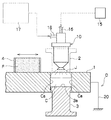
【解決手段】 成形型1に形成されたキャビティC内に充填された成形粉末Fを、上部および下部の加圧体2,3により圧縮成形する前に、予め帯電ガン10により帯電させた粉末潤滑剤Jを前記キャビティCに塗布する塗布する場合、導電体により形成した成形型1を電気的に接地し、キャビティの側面Caが保有する電場強度を下げた後、帯電ガン10により帯電させた粉末潤滑剤Fを塗布することを特徴とする。
【選択図】図1PROBLEM TO BE SOLVED: To provide a powder lubricant application method and apparatus which is simple in configuration even if it is a frictional charging system, can efficiently attach a powder lubricant to a desired position, and can be made into a compact charging gun. I will provide a.
Powder lubrication in which a molding powder F filled in a cavity C formed in a molding die 1 is charged in advance by a charging gun 10 before being compression-molded by upper and lower pressure bodies 2 and 3 is provided. When the agent J is applied to the cavity C, the powder 1 charged by the charging gun 10 after electrically grounding the molding die 1 formed of a conductor and lowering the electric field strength held by the side surface Ca of the cavity. Lubricant F is applied.
[Selection] Figure 1
Description
本発明は、成形粉末を圧縮成形するときに使用される粉末潤滑剤の塗布方法と塗布装置に関する。 The present invention relates to a method and an apparatus for applying a powder lubricant used when compression molding a molded powder.
たとえば、焼結部品の成形は、予め成形型のキャビティ内に充填された成形粉末を上部および下部の加圧体により圧縮成形した後、これを取り出して炉内で焼結するが、この圧縮成形時や取り出し時には、型面と成形粉末との間あるいは成形粉末の粒子相互間に摩擦が生じる。この摩擦は、キャビティ内の成形粉末に作用する成形圧力の伝播を不均一にし、密度差を生じさせ、製品の品質に悪影響を及ぼしたり、成形型の寿命にも影響することになる。 For example, in the molding of sintered parts, the molding powder previously filled in the cavity of the molding die is compression-molded by the upper and lower pressure bodies and then taken out and sintered in a furnace. Friction occurs between the mold surface and the molded powder or between the particles of the molded powder at the time and during removal. This friction makes the propagation of the molding pressure acting on the molding powder in the cavity non-uniform, causes a density difference, adversely affects the quality of the product, and also affects the life of the mold.
このため、従来から成形粉末に潤滑剤を添加し、各部位に生じる摩擦の低減を図っているが、一般に使用される潤滑剤としては、脂肪酸やステアリン酸亜鉛、ステアリン酸リチウムなどの金属ステアレイトであり、添加量は、後の焼結加熱時の気化容易性、炉の損傷防止、成形圧力と圧粉密度の関係などを考慮し、通常、0.5〜1.0重量%程度とされている。 For this reason, a lubricant is conventionally added to the molded powder to reduce the friction generated in each part. However, as a commonly used lubricant, a metal stearate such as fatty acid, zinc stearate or lithium stearate is used. The amount added is usually about 0.5 to 1.0% by weight in consideration of evaporability at the time of subsequent sintering heating, prevention of furnace damage, the relationship between the molding pressure and the green density, and the like. ing.
この潤滑剤は、成形型の型面と成形粉末との間の摩擦を低減し、高圧成形を可能にするため、成形型の型面に塗布することもあるが、潤滑剤を成形型の型面における所定部位に適量塗布することは難しく、従来からこの点に関する種々の提案がなされている。 This lubricant may be applied to the mold surface of the mold in order to reduce friction between the mold surface of the mold and the molding powder and enable high pressure molding. It is difficult to apply an appropriate amount to a predetermined part of the surface, and various proposals regarding this point have been made.
これら提案は、主として、粉末潤滑剤を摩擦により静電気的に帯電させて塗布する方法と、コロナ放電により発生したイオンで帯電させて塗布する方法に大別できるが、いずれも金型に粉末潤滑剤をクーロン力で付着させるもので、それぞれ一長一短があることから、最近では下記特許文献1に示すものが提案されている。
These proposals can be roughly divided into a method in which powder lubricant is electrostatically charged by friction and applied, and a method in which the powder lubricant is charged with ions generated by corona discharge and applied. Are attached by Coulomb force, and each has advantages and disadvantages, and recently, the one shown in
特許文献1の提案は、帯電ガンを用いた摩擦帯電方式の塗布装置であり、ポンプに送るポンプエアー、ポンプから帯電ガンに輸送するパージエアーを圧力制御し、帯電ガンに輸送する粉末潤滑剤の量を規制し、金型内に付着する粉末潤滑剤の量を均一にするものである。
The proposal of
しかし、この塗布装置は、その構成や制御が極めて複雑なばかりでなく、基本的には重力を利用してキャビティ内に粉末潤滑剤を散布するものであることから、金型の所望の位置、特に、重力の影響を受けて付着しにくい金型キャビティの側面には、その形状が複雑なほど十分粉末潤滑剤を付着させることはできないものである。 However, this coating apparatus is not only extremely complicated in its configuration and control, but basically uses a gravity to disperse the powder lubricant in the cavity, so that the desired position of the mold, In particular, the powder lubricant cannot be sufficiently adhered to the side surface of the mold cavity, which is difficult to adhere due to the influence of gravity, as the shape thereof is complicated.
また、従来から使用されている帯電ガン自体も問題を有している。帯電ガンは、外筒内に摩擦体が設けられたものあるいは摩擦体がなく外筒のみから構成されたものがあるが、前者は外筒の内壁と摩擦体との隙間に沿って粉末潤滑剤を圧縮エアーにより輸送し、この輸送途中に粉末潤滑剤が外筒の内壁や摩擦体の外表面と接し、擦られ、静電気的に帯電された後、噴射される。後者のものも基本的には同様で、粉末潤滑剤が外筒の内壁と接し、擦られ、静電気的に帯電された後、噴射される。 The charging gun itself that has been used conventionally also has a problem. Some charging guns are provided with a friction body in the outer cylinder or are constituted only by the outer cylinder without a friction body, but the former is a powder lubricant along the gap between the inner wall of the outer cylinder and the friction body. The powder lubricant is in contact with the inner wall of the outer cylinder and the outer surface of the friction body, and is rubbed, electrostatically charged and then sprayed. The latter is basically the same, and the powder lubricant is in contact with the inner wall of the outer cylinder, rubbed, electrostatically charged and then injected.
しかし、いずれのものも、粉末潤滑剤が十分帯電した状態とするには、接触摩擦により帯電させる帯電部の長さがある程度必要であることから、帯電ガンの全体形状が大型化するという不具合がある。
本発明は、上記従来技術に伴う課題を解決し、摩擦帯電方式であっても構成が簡単で、効率的に所望の位置に粉末潤滑剤を付着させることができ、しかもコンパクトな帯電ガンにすることができる粉末潤滑剤の塗布方法と装置を提供することを目的とする。 The present invention solves the problems associated with the above-described prior art, has a simple structure even with the triboelectric charging method, and can efficiently attach a powder lubricant to a desired position, and a compact charging gun. An object of the present invention is to provide a powder lubricant application method and apparatus that can be applied.
かかる目的を達成する本発明に係る粉末潤滑剤の塗布方法は、成形型に形成されたキャビティ内に充填された成形粉末を、上部および下部の加圧体により圧縮成形する前に、予め帯電ガンにより帯電させた粉末潤滑剤を前記キャビティ内に塗布する粉末潤滑剤の塗布方法であって、導電体により形成した前記成形型を電気的に接地し、キャビティの側面が保有する電場強度を下げた後、前記帯電ガンにより帯電させた前記粉末潤滑剤を塗布することを特徴とする。 The powder lubricant application method according to the present invention that achieves such an object includes a method in which a charging gun is previously charged before compression molding of a molding powder filled in a cavity formed in a molding die with upper and lower pressure bodies. A method for applying a powder lubricant charged in the cavity into the cavity, wherein the mold formed by a conductor is electrically grounded, and the electric field strength possessed by the side surface of the cavity is lowered. Then, the powder lubricant charged by the charging gun is applied.
また、上記目的を達成する本発明に係る粉末潤滑剤の塗布装置は、成形型に形成されたキャビティ内に充填された成形粉末を、上部および下部の加圧体により圧縮成形する前に、予め帯電ガンにより帯電させた粉末潤滑剤を前記キャビティに塗布する粉末潤滑剤の塗布装置であって、導電体により形成した前記成形型を電気的に接地し、キャビティの側面が保有する電場強度を下げる電場降下手段を有することを特徴とする。 In addition, the powder lubricant application device according to the present invention that achieves the above object is provided in advance before the molding powder filled in the cavity formed in the molding die is compression molded by the upper and lower pressure bodies. A powder lubricant application device for applying powder lubricant charged by a charging gun to the cavity, and electrically grounding the molding die formed of a conductor to lower the electric field strength possessed by the side surface of the cavity. It has an electric field dropping means.
前記帯電ガンは、外筒内に前記粉末潤滑剤が輸送されかつ内周面との接触摩擦により粉末潤滑剤を帯電させる摩擦体を有し、該摩擦体の軸方向長さが可及的に長くなるように当該摩擦体を前記外筒内に螺旋状に設けたことを特徴とする。 The charging gun has a friction body in which the powder lubricant is transported into an outer cylinder and charges the powder lubricant by contact friction with an inner peripheral surface, and the axial length of the friction body is as much as possible. The friction body is provided in a spiral shape in the outer cylinder so as to be long.
上記のように構成した本発明は、成形型を電気的に接地し、キャビティの側面が保有する電場強度を下げると、帯電した粉末潤滑剤とキャビティの側面との間に働く電場の強度を高めることができ、重力の影響を受けても帯電した粉末潤滑剤をキャビティの側面に強力に付着させることができる。したがって、粉末潤滑剤の付着が好ましい部位に対し選択的効率的に粉末潤滑剤を付着させ、圧縮成形時や型内から成形体を取り出すときの型面と成形粉末との間に生じる摩擦を確実に低減し、製品品質の向上、成形型の長寿命化を図ることができる。 In the present invention configured as described above, when the mold is electrically grounded and the electric field strength held by the side surface of the cavity is lowered, the strength of the electric field acting between the charged powder lubricant and the side surface of the cavity is increased. The charged powder lubricant can be strongly attached to the side surface of the cavity even under the influence of gravity. Therefore, the powder lubricant is selectively and efficiently attached to the part where the powder lubricant is preferably attached, and the friction generated between the mold surface and the molding powder during compression molding or taking out the molded body from the mold is ensured. To improve product quality and extend the life of the mold.
また、接触摩擦により粉末潤滑剤を帯電させる摩擦体の軸方向長さが長くなるように螺旋状にすると、外筒の長さが短くても、粉末潤滑剤を帯電させる経路の長さは実質的に長くなり、粉末潤滑剤の帯電性が向上するのみでなく、帯電ガンの全体形状もコンパクト化し、スペース面でも作業性の面でも有利となる。 In addition, if the friction body for charging the powder lubricant by contact friction is spiraled so that the axial length is long, the length of the path for charging the powder lubricant is substantially reduced even if the length of the outer cylinder is short. Therefore, not only the charging property of the powder lubricant is improved, but also the overall shape of the charging gun is reduced, which is advantageous in terms of space and workability.
以下、本発明の実施の形態を、図面を参照しつつ説明するが、まず、粉末潤滑剤の塗布装置について述べ、この装置を用いて行なう粉末潤滑剤の塗布方法に及ぶこととする。 Hereinafter, embodiments of the present invention will be described with reference to the drawings. First, a powder lubricant application apparatus will be described, and the powder lubricant application method performed using this apparatus will be described.
図1は本実施形態に係る粉末潤滑剤の塗布装置を示す概略断面図、図2は帯電ガンの概略断面図、図3は図2の要部を示す拡大断面図である。 FIG. 1 is a schematic sectional view showing a powder lubricant application device according to the present embodiment, FIG. 2 is a schematic sectional view of a charging gun, and FIG. 3 is an enlarged sectional view showing a main part of FIG.
本実施形態に係る塗布装置は、図1,2に示すように、水平に保持された位置固定の成形型1(以下、ダイ1と称す)を有し、このダイ1の中央に形成された所定形状のキャビティC(図中では、簡単のため通孔で示す)の上部には上部加圧体2(以下、上ポンチ2と称す)が、下部には下部加圧体3(以下、下ポンチ3と称す)がそれぞれ対向して配置されている。
As shown in FIGS. 1 and 2, the coating apparatus according to the present embodiment has a fixed mold 1 (hereinafter referred to as a die 1) held horizontally, and is formed at the center of the
前記ダイ1の上面には、底なし枡状をしたフィードシュー4が載置され、図外のホッパーなどから所定量の成形粉末F(たとえば、鉄粉の場合、平均粒径が0.1mm程度である)が内部に投入される。このフィードシュー4は、移動手段(不図示)によりダイ1の上面に沿って移動され、内部の成形粉末Fを自重によりキャビティC内に充填する。
A
上ポンチ2も下ポンチ3も図外の作動部材により昇降され、内部の成形粉末Fを圧縮成形するが、ダイ1のキャビティの側面Caとは密に嵌合され、キャビティC内に充填された成形粉末Fが漏れることはない。
Both the
キャビティCの上部には、当該キャビティ内で成形粉末Fをダイ1とポンチ2,3により圧縮成形する前に、予め粉末潤滑剤JをキャビティC内に供給する帯電ガン10が設けられている。
A
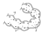
この帯電ガン10は、図2に示すように、外筒11と、当該外筒11内に設けられ、粉末潤滑剤Jが内部を輸送される筒状の摩擦体12とを有し、輸送される粉末潤滑剤Jを摩擦体12の内周面と接触摩擦し、静電気的に帯電させるものである。
As shown in FIG. 2, the
粉末潤滑剤Jと摩擦体12は、静電気的な特性(たとえば、摩擦帯電電位の序列)を考慮して材質などを決定することが望ましいが、具体例としては、粉末潤滑剤Jが前述したような金属ステアレイトであれば、摩擦体12は、フッ素樹脂製のものとすることが望ましい。このようにすれば、摩擦帯電により一方の粉末潤滑剤Jはプラスに帯電し、他方の摩擦体12はマイナスに帯電する。
It is desirable to determine the material of the powder lubricant J and the
この摩擦体12全体は、外筒11内に設けられているが、摩擦体12の下端は外筒11の噴射ノズル13に、摩擦体12の上端は粉末潤滑剤Jが導入される大径の導入チャンバ14にそれぞれ連通され、内部を輸送される粉末潤滑剤Jが内壁と接触摩擦し、静電気的に帯電させる帯電部Tとなっている。
The
この導入チャンバ14の上端部には、圧縮エアー供給部15(図1参照)からの圧縮エアーが導かれるエアー導管16と、潤滑剤供給部17(図1参照)からの粉末潤滑剤Jが輸送される潤滑剤導管18が連通され、導入チャンバ14内で圧縮エアーと粉末潤滑剤Jがミックスされる。なお、前記圧縮エアーは、粉末潤滑剤Jとのミックス性を考慮すれば、乾燥剤などにより水分を吸着除去した乾燥エアーであることが好ましい。
An
導入チャンバ14は、大径部から漏斗状に絞った形状とすることが好ましい。このようにすれば、輸送されてきた粉末潤滑剤Jが大径部で十分拡散された後に、摩擦体12に流入する直前に喉部19で絞られ、ここでの粉末潤滑剤Jの流速がさらに高められた状態で摩擦体12内に噴射されることになる。この結果、粉末潤滑剤Jが摩擦体12の内壁に衝突する力が高まり、大きな摩擦力が生じ、粉末潤滑剤Jの帯電量を増大させることができる。なお、潤滑剤供給部17としては、タンク内に貯留された粉末潤滑剤Jを攪拌器などにより浮遊状態とし、サイクロンなどにより吸引し、排出するものである。
It is preferable that the
また、摩擦体12は、螺旋状に外筒11内に設けられている。このように螺旋状にすれば、外筒11内に長尺な摩擦体12を設置でき、実質的に帯電部Tの長さが長くなり、外筒11の軸方向長さを短くしても、帯電能力が低下することはなく、コンパクトで優れた帯電性能を発揮する帯電ガン10となる。
The
摩擦体12に関しても、図3に示すように、当該摩擦体12の軸線方向に沿う半断面形状を波形状とすることが好ましい。ここに、「波形状」とは、凹凸状、ジグザグ状など種々の形状を含むもので、摩擦体12内の粉末潤滑剤Jが摩擦体12の内周面の接しつつ滞留あるいは停止することなく円滑に輸送される形状であればよい。このようにすれば、輸送途中に粉末潤滑剤Jが摩擦体12の内壁と接触摩擦する機会が多くなり、より強力にプラスに帯電させることができる。
As for the
特に、本実施形態では、静電気的に帯電した粉末潤滑剤Jが前記キャビティの側面Ca、即ち重力方向での側面にクーロン力で強固に付着するように、ダイ1に電場降下手段Dが設けられている。
In particular, in this embodiment, the electric field lowering means D is provided on the
帯電ガン10より噴射された粉末潤滑剤Jは、重力の影響を受け、キャビティCの重力方向側面には付着しにくく、落下し、下ポンチ3の上面3aに溜まるが、ダイ1の電場強度を下げ、キャビティの側面Caをマイナスにすると、プラスに帯電した粉末潤滑剤Jが重力の影響を受けても大きなクーロン力でキャビティの側面Caに強固に付着し、粉末潤滑剤Jが下ポンチ3の上面3aに溜まることがない。
The powder lubricant J sprayed from the charging
この電場降下手段Dは、ダイ1の電場強度を下げることができるものであればどのようなものであってもよいが、本実施形態では、導電体により形成されたダイ1に導電線20の一端を接続し、当該導電線20の他端を電気的に接地(アース)することにより構成している。つまり、キャビティの重力方向側面が保有する電場強度をゼロにすると、帯電した粉末潤滑剤Jとキャビティの側面Caとの間に働く電場の強度が高められることになり、大きなクーロン力が作用し、粉末潤滑剤の付着力が高まる。
The electric field lowering means D may be anything as long as the electric field strength of the
さらに、下ポンチ3の上面3a(キャビティ面)や上ポンチ2の下面2a(キャビティ面)を電気的絶縁コーティングすると、ダイ1の粉末潤滑剤Jを引き付ける電場強度が、下ポンチ3の上面3aや上ポンチ2の下面2aの粉末潤滑剤Jを引き付ける電場強度よりも大きくなるため、下ポンチ3や上ポンチ2が粉末潤滑剤Jを引き付けたり、あるいはダイ1の引き付けを邪魔することがなく、よりダイ1のキャビティの側面Caに粉末潤滑剤Jが付着し易くなる。これにより、効率的に粉末潤滑剤Jを所望の部位に塗布し付着させることができ、成形時の摩擦力を低減でき、高圧成形が実現できる。
Further, when the
次に、粉末潤滑剤の塗布方法を説明する。 Next, a method for applying the powder lubricant will be described.
図4は粉末潤滑剤の塗布状態を示す概略断面図、図5は成形粉末の充填状態を示す概略断面図、図6は成形粉末の圧縮成形状態を示す概略断面図である。
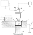
<粉末潤滑剤の塗布>
図4において、キャビティC内で成形粉末Fを圧縮成形する前に、電場降下手段Dによりダイ1を電気的に接地し、ダイ1の電場強度を下げた状態にし、帯電ガン10によりキャビティC内に帯電された粉末潤滑剤Jを塗布する。
FIG. 4 is a schematic cross-sectional view showing the application state of the powder lubricant, FIG. 5 is a schematic cross-sectional view showing the filling state of the molding powder, and FIG. 6 is a schematic cross-sectional view showing the compression molding state of the molding powder.
<Application of powder lubricant>
In FIG. 4, before compression molding the molding powder F in the cavity C, the
この粉末潤滑剤Jの塗布は、まず、帯電ガン10をダイ1のキャビティC直上にセットし、キャビティCの下部には、上面3aに電気的絶縁コーティングHが施された下ポンチ3を配置する。そして、圧縮エアー供給部15と潤滑剤供給部17を作動し、圧縮エアー供給部15からの圧縮エアーをエアー導管16より帯電ガン10の導入チャンバ14に導き、潤滑剤供給部17からの粉末潤滑剤Jも潤滑剤導管18より帯電ガン10の導入チャンバ14に輸送する。
In applying the powder lubricant J, first, the charging
導入チャンバ14内では、圧縮エアーにより粉末潤滑剤Jが分散され、粉末潤滑剤Jを含む混合気流となって摩擦体12に流入するが、この混合気流は、喉部19により絞られるので、ここで流速が高められ、摩擦体12内に高速で噴射される。
In the
摩擦体12に入った混合気流は、摩擦体12に沿って流過するが、摩擦体12が螺旋状に形成され、しかも、摩擦体12の内周面が波形状になっているので、個々の粉末潤滑剤Jは、単に摩擦体12内を通過することはなく、摩擦体12の内壁と接触摩擦する回数や、摩擦体12の内壁と衝突する回数が大幅に増大し、摩擦体12の内壁との間で大きな摩擦力を受けて流れる。したがって、粉末潤滑剤Jは、帯電した個数の増大あるいは各潤滑剤粉末Jが保有する帯電量も増大する。
The mixed airflow that has entered the
このようにして強力にプラスに帯電した粉末潤滑剤Jは、噴射ノズル13からキャビティCに向って噴射されるが、キャビティCにおいては、側面Caの電場強度が低下した状態であるため、噴射された粉末潤滑剤Jは、重力に影響されることなくキャビティの側面Caに強力に付着することになる。また、下ポンチ3の上面3aも電気的絶縁コーティングHが施されているので、下ポンチ3がダイ1の引き付けを邪魔することはなく、よりダイ1のキャビティの側面Caに粉末潤滑剤Jが付着し易くなる。
The powder lubricant J that is strongly positively charged in this way is injected from the
したがって、キャビティの側面Caにより多量の粉末潤滑剤Jが付着し、下ポンチ3の上面3aに落下する粉末潤滑剤Jの量が減り、キャビティCの内面に付着する粉末潤滑剤Jは、キャビティCの内面全体に適度に行き渡る。
<成形粉末の充填>
この状態で、図5に示すように、フィードシュー4をキャビティCの上部まで移動し、内部の成形粉末FをキャビティC内に投入すると、成形粉末Fは、粉末潤滑剤Jにより内周面が覆われた状態のキャビティC内に充填される。
<圧縮成形>
この充填後、図6に示すように、キャビティCの上部に上ポンチ2を移動し、常法により上ポンチ2と下ポンチ3との共働でキャビティC内の成形粉末Fを圧縮成形する。
Therefore, a large amount of the powder lubricant J adheres to the side surface Ca of the cavity, the amount of the powder lubricant J that falls on the
<Filling of molding powder>
In this state, as shown in FIG. 5, when the
<Compression molding>
After this filling, as shown in FIG. 6, the
この圧縮成形時において、下ポンチ3の上面3aには余分な粉末潤滑剤Jが付着していないので、キャビティC内で成形された成形物は、成形面の面粗度や寸法精度が向上したものが得られる。
<成形物の取り出し>
圧縮成形後、上ポンチ2をキャビティC内から外方に後退し、下ポンチ3を上方に移動すると、粉末潤滑剤Jの存在により成形物はキャビティC内から外方に円滑に取り出すことができる。
At the time of this compression molding, since the excess powder lubricant J does not adhere to the
<Removal of molded product>
After compression molding, when the
このように本実施形態では、キャビティC内で成形粉末Fを圧縮成形する前に、ダイ1の電場強度を下げた後、帯電ガン10より粉末潤滑剤Jを塗布するので、重力に影響されることなく粉末潤滑剤Jをキャビティの側面Caに付着させることができ、キャビティ内の粉末潤滑剤JをキャビティCの内面全体に適度に行き渡らせることができ、しかも、従来装置のように種々の面倒な制御も必要としないため、作業性やコストの面でも有利となる。また、電場強度の下げに関しても、ダイ1を導電体とし、これを電気的に接地するのみであるため、この点でも作業性やコストの面で有利となる。しかも、下ポンチ3の上面3aを電気的絶縁コーティングすれば、ダイ1の電場強度を下げる場合でも、下ポンチ3が悪影響せず、より強力な粉末潤滑剤Jの付着が可能になる。
As described above, in this embodiment, the powder lubricant J is applied from the charging
このように粉末潤滑剤Jの強力な付着により下ポンチ3の上面3aに余分な粉末潤滑剤Jが付着しないため、成形物の面粗度や寸法精度も向上する。
As described above, since the excessive powder lubricant J does not adhere to the
帯電ガン10に関しても、粉末潤滑剤Jが内部を輸送される摩擦体12を外筒11内で螺旋状に設けると、帯電を行なう部分の実質的な長さが長くなるにも拘らず、全体形状が小さく、扱い易いものとすることができる。また、摩擦体12の軸線方向に沿う半断面形状を波形状とすれば、輸送中の粉末潤滑剤Jが摩擦体12の内壁と接触摩擦する機会が多くなり、より強力に帯電させることができる。しかも、輸送された粉末潤滑剤が摩擦体12に流入する直前に喉部19を設けると、粉末潤滑剤Jが高速で摩擦体12に噴射され、摩擦体12の内壁に衝突する力が上がり、大きな摩擦力が生じ、粉末潤滑剤Jをより強力に帯電させることができる。
With respect to the charging
なお、本発明は上述した実施の形態に限定されるものではなく、特許請求の範囲内で種々改変することができる。例えば、前記実施形態では、摩擦体は、管体自体軸方向に膨出縮小して波形状としているが、これのみでなく少なくとも内面が軸方向に沿って波形状であればよい。また、前記実施形態では、便宜的にキャビティCが円柱形状をしたものとしたので、キャビティの側面Caも円弧状をしたものとなるが、たとえば、圧縮成形するものが歯車であれば、キャビティの側面Caは凹凸状となることもあり、キャビティの側面Caの形状は、種々の形状となることはいうまでもない。 The present invention is not limited to the above-described embodiment, and various modifications can be made within the scope of the claims. For example, in the above-described embodiment, the friction body bulges and contracts in the axial direction of the tube itself to have a wave shape. However, not only this but at least the inner surface may have a wave shape along the axial direction. In the above embodiment, the cavity C has a cylindrical shape for convenience. Therefore, the side surface Ca of the cavity also has an arc shape. For example, if the object to be compression-molded is a gear, Needless to say, the side surface Ca may be uneven, and the shape of the side surface Ca of the cavity may be various shapes.
本発明にかかる粉末潤滑剤の塗布方法と装置は、コンロッド、スプロケット、歯車などの自動車用の部品を成形粉末により圧縮して焼結する場合に使用される粉末潤滑剤の塗布に適している。 The method and apparatus for applying a powder lubricant according to the present invention is suitable for application of a powder lubricant used in the case of compressing and sintering automotive parts such as connecting rods, sprockets, and gears with molding powder.
1…ダイ(成形型)、
2…上ポンチ(上部加圧体)、
2a…上ポンチの下面(キャビティ面)、
3…下ポンチ(下部加圧体)、
3a…下ポンチの上面(キャビティ面)、
10…帯電ガン、
11…外筒、
12…摩擦体、
C…キャビティ、
Ca…キャビティの側面、
D…電場降下手段、
F…成形粉末、
H…電気的絶縁コーティング、
J…粉末潤滑剤。
1 ... Die (mold)
2 ... Upper punch (upper pressure body),
2a: The lower surface (cavity surface) of the upper punch,
3 ... Lower punch (lower pressure body),
3a: The upper surface (cavity surface) of the lower punch,
10 ... Charging gun,
11 ... outer cylinder,
12 ... friction body,
C ... cavity,
Ca ... the side of the cavity,
D: Electric field drop means,
F ... Molded powder,
H ... Electrical insulation coating,
J: Powder lubricant.
Claims (7)
Priority Applications (1)
| Application Number | Priority Date | Filing Date | Title |
|---|---|---|---|
| JP2004110440A JP2005290518A (en) | 2004-04-02 | 2004-04-02 | Method and apparatus for applying powder lubricant |
Applications Claiming Priority (1)
| Application Number | Priority Date | Filing Date | Title |
|---|---|---|---|
| JP2004110440A JP2005290518A (en) | 2004-04-02 | 2004-04-02 | Method and apparatus for applying powder lubricant |
Publications (1)
| Publication Number | Publication Date |
|---|---|
| JP2005290518A true JP2005290518A (en) | 2005-10-20 |
Family
ID=35323781
Family Applications (1)
| Application Number | Title | Priority Date | Filing Date |
|---|---|---|---|
| JP2004110440A Pending JP2005290518A (en) | 2004-04-02 | 2004-04-02 | Method and apparatus for applying powder lubricant |
Country Status (1)
| Country | Link |
|---|---|
| JP (1) | JP2005290518A (en) |
Cited By (4)
| Publication number | Priority date | Publication date | Assignee | Title |
|---|---|---|---|---|
| JP2009006374A (en) * | 2007-06-28 | 2009-01-15 | Kobe Steel Ltd | Compacting method of large-sized high-density green compact |
| JP2015063722A (en) * | 2013-09-24 | 2015-04-09 | トヨタ自動車株式会社 | Iron powder molding method |
| JP2015131983A (en) * | 2014-01-10 | 2015-07-23 | トヨタ自動車株式会社 | iron powder molding method |
| US20170232519A1 (en) * | 2014-09-17 | 2017-08-17 | Kabushiki Kaisha Toshiba | Nozzle and additive manufacturing apparatus |
-
2004
- 2004-04-02 JP JP2004110440A patent/JP2005290518A/en active Pending
Cited By (5)
| Publication number | Priority date | Publication date | Assignee | Title |
|---|---|---|---|---|
| JP2009006374A (en) * | 2007-06-28 | 2009-01-15 | Kobe Steel Ltd | Compacting method of large-sized high-density green compact |
| JP2015063722A (en) * | 2013-09-24 | 2015-04-09 | トヨタ自動車株式会社 | Iron powder molding method |
| JP2015131983A (en) * | 2014-01-10 | 2015-07-23 | トヨタ自動車株式会社 | iron powder molding method |
| US20170232519A1 (en) * | 2014-09-17 | 2017-08-17 | Kabushiki Kaisha Toshiba | Nozzle and additive manufacturing apparatus |
| US10974320B2 (en) | 2014-09-17 | 2021-04-13 | Kabushiki Kaisha Toshiba | Nozzle and additive manufacturing apparatus |
Similar Documents
| Publication | Publication Date | Title |
|---|---|---|
| CA1050261A (en) | Apparatus for lubricating moulds for blanks | |
| US7041336B2 (en) | Intermittent coating apparatus and intermittent coating method | |
| KR101369846B1 (en) | Dispenser type nozzle device | |
| CN103999175A (en) | Molding method for molded powder compact | |
| JP2005290518A (en) | Method and apparatus for applying powder lubricant | |
| ATE337872T1 (en) | PRODUCTION PROCESS FOR POWDER GREEN BODY | |
| CN1115968A (en) | Method and device for applying a lubricant carrier layer, in particular to a wire-drawn material to be formed in a wire-drawing process | |
| CN1139481C (en) | Powder compression molding method, molding machine and dry battery | |
| JP3383731B2 (en) | Powder metallurgy apparatus and method using electrostatic die wall lubrication | |
| CN105393005A (en) | Sintered bearing and process for producing same | |
| US5437545A (en) | Method and apparatus for extruding powdered material | |
| EP1407841A3 (en) | Method and apparatus for manufacturing billets for thixocasting | |
| JP2003519037A (en) | Manufacturing method of ceramic tube with radial preferential direction | |
| JP5871777B2 (en) | Battery manufacturing method and apparatus | |
| US20030228423A1 (en) | Method of manufacturing a friction plate | |
| JP3779557B2 (en) | Lubricant coating device for powder molding dies | |
| JP2009034715A (en) | Powder molding die and method of filling powder into the powder molding die | |
| JPH07116490B2 (en) | Manufacturing method of sintered bearing material | |
| CN116727667A (en) | Powder metallurgy forming die | |
| JP2015044156A (en) | Kneading device of electrode paste | |
| JPH11140505A (en) | Powder molding method in powder metallurgy | |
| JPH091308A (en) | Mold release agent coating particles for mold and method for applying mold release agent | |
| US20080271951A1 (en) | Method for dispensing lubricants, and gas production element for carrying out the method | |
| JPS62101404A (en) | Extruder for slurry | |
| KR101799498B1 (en) | Powder Forming Mold Possible Supply of Lubricant and Powder Molding Method Using it |
Legal Events
| Date | Code | Title | Description |
|---|---|---|---|
| A621 | Written request for application examination |
Effective date: 20070226 Free format text: JAPANESE INTERMEDIATE CODE: A621 |
|
| A977 | Report on retrieval |
Free format text: JAPANESE INTERMEDIATE CODE: A971007 Effective date: 20081224 |
|
| A131 | Notification of reasons for refusal |
Effective date: 20090203 Free format text: JAPANESE INTERMEDIATE CODE: A131 |
|
| A02 | Decision of refusal |
Effective date: 20090602 Free format text: JAPANESE INTERMEDIATE CODE: A02 |