JP2005288664A - Polishing device and method for detecting completion of polishing pad standing - Google Patents
Polishing device and method for detecting completion of polishing pad standing Download PDFInfo
- Publication number
- JP2005288664A JP2005288664A JP2004111510A JP2004111510A JP2005288664A JP 2005288664 A JP2005288664 A JP 2005288664A JP 2004111510 A JP2004111510 A JP 2004111510A JP 2004111510 A JP2004111510 A JP 2004111510A JP 2005288664 A JP2005288664 A JP 2005288664A
- Authority
- JP
- Japan
- Prior art keywords
- polishing
- polishing pad
- polished
- pad
- completion
- Prior art date
- Legal status (The legal status is an assumption and is not a legal conclusion. Google has not performed a legal analysis and makes no representation as to the accuracy of the status listed.)
- Pending
Links
Images


Classifications
-
- B—PERFORMING OPERATIONS; TRANSPORTING
- B24—GRINDING; POLISHING
- B24B—MACHINES, DEVICES, OR PROCESSES FOR GRINDING OR POLISHING; DRESSING OR CONDITIONING OF ABRADING SURFACES; FEEDING OF GRINDING, POLISHING, OR LAPPING AGENTS
- B24B53/00—Devices or means for dressing or conditioning abrasive surfaces
- B24B53/017—Devices or means for dressing, cleaning or otherwise conditioning lapping tools
-
- B—PERFORMING OPERATIONS; TRANSPORTING
- B24—GRINDING; POLISHING
- B24B—MACHINES, DEVICES, OR PROCESSES FOR GRINDING OR POLISHING; DRESSING OR CONDITIONING OF ABRADING SURFACES; FEEDING OF GRINDING, POLISHING, OR LAPPING AGENTS
- B24B49/00—Measuring or gauging equipment for controlling the feed movement of the grinding tool or work; Arrangements of indicating or measuring equipment, e.g. for indicating the start of the grinding operation
- B24B49/10—Measuring or gauging equipment for controlling the feed movement of the grinding tool or work; Arrangements of indicating or measuring equipment, e.g. for indicating the start of the grinding operation involving electrical means
Abstract
Description
本発明は、SOI(Silicon on Insulator)ウエハや、ベアシリコンウエハ、或いは酸化膜ウエハ等の被研磨基板を研磨する研磨装置に関し、特に研磨装置の研磨テーブル上面に貼り付けた研磨パッドの状態を検知する研磨パッド状態検知手段を具備する研磨装置、及び研磨パッドの立上完了を検知する研磨パッド立上完了検知方法に関するものである。 The present invention relates to a polishing apparatus for polishing a substrate to be polished such as an SOI (Silicon on Insulator) wafer, a bare silicon wafer, or an oxide film wafer, and particularly detects the state of a polishing pad attached to the upper surface of a polishing table of the polishing apparatus. The present invention relates to a polishing apparatus including a polishing pad state detection means, and a polishing pad rising completion detection method for detecting completion of polishing pad rising.
SOIウエハや、ベアシリコンウエハ、或いは酸化膜ウエハ等の被研磨基板を研磨する研磨装置としては、研磨テーブル上面に軟質発泡ウレタンパッド等の研磨パッドを貼付し、トップリングで保持し回転する被研磨基板を回転する研磨テーブルの研磨パッドに当接し、押圧することにより該被研磨基板と研磨パッドの相対的運動により被研磨基板の研磨を行なう研磨装置がある。このような研磨装置において、新しく研磨パッドを研磨テーブル上面に貼り付けて研磨を行う際には、研磨に先駆けて研磨パッドの立上げ作業を行わなくてはならない。これは、主に上記軟質発泡ウレタンパッド等の研磨パッドの最上層には保護膜が形成されており、研磨に際してこの保護膜を除去する必要があることによる。
従来、上記研磨パッドの立上げ作業は、ダミーウエハを予め設定した枚数(3〜80枚程度)研磨し、その後モニター用ウエハを研磨して研磨レートや研磨表面精度を測定し、研磨パッドの立上げ完了を判断していた。しかし、研磨パッドの立上げ完了のタイミングは、作業者の経験によるところが大きく、定量的判断は不可能であった。また、研磨パッドの品質のバラツキ等による立上げ時間のバラツキを考慮して、実質の立上げに必要な時間以上の時間を使って研磨パッドの立上げ作業を行っていた。なお、半導体ウエハの研磨終点を検知する終点検知方法としては、上記特許文献1に記載されたものがあるが、これは被研磨基板の研磨終点を検知するもので、研磨パッドの立上げ完了を検知するものではない。
Conventionally, the polishing pad is started up by polishing a predetermined number of dummy wafers (about 3 to 80), and then polishing the monitor wafer and measuring the polishing rate and the polishing surface accuracy to start up the polishing pad. Judging completion. However, the timing of completion of starting up the polishing pad largely depends on the experience of the operator, and quantitative judgment is impossible. Further, in consideration of variations in the startup time due to variations in the quality of the polishing pad, the polishing pad has been started up using a time longer than the time required for actual startup. In addition, as an end point detection method for detecting the polishing end point of the semiconductor wafer, there is a method described in
本発明は上述の点に鑑みてなされたもので、研磨パッドの立上げ完了を定量的に判断できる研磨装置、及び研磨パッド立上完了検知方法を提供することを目的とする。 The present invention has been made in view of the above points, and an object of the present invention is to provide a polishing apparatus and a polishing pad start-up completion detection method capable of quantitatively determining completion of polishing pad startup.
請求項1に記載の発明は、上面に研磨パッドが貼り付けられた研磨テーブルと、該研磨テーブルを駆動する研磨テーブル駆動部と、被研磨物を保持し該被研磨物の被研磨面を研磨パッドに当接・押圧する保持器と、該保持器を駆動する保持器駆動部を具備する研磨装置であって、保持器駆動部及び/又は研磨テーブル駆動部の駆動電流値を検出する電流センサを設け、ダミー被研磨物を研磨パッドに当接・押圧し、該ダミー被研磨物と研磨パッドの相対的運動によりダミー被研磨物を研磨し、電流センサが検出した保持器駆動部及び/又は研磨テーブル駆動部の駆動電流から研磨パッドの状態を検知する研磨パッド状態検知手段を設けたことを特徴とする。 According to the first aspect of the present invention, a polishing table having a polishing pad attached to the upper surface, a polishing table driving unit that drives the polishing table, and a polishing target surface that holds the object to be polished and polishes the surface to be polished of the object to be polished A polishing apparatus comprising a cage that contacts and presses against a pad and a cage driving unit that drives the cage, and a current sensor that detects a driving current value of the cage driving unit and / or the polishing table driving unit The dummy polishing object is brought into contact with and pressed against the polishing pad, the dummy polishing object is polished by the relative movement of the dummy polishing object and the polishing pad, and the cage driving unit detected by the current sensor and / or A polishing pad state detecting means for detecting the state of the polishing pad from the driving current of the polishing table driving unit is provided.
請求項2に記載の発明は、請求項1に記載の研磨装置において、研磨パッドを研磨テーブル上面に貼り付けた際の研磨パッドの立上げ工程にダミー被研磨物を研磨し、研磨パッド状態検知手段は電流センサが検出した電流から研磨パッドの立上げ完了を検知することを特徴とする。 According to a second aspect of the present invention, in the polishing apparatus according to the first aspect, the polishing object is polished in the step of starting up the polishing pad when the polishing pad is attached to the upper surface of the polishing table, and the state of the polishing pad is detected. The means is characterized in that the completion of the polishing pad startup is detected from the current detected by the current sensor.
請求項3に記載の発明は、請求項2に記載の研磨装置において、研磨パッド状態検知手段は、電流センサが検出した電流値を所定の閾値と比較し、該電流値が該閾値に達したとき、研磨パッドの立上げ完了とすることを特徴とする。 According to a third aspect of the present invention, in the polishing apparatus according to the second aspect, the polishing pad state detection means compares the current value detected by the current sensor with a predetermined threshold value, and the current value has reached the threshold value. In some cases, the start-up of the polishing pad is completed.
請求項4に記載の発明は、請求項1乃至3のいずれか1項に記載の研磨装置において、研磨パッド状態検知手段は研磨パッドの立上げ完了を検知すると、該立上げ完了信号を該研磨装置を管理制御する制御装置に伝送することを特徴とする。 According to a fourth aspect of the present invention, in the polishing apparatus according to any one of the first to third aspects, when the polishing pad state detection means detects the completion of the polishing pad startup, the polishing completion signal is sent to the polishing completion signal. It transmits to the control apparatus which manages and controls an apparatus.
請求項5に記載の発明は、研磨装置の研磨テーブル上面に貼り付けられた研磨パッドの立上げ完了を検知する研磨パッド立上完了検知方法であって、研磨パッドに保持器で保持されたダミー被研磨物を当接・押圧し、該被研磨物と研磨パッドの相対的運動によりダミー被研磨物を研磨し、保持器を駆動する保持器駆動部及び/又は研磨テーブルを駆動する研磨テーブル駆動部の駆動電流値から、研磨パッド立上完了を検知することを特徴とする研磨パッド立上完了検知方法にある。
The invention according to
請求項6に記載の発明は、請求項5に記載の研磨パッド立上完了検知方法において、保持器駆動部及び/又は研磨テーブル駆動部の駆動電流値を所定の閾値と比較し、該駆動電流値が該閾値に達したとき研磨パッドの立上げ完了を検知することを特徴とする。 According to a sixth aspect of the present invention, in the polishing pad start-up completion detection method according to the fifth aspect, the driving current value of the cage driving unit and / or the polishing table driving unit is compared with a predetermined threshold value, and the driving current is determined. When the value reaches the threshold value, completion of the polishing pad startup is detected.
軟質発泡ウレタンパッド等の研磨パッドの最上層には保護膜が形成されており、新しく研磨パッドを研磨テーブル上面に貼り付けて、保持器で保持するダミー被研磨物を該研磨パッドに当接・押圧して研磨すると、最上層の保護膜が研磨除去される前と後では被研磨物と研磨パッドの間の摩擦力が異なり、これにより保持器を駆動する駆動部及び/又は研磨テーブルを駆動する駆動部の駆動電流も異なる。従って、保持器駆動部及び/又は研磨テーブル駆動部の駆動電流を検出する電流センサを設け、該電流センサで検出した電流値を研磨パッドの最上層の保護膜が除去された時、即ち研磨パッド立上完了の電流値(閾値)と比較し、該検出電流値が閾値に達したとき、研磨パッド立上完了と判断する。 A protective film is formed on the uppermost layer of the polishing pad such as a soft urethane foam pad. A new polishing pad is affixed to the upper surface of the polishing table, and a dummy object to be held by a cage is brought into contact with the polishing pad. When pressed and polished, the frictional force between the object to be polished and the polishing pad is different before and after the uppermost protective film is removed by polishing, thereby driving the drive unit and / or the polishing table that drives the cage. The driving current of the driving unit to be different is also different. Accordingly, a current sensor for detecting the drive current of the cage driving unit and / or the polishing table driving unit is provided, and the current value detected by the current sensor is detected when the uppermost protective film of the polishing pad is removed, that is, the polishing pad. Compared with the current value (threshold value) of the completion of startup, when the detected current value reaches the threshold value, it is determined that the polishing pad startup is completed.
請求項1に記載の発明によれば、電流センサが検出した保持器駆動部及び/又は研磨テーブル駆動部の駆動電流から研磨パッドの状態を検知する研磨パッド状態検知手段を設けたので、研磨パッドの状態、即ち研磨パッドの最上層の保護膜が除去されたか否か、被研磨物を研磨できる状態になった否かを検出できる研磨装置を提供できる。 According to the first aspect of the present invention, since the polishing pad state detecting means for detecting the state of the polishing pad is provided from the driving current of the cage driving unit and / or the polishing table driving unit detected by the current sensor, the polishing pad is provided. In other words, it is possible to provide a polishing apparatus capable of detecting the above state, that is, whether or not the uppermost protective film of the polishing pad has been removed, and whether or not the object to be polished can be polished.
請求項2に記載の発明によれば、研磨パッドを研磨テーブルの上面に貼り付けた際の研磨パッドの立上げ工程にダミー被研磨物を研磨し、研磨パッド状態検知手段は電流センサが検出した電流値から研磨パッドの立上げ完了を検知するので、研磨パッド立上げ完了を定量的に検知できる。 According to the second aspect of the present invention, the dummy polishing object is polished in the polishing pad startup process when the polishing pad is attached to the upper surface of the polishing table, and the current sensor detects the polishing pad state detection means. Since the completion of the polishing pad startup is detected from the current value, the polishing pad startup completion can be quantitatively detected.
請求項3に記載の発明によれば、研磨パッド状態検知手段は、電流センサが検出した電流値を所定の閾値と比較し、該電流値が該閾値に達したとき、研磨パッドの立上げ完了とするので、この閾値の値を研磨パッドの最上層の保護膜が除去された時の駆動電流値に設定しておくと、精度よく研磨パッドの立上げ完了を検知できる。従って、無駄に研磨パッドを摩耗させたり、研磨パットが研磨できる状態になる前に被研磨物を研磨したりすることがなくなる。 According to the invention described in claim 3, the polishing pad state detection means compares the current value detected by the current sensor with a predetermined threshold value, and when the current value reaches the threshold value, the polishing pad start-up is completed. Therefore, if the threshold value is set to the drive current value when the uppermost protective film of the polishing pad is removed, the completion of the polishing pad startup can be detected with high accuracy. Therefore, the polishing pad is not wasted and the object to be polished is not polished before the polishing pad can be polished.
請求項4に記載の発明によれば、研磨パッド状態検知手段は研磨パッドの立上げ完了を検知すると、該立上げ完了信号を該研磨装置を制御する制御装置に伝送するので、制御装置は研磨パッドの立上げ完了に対応して研磨装置を管理制御でき、研磨装置の運転効率等を向上させることができる研磨パッド立上完了検知方法を提供できる。 According to the fourth aspect of the present invention, when the polishing pad state detection means detects the completion of the polishing pad startup, it transmits the startup completion signal to the control device that controls the polishing device. It is possible to provide a polishing pad start-up completion detection method that can manage and control the polishing apparatus in response to the completion of the pad startup and can improve the operation efficiency of the polishing apparatus.
請求項5に記載の発明によれば、保持器を駆動する保持器駆動部及び/又は研磨テーブルを駆動する研磨テーブル駆動部の駆動電流値から、研磨パッド立上完了を検知するので、研磨パッド立上げ完了を定量的に検出できる。 According to the fifth aspect of the present invention, the polishing pad rising completion is detected from the drive current value of the cage driving unit that drives the cage and / or the polishing table driving unit that drives the polishing table. The completion of start-up can be detected quantitatively.
請求項6に記載の発明によれば、保持器駆動部及び/又は研磨テーブル駆動部の駆動電流値を所定の閾値と比較し、該駆動電流値が該閾値に達したとき研磨パッドの立上げ完了を検知するので、閾値の値を研磨パッドの最上層の保護膜が除去された時の値に設定しておくと、精度よく研磨パッドの立上げ完了を検知できる。また、無駄に研磨パッドを摩耗させたり、研磨パッドが研磨できる状態になる前に被研磨物を研磨したりすることがなくなる。 According to the sixth aspect of the present invention, the driving current value of the cage driving unit and / or the polishing table driving unit is compared with a predetermined threshold value, and when the driving current value reaches the threshold value, the polishing pad is started up. Since completion is detected, if the threshold value is set to a value when the uppermost protective film of the polishing pad is removed, it is possible to accurately detect the completion of the polishing pad startup. Further, the polishing pad is not wastedly worn, and the object to be polished is not polished before the polishing pad becomes ready for polishing.
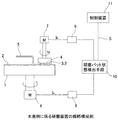
以下、本発明の実施の形態例を図面に基づいて説明する。図1は本発明に係る研磨装置の概略構成例を示す図である。研磨装置は、上面に研磨パッド2を貼り付けた研磨テーブル1を備え、該研磨テーブル1は研磨テーブル駆動部6で回転されるようになっている。4はSOIウエハや、ベアシリコンウエハ、或いは酸化膜ウエハ等の被研磨基板3を保持する保持器としてのトップリングであり、該トップリング4はトップリング駆動部7で回転されるようになっている。
Embodiments of the present invention will be described below with reference to the drawings. FIG. 1 is a diagram showing a schematic configuration example of a polishing apparatus according to the present invention. The polishing apparatus includes a polishing table 1 having a
上記構成の研磨装置において、砥液供給ノズル5から研磨パッド2に砥液(スラリー液)を供給しながら、トップリング4をトップリング駆動部7により回転させ、該トップリング4に保持される被研磨基板3を研磨テーブル駆動部6により回転する研磨テーブル1の研磨パッド2の面上に当接・押圧し、被研磨基板3と研磨パッド2の相対的運動により被研磨基板3を研磨する。
In the polishing apparatus having the above-described configuration, the top ring 4 is rotated by the top
この研磨装置において、新しく研磨パッド2を研磨テーブル1の上面に貼り付けて研磨を行う際には、研磨に先駆けて研磨パッド2の立上げ作業を行わなくてはならない。これは、上記のように軟質発泡ウレタンパッド等の研磨パッド2では、図2に示すように研磨パット本体層2−1の最上層に保護膜2−2が形成されており、研磨に際してこの保護膜2−2を除去する必要があるからである。この保護膜2−2を除去するには、研磨テーブル1の上面に新しく研磨パッド2を貼り付けた際、該研磨パッド2にトップリング4に保持されたダミー被研磨基板3’を当接・押圧して研磨を行なう。即ち、トップリング4の回転と研磨テーブル1の回転によるダミー被研磨基板3’と研磨パッド2との相対的運動により、保護膜2−2を研磨して除去する。
In this polishing apparatus, when a
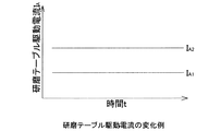
上記のようにダミー被研磨基板3’を新しく研磨パッド2に当接・押圧して研磨すると、最初は保護膜2−2とダミー被研磨基板3’との間に摩擦力F1が作用する。該保護膜2−2が研磨され除去されると、研磨パッド本体層2−1とダミー被研磨基板3’との間に摩擦力F2が作用することになる。そして、摩擦力F1と摩擦力F2の間に差がある(F1<F2)から、ダミー被研磨基板3’との当接が保護膜2−2から研磨パッド本体層2−1に変わると、研磨テーブル1を駆動する研磨テーブル駆動部6の駆動電流(モータ駆動電流)が変化する。また、同じようにトップリング4を駆動するトップリング駆動部7の駆動電流(モータ駆動電流)も変化する。図3は研磨テーブル駆動電流IAの変化例を示す図である。図示するように、摩擦力Fが保護膜2−2とダミー被研磨基板3’との間の摩擦力F1のとき、即ち研磨パッド2の立上り前では、研磨テーブル駆動電流はIA1であり、摩擦力Fが研磨パッド本体層2−1とダミー被研磨基板3’との間の摩擦力F2のとき、即ち研磨パッド2での立上り完了では、研磨テーブル駆動電流はIA2である(IA1<IA2)。また、図示は省略するが、トップリング駆動電流IBも同様に変化する。
When the dummy substrate 3 ′ is newly abutted and pressed against the
図1において、8は上記研磨テーブル駆動電流IAを検出する電流センサであり、9は上記トップリング駆動電流IBを検出する電流センサである。10は電流センサ8で検出した研磨テーブル駆動電流IAと、電流センサ9で検出したトップリング駆動電流IBから、研磨パッド2の状態を検知する研磨パッド状態検知手段である。研磨パッド2の保護膜2−2とダミー被研磨基板3’との間の摩擦力F1、研磨パッド2の本体層2−1とダミー被研磨基板3’との間の摩擦力F2は、研磨パッド2の種類によって異なる。研磨テーブル1の上面に貼り付けられた研磨パッド2の種類に応じて、研磨パッド2の保護層2−2とダミー被研磨基板3’との間の摩擦力F1による研磨テーブル駆動電流IA1とトップリング駆動電流IB1、研磨パッド2の本体層2−1とダミー被研磨基板3’との間の摩擦力F2による研磨テーブル駆動電流IA2とトップリング駆動電流IB2を、閾値として研磨パッド状態検知手段10の記憶部に予め入力し記憶しておく。
In FIG. 1, 8 is a current sensor for detecting the polishing table drive current I A , and 9 is a current sensor for detecting the top ring drive current I B. A polishing pad
電流センサ8で検出した研磨テーブル駆動電流IAや電流センサ9で検出したトップリング駆動電流IBが、上記記憶部に記憶されているIA2、IB2(閾値)に達したら、研磨パッド状態検知手段10は、研磨パッド2の立上り完了と判断する。研磨パッド状態検知手段10がこの研磨パッド2の立上り完了と判断した場合は、研磨装置を制御する制御装置11に立上り完了信号Sを伝送する。これにより制御装置11は研磨テーブル駆動部6やトップリング駆動部7を制御して研磨パット2の立上げ作業を自動的に終了させる。
When the polishing table drive current I A detected by the current sensor 8 and the top ring drive current I B detected by the
研磨パッド状態検知手段10が、電流センサ8で検出した研磨テーブル駆動電流IAと、電流センサ9で検出したトップリング駆動電流IBが、上記記憶部に記憶しているIA2、IB2(閾値)に達したと判断し、研磨パッド2の立上げが終了したと判断した時点で、実際には立上げが終了していない場合には、追加研磨としてダミー被研磨基板の研磨を行う。この追加研磨終了時の研磨テーブル駆動電流IA2とトップリング駆動電流IB2を閾値として記憶部に記憶した閾値を更新することにより、より精度の高い研磨パッド2の立上げ作業を行うことができる。なお、上記実施例では研磨パッド状態検知手段10を研磨装置を制御する制御装置11と別構成としたが、電流センサ8で検出した研磨テーブル駆動電流IAや電流センサ9で検出したトップリング駆動電流IBを制御装置11に取り込み、制御装置11で研磨パッド2の立上げ完了を判断するようにしてもよい。即ち、研磨パッド状態検知手段10の機能を制御装置11に持たせてもよい。
The polishing pad state detection means 10 detects the polishing table drive current I A detected by the current sensor 8 and the top ring drive current I B detected by the
上記研磨パッド2としては、市場で入手できる種々のものがある。例えば、ロデール社製のSUBA800、IC−1000、IC−1000/SUBA400(二層クロス)、フジミインコーポレイテッド社製のSurfinxxx−5、Surfin000等がある。SUBA800、Surfinxxx−5、Surfin000は繊維をウレタン樹脂で固めた不織布であり、IC−1000は硬質の発泡ポリウレタン(単層)である。発泡ポリウレタンは、ポーラス(多孔質状)になっており、その表面に多数の微細な凹み又は孔を有している。
There are various types of
図4は本発明に係る研磨装置の全体構成例を示す図である。図4において、図1と同一符号を付した部分は同一又は相当部分を示す。以下、他の図においても同様とする。トップリング4は自在継手部12を介してトップリング駆動軸13に接続されており、該トップリング駆動軸13はトップリングヘッド14に固定されたトップリング用エアシリンダ15に連結されている。このトップリング用エアシリンダ15によってトップリング4は上下動し、トップリング4の全体を昇降させると共にトップリング本体4−1の下端に固定されたリテーナリング4−2を研磨テーブル1の研磨パッド2に押圧する。トップリング用エアシリンダ15はレギュレータR1を介して圧縮空気100に接続されており、レギュレータR1によってトップリング用エアシリンダ15に供給される加圧空気の空気圧等を調整することができる。これによりリテーナリング4−2が研磨パッド2を押圧する押圧力を調整することができる。
FIG. 4 is a diagram showing an example of the overall configuration of the polishing apparatus according to the present invention. In FIG. 4, the parts denoted by the same reference numerals as those in FIG. 1 indicate the same or corresponding parts. Hereinafter, the same applies to other drawings. The top ring 4 is connected to a top
また、トップリング駆動軸13はキー(図示せず)を介して回転筒16に連結されている。この回転筒16はその外周部にタイミングプーリ17を備えている。トップリングヘッド14にはトップリング駆動部(モータ)7が固定されており、タイミングプーリ17は、タイミングベルト18を介してトップリング駆動部7に設けられたタイミングプーリ19に接続されている。従って、トップリング駆動部7を回転駆動することによりタイミングプーリ19、タイミングベルト18、及びタイミングプーリ17を介して回転筒16及びトップリング駆動軸13が一体に回転し、トップリング4が回転する。なお、トップリングヘッド14は、フレーム(図示せず)に固定支持されたトップリングヘッドシャフト20によって旋回自在に支持されている。
The top
図5はトップリング4の構成を示す縦断面図である。本トップリング4は、内部に収容空間を有する円筒容器状のトップリング本体4−1と、該トップリング本体4−1の下端に固定されたリテーナリング4−2とを備えている。トップリング本体4−1は金属やセラミックス等の強度及び剛性が高い材料から構成されている。また、リテーナリング4−2は剛性の高い樹脂材又はセラミックス等から形成されている。 FIG. 5 is a longitudinal sectional view showing the configuration of the top ring 4. The top ring 4 includes a cylindrical container-shaped top ring main body 4-1 having a storage space inside, and a retainer ring 4-2 fixed to the lower end of the top ring main body 4-1. The top ring body 4-1 is made of a material having high strength and rigidity such as metal and ceramics. The retainer ring 4-2 is formed of a highly rigid resin material or ceramics.
トップリング本体4−1は、円筒容器状のハウジング部4−1aと、該ハウジング部4−1aの円筒部の内側に嵌合される環状の加圧シート支持部4−1bと、ハウジング部4−1aの上面の外周縁部に嵌合された環状のシール部4−1cとを備えている。トップリング本体4−1のハウジング部4−1aの下端にはリテーナリング4−2が固定されている。このリテーナリング4−2の下部は内方に突出している。なお、リテーナリング4−2をトップリング本体4−1と一体的に形成してもよい。 The top ring body 4-1 includes a cylindrical container-shaped housing part 4-1a, an annular pressure sheet support part 4-1b fitted inside the cylindrical part of the housing part 4-1a, and a housing part 4 -1a and an annular seal portion 4-1c fitted to the outer peripheral edge portion of the upper surface. A retainer ring 4-2 is fixed to the lower end of the housing part 4-1a of the top ring body 4-1. The lower part of the retainer ring 4-2 protrudes inward. The retainer ring 4-2 may be formed integrally with the top ring body 4-1.
トップリング本体4−1のハウジング部4−1aの中央部の上方には、トップリング駆動軸13が配設されており、トップリング本体4−1とトップリング駆動軸13とは自在継手12により連結されている。この自在継手12は、トップリング本体4−1及びトップリング駆動軸13とを互いに傾動可能とする球面軸受機構と、トップリング駆動軸13の回転をトップリング本体4−1に伝達する回転伝達機構とを備えており、トップリング駆動軸13からトップリング本体4−1に対して互いの傾動を許容しつつ押圧力及び回転力を伝達する。
A top
球面軸受機構は、トップリング駆動軸13の下面の中央に形成された球面状凹部13aとハウジング部4−1aの上面の中央に形成された球面状凹部4−1dと、両凹部13a、4−1d間に介装されたセラミックスのような高硬度材料からなるベアリングボール21とから構成されている。一方、回転伝達機構は、トップリング駆動軸13に固定された駆動ピン(図示せず)とハウジング部4−1aに固定された被駆動ピン(図示せず)とから構成される。トップリング本体4−1が傾いても被駆動ピンと駆動ピンとが相対的に上下方向に移動可能であるため、これらは互いの接触点をずらして係合し、回転伝達機構がトップリング駆動軸13の回転トルクをトップリング本体4−1に確実に伝達する。
The spherical bearing mechanism includes a
トップリング本体4−1及びリテーナリング4−2の内部の空間には、トップリング4によって保持される被研磨基板3に当接する弾性パッド4−3と、環状のホルダーリング4−4と、弾性パッド4−3を支持する概略円板状のチャッキングプレート4−5とが収容されている。弾性パッド4−3は、その外周部がホルダーリング4−4とその下端に固定されたチャッキングプレート4−5との間に挟み込まれており、チャッキングプレート4−5の下面を覆っている。これにより弾性パッド4−3とチャッキングプレート4−5との間には空間が形成されている。 In the space inside the top ring body 4-1 and the retainer ring 4-2, an elastic pad 4-3 that comes into contact with the substrate to be polished 3 held by the top ring 4, an annular holder ring 4-4, and elasticity A substantially disc-shaped chucking plate 4-5 that supports the pad 4-3 is accommodated. The elastic pad 4-3 is sandwiched between the holder ring 4-4 and the chucking plate 4-5 fixed to the lower end thereof, and covers the lower surface of the chucking plate 4-5. . Thereby, a space is formed between the elastic pad 4-3 and the chucking plate 4-5.
なお、チャッキングプレート4−5は金属材料から形成されているほうがよいが、研磨すべき被研磨基板(例えば半導体ウエハ)3がトップリング4に保持された状態で、渦電流を用いた膜厚測定方法でその表面に形成された薄膜の膜厚を測定する場合などについては、磁性を持たない材料、例えば、フッ素系樹脂やセラミックス等の絶縁性の材料から形成されていることが好ましい。 The chucking plate 4-5 is preferably made of a metal material, but the film thickness using eddy current in a state where the substrate to be polished 3 (for example, a semiconductor wafer) 3 to be polished is held by the top ring 4 is used. When the film thickness of the thin film formed on the surface is measured by a measurement method, it is preferable that the thin film is formed from a non-magnetic material, for example, an insulating material such as a fluororesin or ceramic.
ホルダーリング4−4とトップリング本体4−1との間には弾性膜からなる加圧シート4−6が張設されている。この加圧シート4−6は、一端をトップリング本体4−1のハウジング部4−1aと加圧シート支持部4−1bとの間に挟み込み、他端をホルダーリング4−4の上端部4−4aとストッパ部4−4bとの間に挟み込んで固定されている。トップリング本体4−1、チャッキングプレート4−5、ホルダーリング4−4、及び加圧シート4−6によってトップリング本体4−1の内部に圧力室22が形成されている。該圧力室22にはチューブ、コネクタ等からなる流体流路23が連通されており、圧力室22は流体流路23上に配置されたレギュレータR2を介して圧縮空気源100に接続されている(図4参照)。なお、加圧シート4−6は、エチレンプロピレンゴム(EPDM)、ポリウレタンゴム、シリコンゴムなどの強度及び耐久性に優れたゴム材によって形成されている。
A pressure sheet 4-6 made of an elastic film is stretched between the holder ring 4-4 and the top ring body 4-1. One end of the pressure sheet 4-6 is sandwiched between the housing part 4-1a of the top ring body 4-1 and the pressure sheet support part 4-1b, and the other end thereof is the upper end part 4 of the holder ring 4-4. -4a and the stopper portion 4-4b. A pressure chamber 22 is formed inside the top ring body 4-1 by the top ring body 4-1, the chucking plate 4-5, the holder ring 4-4, and the pressure sheet 4-6. A
トップリング本体4−1は、シール部4−1cが嵌合されるハウジング4−1aの上面の外周縁付近には、環状の溝からなる洗浄液路24が形成されている。この洗浄液路24はシール部4−1cの貫通孔25を介して流体流路26に連通しており、この流体流路26を介して洗浄液(例えば純水)が供給される。また、洗浄液路24からハウジング4−1a、加圧シート支持部4−1bを貫通する連通孔27が複数箇所設けられており、この連通孔27は弾性パッド4−3の外周面とリテーナリング4−2との間のわずかな間隙Gへ連通している。
In the top ring main body 4-1, a cleaning
弾性パッド4−3とチャッキングプレート4−5との間に形成される空間の内部には、弾性パッド4−3に当接する当接部材としてのセンターバック4−7(中心部当接部材)及びリングチューブ4−8(外側当接部材)が設けられている。センターバック4−7はチャッキングプレート4−5の下面に配置され、リングチューブ4−8はこのセンターバック4−7の外側に配置されている。センターバック4−7及びリングチューブ4−8は、加圧シート4−6と同様に、エチレンプロピレンゴム(EPDM)、ポリウレタンゴム、シリコンゴム等の強度及び耐久性に優れたゴム材によって形成されている。 Inside the space formed between the elastic pad 4-3 and the chucking plate 4-5 is a center back 4-7 (center contact member) as a contact member that contacts the elastic pad 4-3. In addition, a ring tube 4-8 (outer contact member) is provided. The center back 4-7 is disposed on the lower surface of the chucking plate 4-5, and the ring tube 4-8 is disposed outside the center back 4-7. The center back 4-7 and the ring tube 4-8 are formed of a rubber material having excellent strength and durability, such as ethylene propylene rubber (EPDM), polyurethane rubber, silicon rubber, etc., like the pressure sheet 4-6. Yes.
チャッキングプレート4−5と弾性パッド4−3との間に形成された空間は、上記センターバッグ4−7及びリングチューブ4−8によって複数の空間(第2の圧力室)に区画されており、これによりセンターバック4−7とリングチューブ4−8の間には圧力室28が、リングチューブ4−8の外側には圧力室29がそれぞれ形成されている。
The space formed between the chucking plate 4-5 and the elastic pad 4-3 is partitioned into a plurality of spaces (second pressure chambers) by the center bag 4-7 and the ring tube 4-8. Thus, a
センターバック4−7は、弾性パッド4−3の上面に当接する弾性膜4−9と、弾性膜4−9を脱着可能に保持するセンターホルダ4−10(保持部)とから構成されている。センターバック4−7の内部には、弾性膜4−9とセンターホルダ4−10とによって中心部圧力室30(第1の圧力室)が形成されている。同様に、リングチューブ4−8は、弾性パッド4−3の上面に当接する弾性膜4−11と、弾性膜4−11を着脱可能に保持するリングチューブホルダ4−12(保持部)とから構成されている。リングチューブ4−8の内部には、弾性膜4−11とリングチューブホルダ4−12とによって中間部圧力室31(第1の圧力室)が形成されている。 The center back 4-7 includes an elastic film 4-9 that comes into contact with the upper surface of the elastic pad 4-3, and a center holder 4-10 (holding part) that holds the elastic film 4-9 in a removable manner. . Inside the center back 4-7, a central pressure chamber 30 (first pressure chamber) is formed by the elastic film 4-9 and the center holder 4-10. Similarly, the ring tube 4-8 includes an elastic film 4-11 that comes into contact with the upper surface of the elastic pad 4-3 and a ring tube holder 4-12 (holding part) that detachably holds the elastic film 4-11. It is configured. Inside the ring tube 4-8, an intermediate pressure chamber 31 (first pressure chamber) is formed by the elastic membrane 4-11 and the ring tube holder 4-12.
圧力室28、29、中心部圧力室30、及び中間部圧力室31には、チューブ、コネクタ等からなる流体流路32、33、34、35がそれぞれ連通されており、各圧力室28〜31はそれぞれ流体流路32〜35上に配置されたレギュレータR3、R4、R5、R6を介して供給源としての圧縮空気源100に接続されている(図4参照)。なお、上記流体流路23、32〜35は、トップリングヘッド14の上端部に設けられたロータリージョイント(図示せず)を介して各レギュレータR1〜R6に接続されている。
The
チャッキングプレート4−5の上方の圧力室22、及び圧力室28、29、30、31には、各圧力室に連通される流体流路23、32、33、34、35を介して加圧空気等の加圧流体又は大気圧や真空が供給されるようになっている。図4に示すように、圧力室22、28、29、30、31の流体流路23、32、33、34、35上に配置されたレギュレータR2〜R6によってそれぞれの圧力室に供給される加圧流体の圧力を調整することができる。このように各圧力室22、28、29、30、31の内部の圧力を各々独立に制御して大気圧や真空にすることができるようになっている。このようにレギュレータR2〜R6によって各圧力室22、28、29、30、31の内部の圧力を独立に可変とすることにより、弾性パッド4−3を介して被研磨基板(例えば半導体ウエハ)3を研磨パッド2に押圧する押圧力を被研磨基板3の部分ごとに調整できる。
The pressure chamber 22 and the
弾性パッド4−3には複数の開口部が設けられ、チャッキングプレート4−5には該開口部に連通する連通孔38、39を有する複数の内周吸着部4−5aと複数の外周吸着部4−5bが形成されている。内周吸着部4−5aと外周吸着部4−5bの連通孔38、39には流体流路36、37が接続されている。また、内周吸着部4−5aと外周吸着部4−5bの下面にはそれぞれ薄いゴムシート等からなる弾性シート4−13、4−14が貼り付けられている。流体流路36、37はバルブV1、V2を介して真空ポンプ等の真空源200に接続されている(図4参照)。
The elastic pad 4-3 is provided with a plurality of openings, and the chucking plate 4-5 has a plurality of inner periphery adsorption portions 4-5a having
上記構成のトップリング4で被研磨基板3又はダミー被研磨基板3’を保持するときは、バルブV1、V2を開き流体流路36、37を真空源200に接続することにより、内周吸着部4−5a及び外周吸着部4−5bに被研磨基板3又はダミー被研磨基板3’を真空吸着し、被研磨基板3又はダミー被研磨基板3’を弾性パッド4−3の下面に保持する。この保持した被研磨基板3又はダミー被研磨基板3’を研磨テーブル1の研磨パット2に当接・押圧する。このときの押圧力の調整は、レギュレータR1によりトップリング用エアシリンダ15に送る圧縮空気100を調整して行なう。
When holding the substrate 3 to be polished or the dummy substrate to be polished 3 ′ with the top ring 4 having the above-described configuration, the
以上、本発明の実施形態を説明したが、本発明は上記実施形態に限定されるものではなく、特許請求の範囲、及び明細書と図面に記載された技術的思想の範囲内において種々の変形が可能である。例えば、上記実施形態例では、回転する研磨テーブル1の研磨パッド2に回転するトップリング4に保持される被研磨基板3又はダミー被研磨基板3’を当接・押圧して被研磨基板3の研磨、研磨パッド2の立上げを行う研磨装置を例に説明したが、これに限定されるものではなく、研磨テーブルの研磨パットに保持器で保持した被研磨物又はダミー被研磨物を当接・押圧し、該研磨パットと被研磨物又はダミー被研磨物の相対的運動により、被研磨物の研磨や、研磨パットの立上げを行うことができる研磨装置であれば本願各請求項の発明は適用できる。
Although the embodiments of the present invention have been described above, the present invention is not limited to the above-described embodiments, and various modifications can be made within the scope of the technical idea described in the claims and the specification and drawings. Is possible. For example, in the embodiment described above, the substrate 3 to be polished or the dummy substrate 3 ′ held by the rotating top ring 4 is brought into contact with and pressed by the
また、上記実施例は研磨パッドの立上げに際して、ダミーウエハの研磨を行なったものであるが、研磨パッドの立上げとしてドレッサ(ダイヤモンドドレッサやブラシドレッサ)を用いた場合には、該ドレッサの駆動電流を検知することによっても研磨パッドの立上げの終点検知を行なうことが可能である。なお、上記実施例では回転テーブル上に研磨パッドを貼り付けているが、研磨装置として直動型のベルト式研磨パッドに対しても本発明は適用できる。また、上記実施例では研磨パッド上の保護膜除去の終点検知方法としてトップリング又はターンテーブルの駆動電流を測定しているが、研磨パッド上に投受光部を設け、研磨パッドに光を照射し、その反射光の変化により保護膜除去の終点検知を行なうこともできる。 In the above embodiment, the dummy wafer is polished when the polishing pad is raised. When a dresser (diamond dresser or brush dresser) is used as the polishing pad, the driving current of the dresser is increased. It is also possible to detect the end point of the rising of the polishing pad by detecting. In the above embodiment, the polishing pad is affixed on the rotary table, but the present invention can also be applied to a direct-acting belt-type polishing pad as a polishing apparatus. In the above embodiment, the driving current of the top ring or the turntable is measured as an end point detection method for removing the protective film on the polishing pad. However, a light projecting / receiving unit is provided on the polishing pad to irradiate the polishing pad with light. The end point of removal of the protective film can be detected by the change in the reflected light.
1 研磨テーブル
2 研磨パッド
3 被研磨基板
4 トップリング
5 砥液供給ノズル
6 研磨テーブル駆動部
7 トップリング駆動部
8 電流センサ
9 電流センサ
10 研磨パッド状態検知手段
11 制御装置
DESCRIPTION OF
Claims (6)
前記保持器駆動部及び/又は前記研磨テーブル駆動部の駆動電流値を検出する電流センサを設け、
ダミー被研磨物を前記研磨パッドに当接・押圧し、該ダミー被研磨物と該研磨パッドの相対的運動によりダミー被研磨物を研磨し、前記電流センサが検出した前記保持器駆動部及び/又は前記研磨テーブル駆動部の駆動電流から前記研磨パッドの状態を検知する研磨パッド状態検知手段を設けたことを特徴とする研磨装置。 A polishing table with a polishing pad affixed to the upper surface, a polishing table driving unit for driving the polishing table, and a holding for holding an object to be polished and abutting and pressing the surface to be polished of the object to be polished against the polishing pad And a polishing apparatus comprising a cage and a cage driving unit for driving the cage,
A current sensor for detecting a driving current value of the cage driving unit and / or the polishing table driving unit;
The dummy workpiece is brought into contact with and pressed against the polishing pad, the dummy workpiece is polished by the relative movement of the dummy workpiece and the polishing pad, and the cage driving unit detected by the current sensor and / or Alternatively, a polishing apparatus comprising a polishing pad state detecting means for detecting a state of the polishing pad from a driving current of the polishing table driving unit.
前記研磨パッドを前記研磨テーブル上面に貼り付けた際の研磨パッドの立上げ工程に前記ダミー被研磨物を研磨し、前記研磨パッド状態検知手段は前記電流センサが検出した電流から研磨パッドの立上げ完了を検知することを特徴とする研磨装置。 The polishing apparatus according to claim 1, wherein
The dummy object to be polished is polished in the polishing pad startup process when the polishing pad is attached to the upper surface of the polishing table, and the polishing pad state detection means starts up the polishing pad from the current detected by the current sensor. A polishing apparatus characterized by detecting completion.
前記研磨パッド状態検知手段は、前記電流センサが検出した電流値を所定の閾値と比較し、該電流値が該閾値に達したとき、前記研磨パッドの立上げ完了とすることを特徴とする研磨装置。 The polishing apparatus according to claim 2, wherein
The polishing pad state detection means compares the current value detected by the current sensor with a predetermined threshold value, and when the current value reaches the threshold value, the polishing pad is set up to be completed. apparatus.
前記研磨パッド状態検知手段は前記研磨パッドの立上げ完了を検知すると、該立上げ完了信号を該研磨装置を管理制御する制御装置に伝送することを特徴とする研磨装置。 The polishing apparatus according to any one of claims 1 to 3,
The polishing apparatus according to claim 1, wherein when the polishing pad state detecting means detects the completion of starting of the polishing pad, the polishing pad state detecting means transmits the start completion signal to a control device that manages and controls the polishing apparatus.
前記研磨パッドに保持器で保持されたダミー被研磨物を当接・押圧し、該被研磨物と研磨パッドの相対的運動によりダミー被研磨物を研磨し、
前記保持器を駆動する保持器駆動部及び/又は前記研磨テーブルを駆動する研磨テーブル駆動部の駆動電流値から、前記研磨パッド立上完了を検知することを特徴とする研磨パッド立上完了検知方法。 A polishing pad startup completion detection method for detecting the completion of startup of a polishing pad affixed to the upper surface of a polishing table of a polishing apparatus,
Abutting and pressing the dummy object to be polished held by the cage to the polishing pad, and polishing the dummy object by relative movement of the object to be polished and the polishing pad,
A polishing pad rising completion detection method that detects completion of the polishing pad rising from a drive current value of a cage driving unit that drives the cage and / or a polishing table driving unit that drives the polishing table. .
前記保持器駆動部及び/又は前記研磨テーブル駆動部の駆動電流値を所定の閾値と比較し、該駆動電流値が該閾値に達したとき研磨パッドの立上げ完了を検知することを特徴とする研磨パッド立上完了検知方法。 In the polishing pad rising completion detection method according to claim 5,
The drive current value of the cage drive unit and / or the polishing table drive unit is compared with a predetermined threshold value, and when the drive current value reaches the threshold value, the completion of the polishing pad startup is detected. Polishing pad startup completion detection method.
Priority Applications (2)
| Application Number | Priority Date | Filing Date | Title |
|---|---|---|---|
| JP2004111510A JP2005288664A (en) | 2004-04-05 | 2004-04-05 | Polishing device and method for detecting completion of polishing pad standing |
| US11/098,430 US7189139B2 (en) | 2004-04-05 | 2005-04-05 | Polishing apparatus |
Applications Claiming Priority (1)
| Application Number | Priority Date | Filing Date | Title |
|---|---|---|---|
| JP2004111510A JP2005288664A (en) | 2004-04-05 | 2004-04-05 | Polishing device and method for detecting completion of polishing pad standing |
Publications (2)
| Publication Number | Publication Date |
|---|---|
| JP2005288664A true JP2005288664A (en) | 2005-10-20 |
| JP2005288664A5 JP2005288664A5 (en) | 2007-05-17 |
Family
ID=35054988
Family Applications (1)
| Application Number | Title | Priority Date | Filing Date |
|---|---|---|---|
| JP2004111510A Pending JP2005288664A (en) | 2004-04-05 | 2004-04-05 | Polishing device and method for detecting completion of polishing pad standing |
Country Status (2)
| Country | Link |
|---|---|
| US (1) | US7189139B2 (en) |
| JP (1) | JP2005288664A (en) |
Cited By (4)
| Publication number | Priority date | Publication date | Assignee | Title |
|---|---|---|---|---|
| JP2012056029A (en) * | 2010-09-09 | 2012-03-22 | Ebara Corp | Polishing apparatus |
| JP2016143837A (en) * | 2015-02-04 | 2016-08-08 | 信越半導体株式会社 | Polishing-cloth start-up method and polishing method |
| JP2021106226A (en) * | 2019-12-26 | 2021-07-26 | 株式会社Sumco | Method for determining starting period of use of semiconductor wafer polishing cloth and semiconductor wafer polishing method using the same, and semiconductor wafer polishing system |
| CN113334238A (en) * | 2021-06-22 | 2021-09-03 | 上海华虹宏力半导体制造有限公司 | Method and apparatus for controlling chemical mechanical polishing |
Families Citing this family (7)
| Publication number | Priority date | Publication date | Assignee | Title |
|---|---|---|---|---|
| JP2007144564A (en) * | 2005-11-28 | 2007-06-14 | Ebara Corp | Polishing device |
| TWI530360B (en) * | 2012-09-28 | 2016-04-21 | 荏原製作所股份有限公司 | Polishing apparatus |
| US9227294B2 (en) * | 2013-12-31 | 2016-01-05 | Taiwan Semiconductor Manufacturing Company Ltd. | Apparatus and method for chemical mechanical polishing |
| US10759019B2 (en) * | 2014-09-02 | 2020-09-01 | Ebara Corporation | End point detection method, polishing apparatus, and polishing method |
| US10744617B2 (en) * | 2015-10-16 | 2020-08-18 | Ebara Corporation | Polishing endpoint detection method |
| JP6775354B2 (en) | 2015-10-16 | 2020-10-28 | 株式会社荏原製作所 | Polishing equipment and polishing method |
| US10058974B1 (en) * | 2017-03-31 | 2018-08-28 | Taiwan Semiconductor Manufacturing Co., Ltd | Method for controlling chemical mechanical polishing process |
Family Cites Families (11)
| Publication number | Priority date | Publication date | Assignee | Title |
|---|---|---|---|---|
| US5036015A (en) | 1990-09-24 | 1991-07-30 | Micron Technology, Inc. | Method of endpoint detection during chemical/mechanical planarization of semiconductor wafers |
| US5308438A (en) * | 1992-01-30 | 1994-05-03 | International Business Machines Corporation | Endpoint detection apparatus and method for chemical/mechanical polishing |
| US5741171A (en) * | 1996-08-19 | 1998-04-21 | Sagitta Engineering Solutions, Ltd. | Precision polishing system |
| US6352466B1 (en) | 1998-08-31 | 2002-03-05 | Micron Technology, Inc. | Method and apparatus for wireless transfer of chemical-mechanical planarization measurements |
| US6739947B1 (en) | 1998-11-06 | 2004-05-25 | Beaver Creek Concepts Inc | In situ friction detector method and apparatus |
| US6300247B2 (en) * | 1999-03-29 | 2001-10-09 | Applied Materials, Inc. | Preconditioning polishing pads for chemical-mechanical polishing |
| US6623334B1 (en) | 1999-05-05 | 2003-09-23 | Applied Materials, Inc. | Chemical mechanical polishing with friction-based control |
| US6293845B1 (en) * | 1999-09-04 | 2001-09-25 | Mitsubishi Materials Corporation | System and method for end-point detection in a multi-head CMP tool using real-time monitoring of motor current |
| US6780086B2 (en) | 2001-10-12 | 2004-08-24 | Mosel Vitelic, Inc. | Determining an endpoint in a polishing process |
| TW523826B (en) | 2002-03-15 | 2003-03-11 | Mosel Vitelic Inc | Determination method of CMP processing time |
| DE10324429B4 (en) * | 2003-05-28 | 2010-08-19 | Advanced Micro Devices, Inc., Sunnyvale | Method for operating a chemical-mechanical polishing system by means of a sensor signal of a polishing pad conditioner |
-
2004
- 2004-04-05 JP JP2004111510A patent/JP2005288664A/en active Pending
-
2005
- 2005-04-05 US US11/098,430 patent/US7189139B2/en not_active Expired - Fee Related
Cited By (10)
| Publication number | Priority date | Publication date | Assignee | Title |
|---|---|---|---|---|
| JP2012056029A (en) * | 2010-09-09 | 2012-03-22 | Ebara Corp | Polishing apparatus |
| KR101462119B1 (en) | 2010-09-09 | 2014-11-17 | 가부시키가이샤 에바라 세이사꾸쇼 | Polishing apparatus |
| JP2016143837A (en) * | 2015-02-04 | 2016-08-08 | 信越半導体株式会社 | Polishing-cloth start-up method and polishing method |
| WO2016125423A1 (en) * | 2015-02-04 | 2016-08-11 | 信越半導体株式会社 | Polishing cloth arranging method and polishing method |
| KR20170113554A (en) * | 2015-02-04 | 2017-10-12 | 신에쯔 한도타이 가부시키가이샤 | Abrasive start method and polishing method |
| US10307885B2 (en) | 2015-02-04 | 2019-06-04 | Shin-Etsu Handotai Co., Ltd. | Method for raising polishing pad and polishing method |
| KR102294368B1 (en) | 2015-02-04 | 2021-08-26 | 신에쯔 한도타이 가부시키가이샤 | Abrasive cloth starting method and polishing method |
| JP2021106226A (en) * | 2019-12-26 | 2021-07-26 | 株式会社Sumco | Method for determining starting period of use of semiconductor wafer polishing cloth and semiconductor wafer polishing method using the same, and semiconductor wafer polishing system |
| JP7215412B2 (en) | 2019-12-26 | 2023-01-31 | 株式会社Sumco | METHOD FOR DETERMINING TIME TO BEGIN USE OF POLISHING CLOTH FOR SEMICONDUCTOR WAFERS, METHOD FOR POLISHING SEMICONDUCTOR WAFERS USING THE SAME, AND SEMICONDUCTOR WAFER POLISHING SYSTEM |
| CN113334238A (en) * | 2021-06-22 | 2021-09-03 | 上海华虹宏力半导体制造有限公司 | Method and apparatus for controlling chemical mechanical polishing |
Also Published As
| Publication number | Publication date |
|---|---|
| US20050221720A1 (en) | 2005-10-06 |
| US7189139B2 (en) | 2007-03-13 |
Similar Documents
| Publication | Publication Date | Title |
|---|---|---|
| US7189139B2 (en) | Polishing apparatus | |
| JP4817687B2 (en) | Polishing equipment | |
| JP4108023B2 (en) | Pressure control system and polishing apparatus | |
| JP3922887B2 (en) | Dresser and polishing device | |
| US9724797B2 (en) | Polishing apparatus | |
| JP4660505B2 (en) | Substrate carrier system and method for polishing a substrate | |
| KR101276715B1 (en) | Polishing method and polishing apparatus, and computer readable recording medium having program for controlling polishing apparatus | |
| US20060199479A1 (en) | Substrate holding apparatus and polishing apparatus | |
| JP4718107B2 (en) | Substrate holding device and polishing device | |
| JP2009129970A (en) | Polishing apparatus and polishing method | |
| JP2008137103A (en) | Substrate holding device, substrate polishing device, and substrate polishing method | |
| JP5291746B2 (en) | Polishing equipment | |
| JP2005288664A5 (en) | ||
| JP2003173995A (en) | Substrate holding device and polishing device | |
| JP2004297029A (en) | Substrate holding device and polishing apparatus | |
| JP4476398B2 (en) | Wafer polishing apparatus and polishing state detection method | |
| JP3902715B2 (en) | Polishing device | |
| JP2020040188A (en) | Retainer ring, polishing head having the same, and polishing device | |
| JP2008066761A (en) | Substrate holding device | |
| JP2005244258A (en) | Wafer-polishing apparatus |
Legal Events
| Date | Code | Title | Description |
|---|---|---|---|
| A521 | Written amendment |
Free format text: JAPANESE INTERMEDIATE CODE: A523 Effective date: 20070320 Free format text: JAPANESE INTERMEDIATE CODE: A821 Effective date: 20070320 |
|
| A621 | Written request for application examination |
Free format text: JAPANESE INTERMEDIATE CODE: A621 Effective date: 20070320 |
|
| A977 | Report on retrieval |
Free format text: JAPANESE INTERMEDIATE CODE: A971007 Effective date: 20080716 |
|
| A131 | Notification of reasons for refusal |
Free format text: JAPANESE INTERMEDIATE CODE: A131 Effective date: 20080722 |
|
| A521 | Written amendment |
Free format text: JAPANESE INTERMEDIATE CODE: A821 Effective date: 20080912 Free format text: JAPANESE INTERMEDIATE CODE: A523 Effective date: 20080912 |
|
| A02 | Decision of refusal |
Free format text: JAPANESE INTERMEDIATE CODE: A02 Effective date: 20090526 |