JP2005288620A - Positioning device for movable side member and stationary side member and bearing unit assembling device using it - Google Patents
Positioning device for movable side member and stationary side member and bearing unit assembling device using it Download PDFInfo
- Publication number
- JP2005288620A JP2005288620A JP2004106672A JP2004106672A JP2005288620A JP 2005288620 A JP2005288620 A JP 2005288620A JP 2004106672 A JP2004106672 A JP 2004106672A JP 2004106672 A JP2004106672 A JP 2004106672A JP 2005288620 A JP2005288620 A JP 2005288620A
- Authority
- JP
- Japan
- Prior art keywords
- side member
- fixed
- movable
- mold
- movable side
- Prior art date
- Legal status (The legal status is an assumption and is not a legal conclusion. Google has not performed a legal analysis and makes no representation as to the accuracy of the status listed.)
- Pending
Links
Images


Abstract
Description
本発明は、可動側部材と固定側部材を同心に位置決めして、金型の開閉や、軸受ユニットの組立などに用いられる装置に関する。 The present invention relates to an apparatus used for positioning a movable side member and a fixed side member concentrically and opening and closing a mold, assembling a bearing unit, and the like.
金型を使った加工では、例えば、高加工精度、上下型の芯出しの容易性、繰り返し作業性等から、図8に示すように、上型100と下型200とをそれぞれ同心に配置した天板(可動ダイプレート)300と基部(固定ダイプレート)400が、天板300の四隅に設けたブッシュ500と、該ブッシュ500に嵌合する基部400に設けたガイドポスト(ガイドピン)600で案内する金型装置が使われている(例えば非特許文献1を参照)。前記四隅に設けたブッシュ500とガイドポスト600は、金型を開閉するときに上型1と下型2とを位置決めするための重要部品であり、前記ブッシュ500とガイドポスト600とが互いに嵌り合った状態で金型を直動案内するようにしている。
In the processing using the mold, for example, the
例えば、このような金型装置は、リテーナにニードルローラやクロスローラのころを埋め込んだガイド部材を、ガイドポストとブッシュのすきまに挿入して両者を転がしながら直動案内する方法が広く使われている。そして、前記ガイド部材は、スムースな案内をさせるために、すきまを基本的に許容している。このような構造の金型装置は、ある程度の案内精度を有しており、一般的に広く普及している。 For example, in such a mold apparatus, a method in which a guide member in which a roller of a needle roller or a cross roller is embedded in a retainer is inserted into a gap between a guide post and a bush and the both are linearly guided while rolling both is widely used. Yes. The guide member basically allows a clearance in order to provide smooth guidance. A mold apparatus having such a structure has a certain degree of guidance accuracy and is generally widely used.
しかしながら、従来から使用されている金型装置のガイドポストは基本的にすきまを持ってブッシュを案内するので、高精度の加工をしたい場合に以下のよう課題がある。
ガイド手段がすきまを有しているので、上下型を高精度に芯出しして取り付けても加工中に芯ずれを生じ、金型のカジリ、破損による金型寿命の低下が発生する。
また、上下型のすきまを小さくできないことや、下死点精度がでないこと等により加工精度の低下という不都合を生じていた。
However, since the guide post of the mold apparatus conventionally used guides the bush with a gap basically, there are the following problems when high-precision machining is desired.
Since the guide means has a gap, even if the upper and lower molds are centered and attached with high accuracy, misalignment occurs during processing, and the mold life is shortened due to galling or breakage of the mold.
In addition, the inconvenience that the machining accuracy is lowered due to the fact that the clearance between the upper and lower molds cannot be reduced and the bottom dead center accuracy is not high.
また、軸受を軸やハウジングに圧入する作業の場合にも、このような金型装置を用いることが一般に行われている。
すなわち、このような金型装置の下型に軸を立設固定し、そして治具を取り付けた上型を介して、軸受を前記下型に配した軸の一端に圧入した後、該軸受の外径にハウジングを圧入し、そして前記軸の他端とハウジングの間に他方の軸受を圧入して組み立てていた。しかし、前記したように作業中に生じ得る芯ずれなどの不具合により、このような圧入作業の作業性、圧入精度などが低いという問題を抱えているのが現状であった。
Further, such a mold apparatus is generally used also in the operation of press-fitting a bearing into a shaft or a housing.
That is, after a shaft is erected and fixed to the lower mold of such a mold apparatus, and a bearing is press-fitted into one end of the shaft disposed in the lower mold through an upper mold to which a jig is attached, A housing was press-fitted into the outer diameter, and the other bearing was press-fitted between the other end of the shaft and the housing. However, as described above, due to problems such as misalignment that may occur during work, the present situation is that the workability and press-fit accuracy of such press-fit work are low.
本発明は、従来技術の有するこのような問題点に鑑みなされたものであり、その目的とするところは、作業中の芯ずれなどを解消し、可動側部材と固定側部材の位置決め精度を向上させることにある。 The present invention has been made in view of the above-described problems of the prior art, and its object is to eliminate misalignment during work and improve positioning accuracy of the movable side member and the fixed side member. There is to make it.
前記課題を解決するためになした第1の発明は、外フレームに沿って移動可能に配置した可動側部材と、前記外フレームに対して固定して配置した固定側部材とを互いに同心に位置決めする装置であって、前記可動側部材は、外フレームに嵌合固定されたガイド手段に同心で嵌合され、前記ガイド手段は、外フレームに固定される固定部と、前記可動側部材を取付け配置すると共に、前記固定部との間に案内部材を介して外フレームに沿って移動可能に配設されている摺動部とからなり、前記案内部材は、前記固定部と摺動部に備えた転動案内面と線接触する多数の転動体と、該転動体を組込む保持器とで構成されており、該転動体は前記転動案内面と負のすきまで接していることを特徴とする可動側部材と固定側部材の位置決め装置としたことである。 According to a first aspect of the present invention for solving the above-mentioned problem, a movable side member arranged to be movable along an outer frame and a fixed side member arranged fixed to the outer frame are positioned concentrically with each other. The movable side member is concentrically fitted to guide means fitted and fixed to an outer frame, and the guide means attaches a fixed portion fixed to the outer frame and the movable side member. And a sliding portion disposed between the fixed portion and the fixed portion so as to be movable along the outer frame via a guide member. The guide member is provided in the fixed portion and the sliding portion. A plurality of rolling elements that are in line contact with the rolling guide surface, and a cage that incorporates the rolling elements, the rolling element being in contact with the rolling guide surface up to a negative clearance. A positioning device for the movable side member and the fixed side member It is when.
第2の発明は、前記第1の発明において、前記転動案内面が、周方向に略等間隔で6面以上備えていることを特徴とする可動側部材と固定側部材の位置決め装置としたことである。 According to a second aspect of the present invention, in the first aspect of the present invention, there is provided a movable side member and fixed side member positioning device characterized in that the rolling guide surface has six or more surfaces at substantially equal intervals in the circumferential direction. That is.
第3の発明は、前記第1の発明又は第2の発明において、転動体としてころを用いたことを特徴とする可動側部材と固定側部材の位置決め装置としたことである。 According to a third aspect of the present invention, in the first aspect or the second aspect of the present invention, the movable side member and the fixed side member are positioned by using rollers as rolling elements.
第4の発明は、第1乃至第3のいずれかの発明において、軸受とハウジングと軸を一体的に組み立てる軸受ユニットの組立装置であることを特徴とする可動側部材と固定側部材の位置決め装置としたことである。 4th invention is the assembly apparatus of the bearing unit which integrally assembles a bearing, a housing, and a shaft in any one of 1st thru / or 3rd invention, The positioning device of the movable side member and fixed side member characterized by the above-mentioned It is that.
第5の発明は、第4の発明おいて、固定側部材は、下型に備えた位置決め穴に立設固定される軸であり、可動側部材は、ガイド手段の摺動部に同心で備えたホールド治具を介して保持されると共に、前記軸に位置決めして組込まれる複数個の軸受とハウジングであることを特徴とする可動側部材と固定側部材の位置決め装置としたことである。 In a fifth aspect based on the fourth aspect, the fixed side member is a shaft that is erected and fixed in a positioning hole provided in the lower mold, and the movable side member is provided concentrically on the sliding portion of the guide means. The positioning device for the movable side member and the fixed side member is characterized in that it is a plurality of bearings and a housing which are held through a holding jig and are positioned and incorporated in the shaft.
第6の発明は、第1乃至第3のいずれかの発明おいて、可動型を可動側部材とし、固定型を固定側部材とし、前記可動型と固定型の位置決めをすると共に、開閉作動する金型の開閉装置であることを特徴とする可動側部材と固定側部材の位置決め装置としたことである。 According to a sixth invention, in any one of the first to third inventions, the movable mold is a movable member, the fixed mold is a fixed member, the movable mold is fixed to the fixed mold, and the movable mold is opened and closed. This is a positioning device for the movable side member and the fixed side member, which is a mold opening and closing device.
第1乃至第3のいずれかの発明の可動側部材と固定側部材の位置決め装置を用いて、軸受とハウジングと軸を一体に組み立てることを特徴とする軸受ユニットの組立方法としたことである。 A bearing unit assembling method is characterized in that the bearing, the housing, and the shaft are integrally assembled using the movable side member and fixed side member positioning device according to any one of the first to third aspects of the invention.
本発明によれば、可動側部材と固定側部材の作業中における芯ずれから生じ得る部材の破損などによる寿命低下防止が図り得ると共に、作業能率の向上が図れる。
すなわち、ガイド手段を荷重中心に配設した可動部材と固定部材の同心取り付け構造とガイド手段を負のすきまで予圧をかけた構造にすることにより、案内剛性と位相剛性が改善され、高い繰り返し精度が実現することができ、可動側部材と固定側部材における高精度でスムースな位置決め動作と高精度加工が可能となる。
例えば、金型の開閉装置として使用する場合、金型寿命と加工精度の改善が図れ、圧入を伴う軸受ユニット組立装置として使用する場合には、作業性改善による作業能率向上を図り、低コスト化を図ことができる。
According to the present invention, it is possible to prevent the life from being reduced due to breakage of a member that may be caused by misalignment during the operation of the movable side member and the fixed side member, and it is possible to improve the work efficiency.
In other words, guide rigidity and phase rigidity are improved by using a concentric mounting structure of a movable member and a fixed member with the guide means disposed at the center of the load and a structure in which the guide means is preloaded to a negative clearance, and high repeatability is achieved. Therefore, high-precision and smooth positioning operation and high-precision machining can be performed on the movable-side member and the fixed-side member.
For example, when used as a mold opening / closing device, the mold life and machining accuracy can be improved, and when used as a bearing unit assembly device with press-fitting, work efficiency is improved by improving workability and cost reduction. Can be figured out.
以下、本発明の一実施形態を、図に基づいて説明する。なお、本実施形態は本発明の一実施形態にすぎずなんらこれに限定解釈されるものではなく、本発明の範囲内で設計変更可能である。 Hereinafter, an embodiment of the present invention will be described with reference to the drawings. Note that the present embodiment is merely an embodiment of the present invention, and is not construed as being limited thereto. The design can be changed within the scope of the present invention.
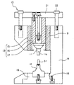
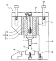
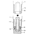
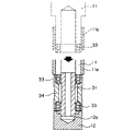
図1は作業前の本発明装置の概略断面図、図2は作業後の本発明装置の概略断面図、図3(a)はガイド手段の一部断面して示す平面図、(b)は縦断面図、図4は本装置を使用して組み立てた軸受ユニットの断面図、図5乃至図7は本装置を使用した軸受ユニットの組立装置の工程図で、図5は軸に一方の軸受を圧入する工程を示す図、図6は前記軸受の外径にハウジングを圧入する工程を示す図、図7は前記軸とハウジングの間に他方の軸受を圧入する工程を示す図である。 1 is a schematic cross-sectional view of the device of the present invention before work, FIG. 2 is a schematic cross-sectional view of the device of the present invention after work, FIG. 3A is a plan view showing a partial cross-section of the guide means, and FIG. FIG. 4 is a cross-sectional view of a bearing unit assembled using the present apparatus, FIGS. 5 to 7 are process diagrams of a bearing unit assembling apparatus using the present apparatus, and FIG. FIG. 6 is a diagram showing a process of press-fitting a housing into the outer diameter of the bearing, and FIG. 7 is a diagram showing a process of press-fitting the other bearing between the shaft and the housing.
これらの図面に示すように、本実施例にかかる装置10は、可動側部材11と固定側部材12を同心に取付位置決めする構造を有し、例えば、可動側部材としての可動型(上型)と固定側部材としての固定型(下型)からなる金型を開閉若しくは型締等する金型装置や、固定側部材としての軸(シャフト)に、可動側部材としての軸受やハウジング等を組込んでなる軸受ユニットを組み立てる装置などが代表的な使用例として挙げられる。
すなわち、本発明によれば、外フレームに対して固定して配置される部材(例えば、前記下型や、軸等)を固定側部材とし、前記外フレームに沿って移動可能に配置される部材(例えば、前記上型や、前記軸に組込まれる軸受やハウジング等)を可動側部材とし、該可動側部材がガイド手段によって固定側部材方向へと同心で移動し位置決めされて所望な作業(金型開閉作業や型締作業、若しくは軸受ユニットの組立て作業)が行ない得る。
As shown in these drawings, the
That is, according to the present invention, a member (for example, the lower mold or the shaft) that is fixedly disposed with respect to the outer frame is a fixed-side member, and the member is disposed so as to be movable along the outer frame. (For example, the upper mold, a bearing or a housing incorporated in the shaft, etc.) is used as a movable member, and the movable member is moved and positioned concentrically in the direction of the fixed member by the guide means to perform a desired work (gold Mold opening / closing operations, mold clamping operations, or bearing unit assembly operations).
図中、14は縦断側面視略コの字形状の外フレームを示し、該外フレーム14には、その下部に荷重中心の嵌合穴18を設けると共に、該嵌合穴18に下型ホルダ19と、該下型ホルダ19に取り付け固定される下型(固定側部材)12を備え、前記外フレーム14の上部には、前記下型12と対向する位置に設けた嵌合孔9に、該下型12と同心にて備えたガイド手段13と、該ガイド手段13に上下移動可能に取り付けた上型(可動側部材)11とを備えている。
In the figure,
前記ガイド手段13は、例えば図3に示すように、外フレーム14に接着固定される円筒状のブッシュ(固定部)15と、外フレーム14に沿って平行に摺動可能で、荷重中心と同心に前記ブッシュ15の内径に配置され、上型11を取付け可能な円筒状のポスト(摺動部)17と、該ポスト17の外周面と前記ブッシュ15の内周面で摺動変位する円筒状の案内部材16とにより構成されている。
For example, as shown in FIG. 3, the guide means 13 is slidable in parallel along the
前記ガイド手段13は、本実施例によれば、上型11の上端細筒部を、ポスト17の内径に同心で嵌合させると共にボルトを介して、ポスト17上面に固定した昇降部材21と一体的に取付け、該昇降部材21を図示しない機械プレスのラムまたはハンドプレスの加工軸と連結することで、昇降部材21とポスト17と上型11が一体的に上下方向に変位して、下型12と同心で接近・離反を行うようにしている。なお、図中22は昇降部材21の案内ガイドである。
According to the present embodiment, the guide means 13 is integrated with an
前記案内部材16は、軸方向に等間隔で穿設した多数個のポケット16aを有する円筒状の保持器(リテーナ)と、該夫々のポケット16a内に夫々一個ずつ転動自在に組込まれている多数個の転動体(円筒ころ)8を備えて構成されている。本実施例では、平面視薄肉部分に前記ポケット16aを軸方向に多数穿設している。
また、本実施例では、前記軸方向の転動体8群を周方向に等間隔若しくは略等間隔で6列備える構成を採用している。
The
Further, in this embodiment, a configuration is adopted in which the eight axial rolling elements are provided in six rows at equal intervals or substantially equal intervals in the circumferential direction.
前記ブッシュ15の内周面とポスト17の外周面には、軸方向に平坦な転動案内面15a,17aが、周方向に6列備えられており、夫々の平坦な転動案内面15a,17aに前記多数個のころ8が線接触で転動する。また、ころ8は、前記ブッシュ15の転動案内面15aとポスト17の転動案内面17aと負のすきまで予圧を掛けた状態で摺動するものとしている。
The inner circumferential surface of the
本実施例では、転動体8と、該転動体8が案内される転動案内面15a,17aを夫々周方向に等間隔若しくは略等間隔で6列備える構成としているが、これになんら限定されるものではなく、本発明の範囲内で設計変更可能である。
また、前記ブッシュ15、摺動部17および案内部材16は、一例を示したにすぎず、何等限定されず本発明の範囲内で変更可能である。
In this embodiment, the rolling
Further, the
このようなガイド手段13を金型装置の荷重中心に配設することにより、摺動全域で剛性が向上し、加工中に上型が芯ずれを起こすようなことがなくなる。
この結果、上下型の同軸度を高精度に保持でき、加工精度と金型の耐久性の向上に寄与することとなる。
尚、本実施例では可動側部材としての可動型に上型11を、固定側部材としての固定型に下型12をもって説明するが、上型を固定型としての固定側部材とし、下型を可動型としての可動側部材とすることも可能で本発明の範囲内である。
By disposing such guide means 13 at the center of the load of the mold apparatus, the rigidity is improved over the entire sliding area, and the upper mold does not cause misalignment during processing.
As a result, the coaxiality of the upper and lower molds can be maintained with high accuracy, which contributes to the improvement of the machining accuracy and the durability of the mold.
In this embodiment, the upper mold 11 is described as a movable mold as a movable side member and the
次に、本発明にかかる装置を用いて、軸受ユニット30を組み立てる軸受ユニット組立装置の一例を図に基づいて説明する。なお、本実施例では、前記可動側部材として説明した上型11や固定側部材として説明した下型12に代えて、前記下型12に立設させた軸31を固定側部材とし、上型11のホールド治具11aを介して前記軸31に組込まれる軸受33やハウジング34を可動側部材としている。
Next, an example of a bearing unit assembling apparatus for assembling the bearing
図1及び図2、図5乃至図7は、図4に示すような軸受ユニット30を圧入組み立てする工程の概略図である。
「第1工程」
図1及び図5は第1工程にかかる概略図であり、この第1工程は、軸31のフランジ32側外周面に軸受33を圧入する状態を示す。下型12の位置決め穴12a内へ一端側にフランジ32を有する軸31を挿入した後、上型11のホールド治具11aに軸受33を装着し、該上型11の下降により、軸31のフランジ32面まで前記軸受33を加圧圧入する。
1 and 2 and FIGS. 5 to 7 are schematic views of a process for press-fitting and assembling the bearing
"First step"
FIG. 1 and FIG. 5 are schematic views according to the first step. This first step shows a state in which the
「第2工程」
図6は第2工程にかかる概略図であり、この第2工程は、前記軸受33を軸31に圧入した後、その軸受33外径にハウジング34を圧入する状態を示す。すなわち、前記フランジ32に当接する位置まで軸受33を圧入した軸を、下型12の位置決め穴12aに挿入した後、上型11のホールド治具11aに装着したハウジング34を下降させることにより、ハウジング34内側面部が軸受33の外径と密着するまで加圧圧入する。
"Second step"
FIG. 6 is a schematic view according to the second step. This second step shows a state in which the
「第3工程」
図2及び図7は第3工程にかかる概略図であり、この第3工程は、前記軸受33の外径にハウジング34を圧入した部品の軸31の一端側近傍に、軸受33を圧入する状態を示す。下型12の位置決め穴12aに前記部品を挿入した後、上型11のホールド治具11aに装着した軸受33を上型11の下降によりハウジング34内周面と軸31外周面とに同時に加圧圧入する。
"Third step"
2 and 7 are schematic views according to the third step. In the third step, the
このように、前記三工程により、軸受ユニット30を組み立てるようにしているが、本発明にかかる位置決め装置を用いた軸受ユニット組立て装置により、軸受33、ハウジング34、軸31の圧入時にカジリ易いという問題が解消され、軸受ユニットの組み立て時における同心精度を保持できカジリが抑制されることとなる。なお、本実施例の軸受ユニット組立工程は一実施例にすぎずこれに限定解釈されるものではなく、本発明の範囲内で設計変更可能である。
As described above, the bearing
この結果、圧入時の作業性と圧入後の軸受ユニットの組み立て精度が向上し、組立体の予圧設定が適切に行われる。
さらに、金型装置の作業能率向上により、製造コストを削減することに寄与することとなる。
As a result, workability at the time of press-fitting and assembly accuracy of the bearing unit after press-fitting are improved, and preload setting of the assembly is appropriately performed.
Furthermore, the improvement of the working efficiency of the mold apparatus contributes to the reduction of the manufacturing cost.
8 転動体(ころ)
11 上型(可動側部材)
12 下型(固定側部材)
13 ガイド手段
14 外フレーム
15 ブッシュ
16 案内部材
17 ポスト
31 軸(固定側部材)
33 軸受(可動側部材)
34 ハウジング(可動側部材)
8 Rolling elements (rollers)
11 Upper mold (movable member)
12 Lower mold (fixed side member)
13 Guide means 14
33 Bearing (movable side member)
34 Housing (movable side member)
Claims (7)
前記可動側部材は、外フレームに嵌合固定されたガイド手段に同心で嵌合され、
前記ガイド手段は、外フレームに固定される固定部と、前記可動側部材を取付け配置すると共に、前記固定部との間に案内部材を介して外フレームに沿って移動可能に配設されている摺動部とからなり、
前記案内部材は、前記固定部と摺動部に備えた転動案内面と線接触する多数の転動体と、該転動体を組込む保持器とで構成されており、該転動体は前記転動案内面と負のすきまで接していることを特徴とする可動側部材と固定側部材の位置決め装置。 A device for positioning concentrically a movable side member arranged movably along an outer frame and a fixed side member arranged fixed to the outer frame,
The movable side member is concentrically fitted to guide means fitted and fixed to the outer frame,
The guide means has a fixed portion fixed to an outer frame and the movable side member attached thereto, and is disposed between the fixed portion so as to be movable along the outer frame via a guide member. Consisting of sliding parts,
The guide member includes a plurality of rolling elements that are in line contact with rolling guide surfaces provided in the fixed part and the sliding part, and a cage that incorporates the rolling elements. A positioning device for a movable side member and a fixed side member, wherein the positioning member is in contact with the guide surface up to a negative clearance.
4. A method for assembling a bearing unit, wherein the bearing, the housing, and the shaft are assembled together using the movable-side member and fixed-side member positioning device according to claim 1.
Priority Applications (1)
| Application Number | Priority Date | Filing Date | Title |
|---|---|---|---|
| JP2004106672A JP2005288620A (en) | 2004-03-31 | 2004-03-31 | Positioning device for movable side member and stationary side member and bearing unit assembling device using it |
Applications Claiming Priority (1)
| Application Number | Priority Date | Filing Date | Title |
|---|---|---|---|
| JP2004106672A JP2005288620A (en) | 2004-03-31 | 2004-03-31 | Positioning device for movable side member and stationary side member and bearing unit assembling device using it |
Publications (2)
| Publication Number | Publication Date |
|---|---|
| JP2005288620A true JP2005288620A (en) | 2005-10-20 |
| JP2005288620A5 JP2005288620A5 (en) | 2007-05-24 |
Family
ID=35322148
Family Applications (1)
| Application Number | Title | Priority Date | Filing Date |
|---|---|---|---|
| JP2004106672A Pending JP2005288620A (en) | 2004-03-31 | 2004-03-31 | Positioning device for movable side member and stationary side member and bearing unit assembling device using it |
Country Status (1)
| Country | Link |
|---|---|
| JP (1) | JP2005288620A (en) |
Cited By (5)
| Publication number | Priority date | Publication date | Assignee | Title |
|---|---|---|---|---|
| CN102303625A (en) * | 2011-06-17 | 2012-01-04 | 中国北车集团大连机车车辆有限公司 | Assembling device and disassembling device for split-type traction link of locomotive |
| CN104251266A (en) * | 2014-09-24 | 2014-12-31 | 西安泰富西玛电机有限公司 | Bearing assembly collision prevention device and bearing assembling method adopting device |
| CN105033614A (en) * | 2015-08-28 | 2015-11-11 | 芜湖科创生产力促进中心有限责任公司 | Special bearing press-mounting machine for right-angle gear reducer |
| CN105773518A (en) * | 2016-04-19 | 2016-07-20 | 江西江铃底盘股份有限公司 | Press-fitting system and method for main speed reducer shell and flange head |
| WO2022036809A1 (en) * | 2020-08-18 | 2022-02-24 | 惠州海卓科赛医疗有限公司 | Bearing assembling device |
-
2004
- 2004-03-31 JP JP2004106672A patent/JP2005288620A/en active Pending
Cited By (6)
| Publication number | Priority date | Publication date | Assignee | Title |
|---|---|---|---|---|
| CN102303625A (en) * | 2011-06-17 | 2012-01-04 | 中国北车集团大连机车车辆有限公司 | Assembling device and disassembling device for split-type traction link of locomotive |
| CN104251266A (en) * | 2014-09-24 | 2014-12-31 | 西安泰富西玛电机有限公司 | Bearing assembly collision prevention device and bearing assembling method adopting device |
| CN105033614A (en) * | 2015-08-28 | 2015-11-11 | 芜湖科创生产力促进中心有限责任公司 | Special bearing press-mounting machine for right-angle gear reducer |
| CN105773518A (en) * | 2016-04-19 | 2016-07-20 | 江西江铃底盘股份有限公司 | Press-fitting system and method for main speed reducer shell and flange head |
| CN105773518B (en) * | 2016-04-19 | 2017-10-03 | 江西江铃底盘股份有限公司 | A kind of press mounting system and its pressing method of final drive casing and collar head |
| WO2022036809A1 (en) * | 2020-08-18 | 2022-02-24 | 惠州海卓科赛医疗有限公司 | Bearing assembling device |
Similar Documents
| Publication | Publication Date | Title |
|---|---|---|
| CN102720769B (en) | Device for mounting sealing ring of rolling bearing in pressing mode and method for mounting sealing ring in pressing mode | |
| CA2494371C (en) | Ram guidance system | |
| CN109483121B (en) | Welding jig and welding frock | |
| EP1166925A2 (en) | Self-centering trim punch | |
| CN108698180A (en) | With the clamping device for lifting function | |
| JP2005288620A (en) | Positioning device for movable side member and stationary side member and bearing unit assembling device using it | |
| JP2002337000A (en) | Guide arrangement for machine tool | |
| JP2014104495A (en) | Shell body manufacturing device and shell body manufacturing method | |
| KR20080017231A (en) | Press machine with linear motor | |
| KR20130008961A (en) | The centering jig device which applied a bearing | |
| JP4782556B2 (en) | Clearance designation guide set | |
| JP2014100769A (en) | Bearing press-fitting device | |
| CN202690784U (en) | Pressing mold of rolling bearing sealing ring | |
| US10870229B2 (en) | Mold stack for injection molding machine | |
| JPH11319983A (en) | Punching press of cylindrical work having internally stepped groove | |
| CN109396248B (en) | Punching device | |
| CN212432522U (en) | Feeding and clamping device for bearing radial clearance measuring equipment | |
| US6122952A (en) | Multiple actuation press for metal working and method of metal forming | |
| JP2022110321A (en) | Snap ring assembling device | |
| US20040208952A1 (en) | Mold clamping mechanism of molding machine | |
| CN220006449U (en) | High-wear-resistance low-noise automobile bearing assembly device | |
| CN109210093B (en) | Locating and positioning device for plane thrust bearing | |
| US6237454B1 (en) | Self-centering trim punch | |
| JP2018202456A (en) | Forging apparatus | |
| CN220613153U (en) | Zero point positioning mechanism in CNC machine |
Legal Events
| Date | Code | Title | Description |
|---|---|---|---|
| A521 | Written amendment |
Free format text: JAPANESE INTERMEDIATE CODE: A523 Effective date: 20070328 |
|
| A621 | Written request for application examination |
Free format text: JAPANESE INTERMEDIATE CODE: A621 Effective date: 20070328 |
|
| A977 | Report on retrieval |
Free format text: JAPANESE INTERMEDIATE CODE: A971007 Effective date: 20080912 |
|
| A131 | Notification of reasons for refusal |
Free format text: JAPANESE INTERMEDIATE CODE: A131 Effective date: 20080930 |
|
| A02 | Decision of refusal |
Free format text: JAPANESE INTERMEDIATE CODE: A02 Effective date: 20090310 |