JP2005288385A - Water activation device - Google Patents
Water activation device Download PDFInfo
- Publication number
- JP2005288385A JP2005288385A JP2004110165A JP2004110165A JP2005288385A JP 2005288385 A JP2005288385 A JP 2005288385A JP 2004110165 A JP2004110165 A JP 2004110165A JP 2004110165 A JP2004110165 A JP 2004110165A JP 2005288385 A JP2005288385 A JP 2005288385A
- Authority
- JP
- Japan
- Prior art keywords
- water
- main body
- body container
- base material
- high voltage
- Prior art date
- Legal status (The legal status is an assumption and is not a legal conclusion. Google has not performed a legal analysis and makes no representation as to the accuracy of the status listed.)
- Pending
Links
- WRQOPPZJPSGEDO-UHFFFAOYSA-N C1C2OCCCC12 Chemical compound C1C2OCCCC12 WRQOPPZJPSGEDO-UHFFFAOYSA-N 0.000 description 1
Images


Abstract
Description
本発明は、水を活水化させる活水装置に関するものである。 The present invention relates to an active water device for activating water.
自然界においては、山間部に降った雨や積もった雪が地中に浸透して地下水となり、やがて湧き水となって川の源流を形成する。この過程において、鉱物や岩石からの遠赤外線やマイナスイオン作用や磁気作用により水分子の水素結合集団(クラスタ)が細分化されたり、岩への衝突や滝からの落下などで水分子同士の摩擦から生じた電子を受け取り還元性の水となる。このような状態にある水を活水というが、活水状態はそれほど長期間維持されず活水による種々の効果は徐々に失われていく。 In nature, rain and piled snow that falls in mountainous areas penetrates into the ground and becomes groundwater, and eventually springs and forms the source of the river. In this process, the water-bonded clusters (clusters) are subdivided by far-infrared rays, negative ion action and magnetic action from minerals and rocks, or friction between water molecules due to collision with rocks or falling from waterfalls. It receives the electrons generated from the water and becomes reducing water. Although water in such a state is called active water, the active water state is not maintained for a long period of time, and various effects of the active water are gradually lost.
そこで、従来からこの活水化作用の原理を応用して、内部空間にセラミック焼成粒を配置するなどして、これに通水させて攪拌すると共に水流の摩擦により、活水効果を失った水道水を再度活水化する活水装置が実用化されている。 Therefore, by applying the principle of this water activation action, ceramic fired grains are arranged in the internal space, and the tap water that has lost its active water effect due to water flow friction is stirred and passed through this. An active water apparatus for reactivating water has been put into practical use.
このような活水装置として、流入口と流出口とを有する導電性の筐体と、該筐体の外周側を絶縁材により覆い、かつ通水管と絶縁した導電性の被覆体と、鉱物を主成分として小塊状に成形した活水材と、から成り、該活水材を前記筐体の内部空間の流れ方向に沿って互いに触れることなくかつ多重に配置した活水装置が提案されている(例えば、下記の特許文献1参照。)。
しかしながら、上記のような活水装置では、活水材を筐体の内部空間の流れ方向に沿って互いに触れることなくかつ多重に配置しているが、その活水材が流入口からの流入水と衝突することにより振動して筐体の内面と擦れ合う可能性がある。すなわち、活水材が鉱物を主成分として成形されているため、筐体の内面がその活水材の振動を受けて徐々に磨耗していく。これにより、筐体を構成する物質が流入水に溶け込んで水質が変化したり、筐体自体が破損し水漏れの原因となる可能性がある。 However, in the active water device as described above, the active water materials are arranged in multiples without touching each other along the flow direction of the internal space of the housing, but the active water materials collide with the inflow water from the inflow port. There is a possibility of vibrating and rubbing against the inner surface of the housing. That is, since the active water material is formed mainly of minerals, the inner surface of the casing is gradually worn out by receiving vibration of the active water material. Thereby, the substance which comprises a housing | casing melt | dissolves in inflow water, water quality may change, or the housing | casing itself may be damaged and it may cause a water leak.
また、活水材が水流によって磨耗することにより、徐々に活水化させる能力が低下し、長期間の連続使用において安定した活水化を行なうことが困難である。これにより、定期的なメンテナンスを行なう必要があり、手間や労力がかかるとともに、ランニングコストが高くつくという問題がある。 In addition, when the active water material is worn by the water flow, the ability to gradually activate the water is lowered, and it is difficult to perform stable activation in continuous use for a long period of time. As a result, it is necessary to perform regular maintenance, which is troublesome and labor intensive and increases running costs.
本発明は、このような事情に鑑みなされたもので、水を効果的に活水化させる活水装置の提供を目的とする。 This invention is made | formed in view of such a situation, and it aims at provision of the active water apparatus which water-activates water effectively.
上記目的を達成するため、本発明の活水装置は、液体の流入口と流出口とを有する本体容器と、上記本体容器内に配置され、上記流入口から流入した液体を流出口へ導く過程で整流する整流部材とを備え、上記本体容器の内面は、遠赤外線を放射するセラミックス層により被覆され、上記整流部材は、当該整流部材の略中心部に配置されて上記流入口から流入する液体を中心付近で旋回させる内羽根と、上記内羽根の周辺部に形成されて上記流入口から流入する液体を外周付近で旋回させる外羽根と、上記外羽根の外周部において本体容器を通過する液体を上記セラミックス層に接触させる空間とを含んで構成されていることを要旨とする。 In order to achieve the above object, an active water device according to the present invention is a main body container having a liquid inlet and outlet, and is disposed in the main body container, in the process of guiding the liquid flowing in from the inlet to the outlet. A rectifying member that rectifies, the inner surface of the main body container is covered with a ceramic layer that emits far-infrared rays, and the rectifying member is disposed at a substantially central portion of the rectifying member and receives liquid flowing in from the inlet. An inner vane swirled near the center, an outer vane formed around the inner vane to swirl the liquid flowing in from the inlet near the outer periphery, and a liquid passing through the main body container at the outer peripheral portion of the outer vane. The gist of the invention is that it is configured to include a space in contact with the ceramic layer.
すなわち、本発明の活水装置によれば、流入口から流入した液体は、内羽根により中心付近で旋回するとともに、外羽根により外周付近で旋回しながら流出口へ導かれる。このとき、流入口から流入した液体に対して内羽根による整流と外羽根による整流により異なる流れが生じ、それらの異なる流れで互いに水分子同士の衝突や摩擦から電子を生じさせて水分子の水素結合集団(クラスタ)を細分化することができる。また、流入した液体を整流することができるため、流出口から流出する液体の量、流速、質等の液体の状態を安定させることができる。 That is, according to the active water device of the present invention, the liquid flowing in from the inflow port is swirled around the center by the inner blade and guided to the outflow port while swirling near the outer periphery by the outer blade. At this time, different flows are generated by the rectification by the inner blade and the rectification by the outer blade for the liquid flowing in from the inlet, and these different flows generate electrons from the collision and friction of water molecules with each other to generate hydrogen of water molecules. The combined population (cluster) can be subdivided. In addition, since the inflowing liquid can be rectified, the liquid state such as the amount, flow rate, and quality of the liquid flowing out from the outlet can be stabilized.
また、上記整流部材の空間により流入口から流入した液体を上記本体容器のセラミックス層に接触させることができるため、遠赤外線を直に放射することができ、液体の水分子を有効に振動させ液体に対する効果的な細分化が可能となる。また、セラミックス層により遠赤外線を放射するようにしているため、遠赤外線の放射能力が高く効果的な細分化が可能となるとともに、その放射能力やその持続力の低下が防止される。さらに、本体容器の内面は、セラミックス層により被覆されているため、引っかき強度等に優れ損傷しにくいうえ、酸やアルカリに侵されにくく、整流部材の接触や長期間の使用等に対する耐久性に優れる。 Further, since the liquid flowing in from the inlet can be brought into contact with the ceramic layer of the main body container by the space of the rectifying member, the far infrared rays can be directly emitted, and the liquid molecules of the liquid can be effectively vibrated to vibrate. Effective subdivision can be achieved. Further, since the ceramic layer emits far infrared rays, the far infrared rays have high radiation ability and effective subdivision is possible, and the radiation ability and its sustainability are prevented from being lowered. Furthermore, since the inner surface of the main body container is coated with a ceramic layer, it is excellent in scratch strength and is not easily damaged, and is not easily damaged by acid or alkali, and is excellent in durability against contact with a rectifying member or long-term use. .
このような構成により、メンテナンスを行なう手間が少なくなるとともに、ランニングコストが低く、細分化によって活水化された液体を長期間の連続使用においても安定して流出させることができる。 With such a configuration, the labor for maintenance is reduced, the running cost is low, and the liquid activated by subdivision can be stably discharged even in continuous use for a long period of time.
本発明の活水装置において、上記本体容器の母材は導電性材料から形成され、上記母材がアースされた場合には、上記本体容器に電気が蓄積されることを防止することができる。例えば、本体容器内を通過する液体の流れにより本体容器に静電気が発生したとき、その静電気が本体容器に蓄積されることを防止することができる。また、本体容器の静電気がアースにより誘導される際、セラミックス層から放射される遠赤外線により、本体容器内の液体に対して酸化還元電位を低下させるとともに、細分化することができる。 In the active water device of the present invention, the base material of the main body container is formed of a conductive material, and when the base material is grounded, it is possible to prevent electricity from being accumulated in the main body container. For example, when static electricity is generated in the main body container due to the flow of liquid passing through the main body container, the static electricity can be prevented from accumulating in the main body container. Further, when the static electricity of the main body container is induced by the ground, the far-infrared radiation radiated from the ceramic layer can lower the oxidation-reduction potential with respect to the liquid in the main body container and further subdivide it.
本発明の活水装置において、上記本体容器の母材は導電性から形成されるとともに、上記セラミックス層は絶縁性材料から形成され、上記本体容器の母材に対して高電圧を印加する高電圧印加手段を備えている場合には、高電圧印加手段による高電圧の印加により本体容器内の液体を本体容器方向へ静電誘導させることができる。例えば、プラスの電位で高電圧を印加することにより、本体容器の母材に対してセラミックス層を介して存在している液体が静電誘導され、結果的にマイナスに帯電し、液体の酸化還元電位は常に還元電位側に低く保たれるため、液体の酸化還元電位を低下させることができる。 In the active water apparatus according to the present invention, the base material of the main body container is formed of a conductive material, and the ceramic layer is formed of an insulating material, and applies a high voltage to the base material of the main body container. When the means is provided, the liquid in the main body container can be electrostatically induced toward the main body container by applying a high voltage by the high voltage applying means. For example, when a high voltage is applied at a positive potential, the liquid existing through the ceramic layer is electrostatically induced to the base material of the main body container, and as a result, the liquid is negatively charged. Since the potential is always kept low on the reduction potential side, the oxidation-reduction potential of the liquid can be lowered.
本発明の活水装置において、上記本体容器内の液体流出状態か止水状態かを判別する判別手段を備え、上記高電圧印加手段は、上記判別手段が流出状態と判別したとき本体容器の母材に対して高電圧を印加し、上記判別手段が止水状態と判別したとき本体容器の母材に対する高電圧の印加を解除する場合には、液体の流出時には高電圧の印加が解除され電圧の消費を抑え、液体の止水時には本体容器内の液体が劣化することを防止することができる。このように、本体容器の母材に対して高電圧を必要に応じて印加することで、効率よく活水化することができる。例えば、液体が飲料水や水道水である場合には本体容器内に雑菌が繁殖することを防止でき、衛生的である。 In the water activation apparatus of the present invention, it is provided with a discriminating unit for discriminating whether the liquid in the main body container is in a liquid outflow state or a water stoppage state, and the high voltage applying unit is When a high voltage is applied to the main body container when the high voltage is applied to the base material of the main body container when the determination means determines that the water is stopped, the application of the high voltage is canceled when the liquid flows out. Consumption can be suppressed, and deterioration of the liquid in the main body container can be prevented when the liquid is stopped. Thus, it can be activated efficiently by applying a high voltage to the base material of the main body container as necessary. For example, when the liquid is drinking water or tap water, it is possible to prevent germs from growing in the main body container, which is hygienic.
本発明の活水装置において、上記本体容器の母材に対して高電圧印加手段により高電圧を印加するか、上記本体容器の母材をアースするかを切り替える切替手段を備え、上記切替手段は、上記判別手段が止水状態と判別したとき本体容器の母材に対して高電圧印加手段により高電圧を印加し、上記判別手段が流水状態と判別したとき本体容器の母材をアースするよう切り替える場合には、本体容器内で停滞する液体の劣化防止と、本体容器内を通過する液体の流れによる本体容器に対する静電気の蓄積防止等を効率よく実現することができる。 In the active water device of the present invention, comprising a switching means for switching whether to apply a high voltage to the base material of the main body container by a high voltage application means, or to ground the base material of the main body container, the switching means, When the determining means determines that the water is stopped, a high voltage is applied to the base material of the main body container by the high voltage applying means, and when the determining means determines that the water is flowing, the base material of the main body container is switched to ground. In this case, it is possible to efficiently realize prevention of deterioration of the liquid stagnating in the main body container and prevention of accumulation of static electricity on the main body container due to the flow of liquid passing through the main body container.
つぎに、本発明を実施するための最良の形態を説明する。以下の説明は、活水装置を一般の上水道管に取付けて、上水道管を流れる水に対する活水化を実現した例を示す。 Next, the best mode for carrying out the present invention will be described. The following description shows an example in which an active water device is attached to a general water supply pipe and the water flowing through the water supply pipe is activated.
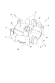
図1は、本発明の第1の実施例の活水装置を示す斜視図であり、活水装置を一部切断して示している。 FIG. 1 is a perspective view showing a water activation apparatus according to a first embodiment of the present invention, in which the water activation apparatus is partially cut away.
上記活水装置1は、水の流入口3aと流出口3bとを有する本体容器5と、本体容器5内に配置され、流入口3aから流入した水を流出口3bへ導く過程で整流する整流部材7とを備えている。
The
上記本体容器5は円筒状で、その一端部に流入口3aが、他端部に流出口3bが設けられている。流入口3aと流出口3bは、本体容器(筒)5の軸心部に設けられている。
The
なお、本体容器5は円筒状のほか、六角形や八角形等の正多角形とすることもできる。
The
上記整流部材7は、盤状で円筒状の本体容器5内に多数積層されている。詳細には、上記整流部材7は、盤状の整流部材7は筒の軸心すなわち水の流れる方向と直交するように配置されて積層されている。
A large number of the rectifying
本体容器5の両端には、その開口に被さるようにして水道管等の通水管に直列連結するための連結管6a,6bを水密状態で螺合接続させている。
上記流入口3aは連結管(流入側異径ソケット)6aの開放端となり、流出口3bは、連結管(流出側異径ソケット)6bの開放端となる。この連結管6a,6bの開放端の内周面には、通水管と水密に螺合連結するための内ネジ8を刻設している。
The
図2に示すように、上記本体容器5の母材9はアルミニウムからなり、本体容器5の内面は遠赤外線を放射するセラミックス層11により被覆されている。
As shown in FIG. 2, the
上記セラミックス層11を構成する材質としては、赤外領域の電磁波に対する放射率が70%以上の高放射率の値をとるものが好ましく、各種の材質のものを用いることができる。例えば、耐食性や絶縁性,引っかき強度等に優れた、アルミナを主成分とするセラミックス傾斜材が好適に用いられる。このアルミナを主成分とするセラミックス傾斜材は、本実施例のように、本体容器5の母材がアルミニウムである場合には、本体容器5の母材は、引っかき強度等や耐剥離性に優れ損傷しにくいうえ、水質が変化しにくい。
The material constituting the
上記セラミックス層11が、赤外領域の電磁波に対する放射率が70%以上の高放射率体である場合には、活性効果がより高くなる。すなわち、水には、3μm,6μm,9μm,12μm…という波長域に電磁波の吸収スペクトルが存在する。このうち、2.66μm,2.73μm,6.27μmの波長域は、電磁波の吸収により水分子を有効に振動させる。この振動により、水分子は細分化され、水を活水化することができるのである。
When the
上記セラミックス層11の皮膜の厚みとしては、5μm以上250μm以下が好適である。上記厚みの上限値としてさらに好ましいのは200μmであり、上記厚みの下限値としてさらに好ましいのは10μmである。セラミックス層11の厚みが5μm未満では、引っかき強度や耐食性の面で十分なものにならず、250μmを超えると、コスト的に好ましくないからである。
The thickness of the
つぎに、図3および図4を参照して、整流部材7ついて詳しく説明する。
Next, the rectifying
図3および図4(A)に示すように、上記整流部材7は、その整流部材7の略中心部に配置されて流入口3aから流入する水を中心付近で旋回させる内羽根21と、その内羽根21の周辺部に形成されて流入口3aから流入する水を外周付近で旋回させる外羽根23と、その外羽根23の外周部において本体容器を通過する水をセラミックス層11に接触させる空間25とを含んで構成されている。
As shown in FIG. 3 and FIG. 4 (A), the rectifying
上記内羽根21は、本体容器5の軸心部に配置され、その周辺部に外羽根が設けられている。上記内羽根21および外羽根23は、それぞれ2つづつ設けられ、本体容器5の軸心を中心とした旋回流を生じるように形成されている。内羽根21が生じる旋回流と、外羽根23が生じる旋回流は同じ方向(本実施例では右方向)になるように設定されている。これにより、水が通過するときに、2つの同心状の旋回流と遠赤外線放射により、水分子のクラスタが崩壊して活水効果が高くなる。なお、上記内羽根21および外羽根23の数は任意の数に設定してもよい。
The
上記外羽根23の軸心に対する角度は、内羽根21の軸心に対する角度よりも大きく設定されている。したがって、内羽根21による旋回流の前進スピードの方が、外羽根23による旋回流の前進スピードよりも大きくなる。これにより、2つの速度が異なる同心状の旋回流と遠赤外線放射により、水分子のクラスタがより崩壊して活水効果が高くなる。
The angle with respect to the axial center of the
上述のように、上記整流部材7が円筒状の本体容器5内に多数積層されていることで、本体容器5内に流入した液流は、ぐるぐると旋回しながら流出口3bへ導かれる。したがって、本体容器5から流入した水の流路は、本体容器5の流入口3aから流出口3bまでの本体容器5自体の長さよりも実質的に長くなる。すなわち、本体容器5から流入した水が整流部材7と接触する距離が長くなり、水のクラスタをより崩壊させることができるため、水の活水化を効率的に促進することができるとともに、活水装置1の小型化が実現される。
As described above, since a large number of the rectifying
上記内羽根21および外羽根23の大きさの比は、概ね1:3で設定されている。すなわち、整流部材7は、大きさの異なる羽根を有する。このように、整流部材7の略中心部に形成された内羽根21を外羽根23より小さくすることで、流入する水の量が少ない場合であっても、流入口3aから流入する水が略中心部に位置する内羽根21からこぼれ、外羽根23によっても整流される。したがって、内羽根21と外羽根23との両方の羽根で当該水を細分化することができる。これにより、流入する水の量が少なくても上記のような活水効果を発揮することができる。
The ratio of the sizes of the
上記外羽根23の外周部には、整流部材7を本体容器5内に位置決めする複数の位置決め部材27が形成されている。位置決め部材27は、内羽根21を筒の軸心部に位置決めするとともに、整流部材7自体を本体容器5内で容易に動かないように安定させる。これにより、水の整流を安定して行なうことができる。
A plurality of
上記整流部材7には、育成光線を放射する物質、放射性物質を含む鉱石、放射線を放射する希土類元素を含む天然鉱石が含まれていてもよい。このようにすることにより、本体容器5内の水に対して育成光線を放射する物質が育成光線を放射するとともに、放射性物質を含む鉱石からマイナスイオンが発生する。したがって、成長促進、血行促進、新陳代謝の促進、腰痛・肩凝り・冷え症・リウマチ・神経痛・生理痛の改善等の育成光線の効果が期待でき、疲労回復、リラクゼーション、血行促進、頭痛・不眠症・便秘の改善等のマイナスイオンの効果も期待できる。
The rectifying
「育成光線を放射する物質」としては、例えば、麦飯石、トルマリン、貝化石、天降石や黒鉛等を挙げることができる。しかし、これに限定するものではない。 Examples of the “substance that emits growing light” include barley stone, tourmaline, shell fossil, natural stone, graphite, and the like. However, the present invention is not limited to this.
また、「放射性物質を含む鉱石」や「放射線を放射する希土類元素を含む天然鉱石」としては、例えば、サマルスキー石、褐れん石、山口石(いわゆるジルコンを含む鉱石)、ピッチブレンド石(閃ウラン鉱)、ユークセン石、ペグマタイト石、モナズ石、ゼノタイム、コロンブ石、タンタル石、ガドリン石、バストネス石等を挙げることができる。しかし、これに限定するものではない。また、含まれる放射性物質としては、例えば、ウラン系列、アクチニウム系列、トリウム系列に分類されるものを挙げることができる。 Examples of “ores containing radioactive materials” and “natural ores containing rare earth elements that radiate radiation” include, for example, Samarsky stone, brown liquor, Yamaguchi stone (ores containing so-called zircon), pitch blend stones (flash uranium). Ore), eucsenite, pegmatite, monazite, xenotime, columbite, tantalum stone, gadolinite, bustness stone, and the like. However, the present invention is not limited to this. Moreover, as a radioactive substance contained, what is classified into a uranium series, an actinium series, and a thorium series can be mentioned, for example.
また、上記整流部材7にナイロン66材が含まれることで、自然界の力を用いて育成光線領域の安定化を促進することができる。
Further, since the rectifying
図4(B)に示すように、整流部材7は、整流部材7を同じ方向にそろえて積層するための嵌合部(凸部31および凹部33)を有する。具体的には、複数の位置決め部材27の上面(整流部材7の表面)には、それぞれ凹部33と嵌め合わすための凸部31が設けられている。その裏面には、それぞれ凸部31と嵌め合わすための凹部33が設けられている。したがって、複数の整流部材7を同じ方向にそろえて合体させ積層することができる。これにより、本体容器5内において、2つの速度が異なる同心状の旋廻流を全長にわたって均一に生じさせ、安定した活水効果を得ることができる。
As shown in FIG. 4B, the rectifying
また、本実施例では、位置決め部材27同士の間が水をセラミックス層11に接触させる空間25になっているため、整流部材7を同じ方向にそろえて積層することで、水をセラミックス層11に接触させる空間25により、流入口3aから流出口3bまで水の流路が直通する。これにより、流入する水による本体容器5内における圧力負荷を軽減することができる。
Further, in this embodiment, since the space between the positioning
このように、活水装置1によれば、流入口3aから流入した水は、内羽根21により中心付近で旋回するとともに、外羽根23により外周付近で旋回しながら流出口3bへ導かれる。このとき、流入口3aから流入した水に対して内羽根21による整流と外羽根23による整流により異なる流れが生じ、それらの異なる流れで互いに水分子同士の衝突や摩擦から電子を生じさせてクラスタを細分化することができる。また、流入した水を整流することができるため、流出口3aから流出する水の量、流速、質等の水の状態を安定させることができる。
As described above, according to the
また、上記整流部材7の空間により流入口3aから流入した水を本体容器5のセラミックス層11に接触させることができるため、遠赤外線を直に放射することができ、水の水分子を有効に振動させ水に対する効果的な細分化が可能となる。また、セラミックス層11により遠赤外線を放射するようにしているため、遠赤外線の放射能力が高く効果的な細分化が可能となるとともに、その放射能力やその持続力の低下が防止される。さらに、本体容器5の内面は、セラミックス層11により被覆されているため、引っかき強度等に優れ損傷しにくいうえ、酸やアルカリに侵されにくく、整流部材7の接触や長期間の使用等に対する耐久性に優れる。
Further, since the water flowing in from the
これにより、メンテナンスを行なう手間が少なくなるとともに、ランニングコストが低く、細分化によって活水化された水を長期間の連続使用においても安定して流出させることができる。 Thereby, the maintenance labor is reduced, the running cost is low, and the water activated by subdivision can be stably discharged even in continuous use for a long period of time.
また、一般の上水道には、塩素系の消毒・殺菌剤が混入されているが、これは菌に対して有効であっても、飲料水の味を悪化させている主源でもある。しかし、活水装置1では、塩素(Cl2)を2Cl−にし、塩酸(HCl)をH+とCl−にし、次亜塩素酸(HClO)をCl−とOH−にする。これにより、飲料水の味の悪化が改善され、味がまろやかになる。
Moreover, although the chlorine-based disinfection and disinfectant is mixed in the general water supply, this is the main source which is effective with respect to a microbe and deteriorating the taste of drinking water. However, in the
また、活水装置1を水道管(上水道や下水道)や水を用いる装置等に用いることで、これらを洗浄する手間や労力が省けるとともに、河川の汚濁防止につながり、水の循環サイクルの健全化に貢献される。
In addition, by using the
また、一般家庭に用いられる上水道の水を活水化することで、台所や洗濯の際等で消費される洗剤の使用量を減らすことができる。これにより、河川の汚濁防止につながり、水の循環サイクルの健全化に貢献される。 Moreover, the amount of detergent consumed in the kitchen or laundry can be reduced by rejuvenating the water from the water supply used in general households. This leads to prevention of river pollution and contributes to the soundness of the water circulation cycle.
なお、本実施例では、液体として上水道の水を活水化するため、その水が飲料水や入浴等に用いられるが、上水道の水でなくても、下水道や水冷式の冷却装置等にも好適に用いることができる。この場合、例えば、整流部材7の外羽根23に外羽根23を貫通する孔35を形成し、その孔35に銅板を差し込んで本体容器5内に銅板を配置してもよい。このようにすることで、銅には殺菌作用があるため、上述の効果に加えて雑菌や藻の繁殖を強力に抑えることができ、水道管や水を用いる装置等を洗浄する手間や労力が省けるとともに、河川の汚濁防止につながり、水の循環サイクルの健全化に貢献される。
In this embodiment, the water of the water supply is activated as a liquid, so that the water is used for drinking water, bathing, etc., but it is suitable not only for water supply but also for a sewer or a water-cooled cooling device. Can be used. In this case, for example, a
[実験例1] [Experiment 1]
つぎに、図5を参照して、実験例1について説明する。 Next, Experimental Example 1 will be described with reference to FIG.
実験例1では、活水装置1の電圧特性を確認するために実験を行なった。
In Experimental Example 1, an experiment was performed to confirm the voltage characteristics of the
(測定方法1) (Measurement method 1)
水道栓には、シャワーと蛇口との切替栓が設けられており、通常水(原水)と活水装置1を通過した通過水とを容易に切り替えて採取できるように、シャワーのヘッド部を取り外し、シャワーのホースを活水装置1の流入口に接続し、活水装置1を水平に設置した。
The faucet is equipped with a shower and faucet selector tap, and the shower head is removed so that normal water (raw water) and the passing water that has passed through the
図5(A)に示すように、活水装置1内に原水を流入させ、連結管(流入側異径ソケット)6aの位置A、本体容器5の外面中央部の位置B、連結管(流出側異径ソケット)6bの位置Cでそれぞれ活水装置1の本体容器5に生じる動作電圧(ボルト)を測定した。このとき、活水装置1の本体容器5の外面中央部を導線によりアースした場合とアースしていない場合においても動作電圧を測定した。
As shown in FIG. 5 (A), raw water is allowed to flow into the
(実験結果1) (Experimental result 1)
図5(B)を参照して、従来の活水装置と、アースしていない活水装置(アース無しの活水装置)1と、アースした活水装置(アース有りの活水装置)1とを比較して実験結果を説明する。 Referring to FIG. 5 (B), an experiment was conducted comparing a conventional live water device, a non-grounded live water device (a grounded water device) 1 and a grounded live water device (a grounded water device) 1. The results will be explained.
従来の活水装置では、位置A、位置B,位置Cでの動作電圧は、それぞれ0.04Vで安定していた。アース無しの活水装置1では、位置Aでの動作電圧は0.026〜0.053V、位置Bでの動作電圧は−0.243〜−0.189V、位置Cでの動作電圧は0.074〜0.106Vであった。アース有りの活水装置1では、位置Aでの動作電圧は0.178V、位置Bでの動作電圧は−0.315V、位置Cでの動作電圧は0.196でそれぞれ安定していた。
In the conventional water activation apparatus, the operating voltages at position A, position B, and position C were each stable at 0.04V. In the
この結果、従来の活水装置では、異径ソケットと本体容器とが絶縁されていないことと、活水装置をアースした方が動作電圧が安定することがわかった。 As a result, it was found that in the conventional live water device, the different diameter socket and the main body container are not insulated, and that the operating voltage is more stable when the live water device is grounded.
なお、図示していないが、従来の活水装置の抵抗値は3.2メガオーム(MO)であるのに対して、活水装置1の抵抗値は9.25メガオーム(MO)であった。
Although not shown, the resistance value of the conventional water activation apparatus is 3.2 megaohms (MO), whereas the resistance value of the
このことから、活水装置1は、両端がプラス(+)の特性を持ち、中央部がマイナス(−)の特性を持つことが明らかになった。一般的に、ステンレス管では、管全体がプラスの特性を持ち、活水装置1のように中央部がマイナスの特性を持つことがない。
From this, it became clear that the
[実験例2] [Experiment 2]
図6および図7を参照して、実験例2について説明する。 Experimental example 2 will be described with reference to FIGS. 6 and 7.
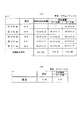
実験例2では、原水、従来の活水装置および活水装置1の通過水の酸化還元電位(ORP:Oxidation Reduction Potential)と、水素イオン濃度(pH)、塩素イオン濃度(Cl−濃度)とをそれぞれ確認する実験を行なった。
In Experimental Example 2, the oxidation-reduction potential (ORP), the hydrogen ion concentration (pH), and the chlorine ion concentration (Cl − concentration) of the raw water, the conventional active water device, and the passing water of the
(測定方法) (Measuring method)
従来の活水装置、アース無しの活水装置1、アース有りの活水装置1からの通過水を採取し、それぞれを比較する。
The passing water from the conventional live water device, the
(実験結果) (Experimental result)
従来の活水装置、アース無しの活水装置1、アース有りの活水装置1の通過水を比較した実験結果を説明する。図示の()内の数値は原水に対しての増減比である。
The experimental results of comparing the passing water of the conventional active water device, the
図6(A)に示すように、酸化還元電位(ORP)においては、増減比の平均を見ると、従来の活水装置、アース無しの活水装置1、アース有りの活水装置1の順に、酸化還元電位を低下させる力が強いことがわかった。また、従来の活水装置では、原水に対して酸化還元電位がプラスになっている場合があるが、活水装置1では、水を通過させると酸化還元電位が低下の方向へ向かうことがわかった。
As shown in FIG. 6 (A), in the oxidation-reduction potential (ORP), when the average of the increase / decrease ratio is seen, the oxidation / reduction is performed in the order of the conventional active water device, the
図6(B)に示すように、水素イオン濃度(pH)においては、増減比の平均を見ると、従来の活水装置、アース無しの活水装置1、アース有りの活水装置1の順に、水酸イオン濃度が高くなっていることがわかった。すなわち、活水装置1の方が原水をアルカリ性にする効果が強い。また、アース無しの活水装置1よりアース有りの活水装置1の方が原水をアルカリ性にする効果が強いこともわかった。
As shown in FIG. 6 (B), in the hydrogen ion concentration (pH), when the average of the increase / decrease ratio is seen, the conventional active water device, the
図7(A)に示すように、塩素イオン濃度(Cl−濃度)においては、増減比の平均を見ると、従来の活水装置、アース無しの活水装置1、アース有りの活水装置1の順に、塩素イオン濃度が高くなっていることがわかった。
As shown in FIG. 7A, in the chloride ion concentration (Cl − concentration), when the average of the increase / decrease ratio is seen, the conventional active water device, the
以上の実験結果から従来の活水装置より活水効果が高いことが確認できた。また、原水と従来の活水装置の通過水の平均水温が15.375℃であったのに対して、活水装置1の通過水の平均水温は16.53℃と1.155℃高く遠赤外線による効果を顕著に受けたことが確認できた。
[実験例3]
From the above experimental results, it was confirmed that the water activation effect was higher than that of the conventional water activation apparatus. Moreover, while the average water temperature of raw water and the passing water of the conventional active water apparatus was 15.375 degreeC, the average water temperature of the passing water of the
[Experiment 3]
つぎに、図7(B)を参照して、実験例3について説明する。 Next, Experimental Example 3 will be described with reference to FIG.
実験例3では、活水装置1による水のクラスタ化を確認する実験を行なった。
In Experimental Example 3, an experiment for confirming the clustering of water by the
(実験方法) (experimental method)
1:原水を検査コップの中から20cc採水し、別の検査コップを逆さまにして底の部分に静かに落とす。
2:アース有りの活水装置1を通過した後の通過水を検査コップに採水し上記と同じようにする。
3:上記の両者の水を並べて水平の台の上に載せる。
4:水平位置から目視し、ノギスで高さを計った。
1: Take 20 cc of raw water from the inspection cup, and place another inspection cup upside down and gently drop it on the bottom.
2: The passing water after passing through the grounded
3: Place both of the above water side by side on a horizontal table.
4: Visually observed from a horizontal position and measured with a caliper.
(実験結果) (Experimental result)
図7(B)に示すように、原水の高さは、5.10mmであり、活水装置1の通過水は4.97mmであった。以上の実験結果から活水装置1の通過水が細分化されていることがわかった。
As shown in FIG. 7B, the height of the raw water was 5.10 mm, and the passing water of the
すなわち、本体容器5の母材9は導電性材料から形成され、母材9がアースされた場合には、本体容器5に電気が蓄積されることを防止することができる。例えば、本体容器5内を通過する水の流れにより本体容器5に静電気が発生したとき、その静電気が本体容器5に蓄積されることを防止することができる。また、本体容器5の静電気がアースにより誘導される際、セラミックス層11から放射される遠赤外線により、本体容器5内の水に対して酸化還元電位を低下させるとともに、細分化することができる。
That is, the
なお、活水装置1を地中に埋めてアース(接地)接続を行なうようにしてもよい。
[実験例4]
In addition, you may make it earth | ground (grounding) connection by burying the
[Experiment 4]
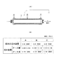
つぎに、図8を参照して、実験例4について説明する。 Next, experimental example 4 will be described with reference to FIG.
実験例4では、本体容器5内に、円筒状の導電性を有する補助体を配置して活水装置1の通過水の塩素濃度を確認する実験を行なった。
In Experimental Example 4, an experiment was performed in which a cylindrical conductive auxiliary body was placed in the
(実験方法) (experimental method)
1:まず、オルトトリジン試薬反応試験の基準となる「原水」を採取する。このとき、水道管内で塩素濃度が低くなっている停滞水が基準にならないように、水栓を1/3〜1/2開放し、30秒〜1分位放流後、検査コップに約100cc採取した。
2:つぎに、水道蛇口にホースをつなぎ、活水装置1に接続する。
3:図8(A)に示すように、本体容器5の外面の配線接点部分に、高電圧発生器のプラス極側の導線を接触固定し、マイナス極側の導線を本体容器5内の補助体に接触固定し、活水装置1を水平に配置した。
4:高電圧発生器の電源を入れ、水栓を最大開放し(この場合、毎分20リットル)、活水装置1の通常採水(活水装置1の略軸心部を通過する通過水)を検査コップに約100cc採水する。通電すると、電界は生じ、0.1ミリガウスから0.2ミリガウスに上昇した。
5:ついで、水栓を1/2開放と1/3にし(この場合、毎分6リットル)、同じように通常採水を採水する。
6:つぎに、水栓を最大開放し、本体容器5と補助体の間をぬって出てくる間接水採水(活水装置1内の本体容器5と補助体の間を通過する通過水)を検査コップに約100cc採水する。
7:今度は、水栓を1/2開放と1/3開放にしてそれぞれ検査コップに同じように本体容器5と補助体の間をぬって出てくる間接水採水を採水する。
8:オルトトリジン液を検査コップに2〜3滴垂らし、手に持って3回ほど検査コップを右方向に回転させ撹拌する。各検査コップは、同じ条件にて行ない、反応を見る。
1: First, “raw water” which is a standard for the orthotolidine reagent reaction test is collected. At this time, so that stagnant water with low chlorine concentration in the water pipe does not become a standard, open the
2: Next, a hose is connected to the tap and connected to the
3: As shown in FIG. 8 (A), the positive electrode side lead wire of the high voltage generator is contacted and fixed to the wiring contact portion on the outer surface of the
4: Turn on the high-voltage generator, open the faucet to the maximum (in this case, 20 liters per minute), and collect normal water from the active water device 1 (passing water passing through the approximate axial center of the active water device 1). About 100 cc of water is collected in the inspection cup. When energized, an electric field was generated and increased from 0.1 milligauss to 0.2 milligauss.
5: Next, the faucet is set to 1/2 open and 1/3 (in this case, 6 liters per minute), and normal water is collected in the same manner.
6: Next, the faucet is opened to the maximum, and indirect water sampling comes out between the
7: This time, the faucet is opened 1/2 and 1/3 opened, and the indirect water sample coming out between the
8: Drop 2 to 3 drops of orthotolidine solution on the inspection cup, hold it in your hand and rotate the inspection cup clockwise about 3 times and stir. Each test cup is run under the same conditions and sees the reaction.
(実験結果) (Experimental result)
図8(B)に示すように、原水の塩素濃度は、1.5ppmである。それに対して、通常採水において、水栓を最大開放した場合(全開)には1.5ppm、1/2開放した場合にも1.5ppm、1/3開放した場合には1.0ppmであった。一方、間接水採水において、水栓を最大開放した場合(全開)には1.5ppm、1/2開放した場合には1.0ppm、1/3開放した場合には0.8ppmであった。このことから、間接水採水の方が塩素濃度が低いことがわかった。また、本体容器5の外面全体の極性をプラスにして、本体容器5の内面にセラミックス層11を介してマイナス極性を持つ物質を誘導し、誘導される物質の電子軌道に遊離電子を与え、水を中和することができることがわかった。
As shown in FIG. 8B, the chlorine concentration of the raw water is 1.5 ppm. On the other hand, in normal sampling, 1.5 ppm when the faucet is fully opened (fully open), 1.5 ppm when 1/2 is opened, and 1.0 ppm when 1/3 is opened. It was. On the other hand, in indirect water sampling, it was 1.5 ppm when the faucet was fully opened (fully opened), 1.0 ppm when 1/2 opened, and 0.8 ppm when opened 1/3 . From this, it was found that indirect water sampling had a lower chlorine concentration. Further, the polarity of the entire outer surface of the
すなわち、本体容器5の母材9は導電性から形成されるとともに、セラミックス層11は絶縁性材料から形成され、本体容器5の母材9に対して高電圧を印加する高電圧印加手段としての高電圧発生器を備えている場合には、高電圧発生器による高電圧の印加により本体容器内の液体を本体容器方向へ静電誘導させることができる。
That is, the
図9に示すように、本体容器5内に、セラミックス層11を介して水が存在している。母材9に、プラスの電圧が印加されることにより、母材9はプラスの電位を保ち、母材9に対してセラミックス層11を介して存在する水は、静電誘導されてマイナスに帯電する。
As shown in FIG. 9, water is present in the
このように、内部の水が、マイナスの電位に保持されることにより、酸化還元電位が還元側に維持され、水が電子を奪われて酸化するのを防止でき、水の酸化還元電位を低下させることができる。 In this way, the internal water is held at a negative potential, so that the redox potential is maintained on the reduction side, and water can be prevented from being deprived and oxidized, thereby reducing the redox potential of water. Can be made.
このとき、上記母材9に印可する電圧としては、概ね0V以上3kV以下が好ましい。すなわち、水の電位を−3kV以上0V以下に維持するのが好ましい。印可する電圧が0V未満では、水の静電誘導による酸化防止効果に欠しく、3kVを超えるものにするには、装置が大掛かりとなり、コストアップとなって現実的でないからである。
At this time, the voltage applied to the
さらに、本体容器5は、その内面に、高放射率のセラミックス層11が形成されているため、水の酸化を防止でき、飲料水としての味の変化を少なくできるという効果を奏する。すなわち、水に存在する電磁波の吸収スペクトルのうち、2.66μm,2.73μm,6.27μmの波長域は、電磁波の吸収により水分子を有効に振動させる(東京都立産業技術研究所による分光放射率測定で確認されている)。
Furthermore, since the
図10に示すように、上記振動により、水分子41は、一定の方向を向いて並び、配向するようになる。このような水分子41の配向により、水の酸化が防止されるとともに、飲料水としての味がさらに一定するようになる。
[実験例5]
As shown in FIG. 10, the
[Experimental Example 5]
つぎに、図11を参照して、実験例5について説明する。 Next, Example 5 will be described with reference to FIG.
実験例5では、活水装置1から通過した水の酸化還元電位を確認する実験を行なった。
In Experimental Example 5, an experiment for confirming the oxidation-reduction potential of the water passed from the
(実験方法) (experimental method)
図11(A)に示すように、この実験においては、上記実験4で本体容器5の外面全体に対して高電圧を印加したが、その接点をはずし、その接点に導線を接触させ、グランドアースをとった。そして、通常採水の酸化還元電位の測定を行なった。
As shown in FIG. 11 (A), in this experiment, a high voltage was applied to the entire outer surface of the
(実験結果) (Experimental result)
図11(B)に示すように、通常採水は、水栓を最大開放した場合(全開)には615ミリボルト(mV)、1/2開放した場合は580mV、1/3開放した場合は553mVであった。このことから、本体容器5と補助体に発生する静電気をグランドアースに誘導する際、塩素等で還元電位が高くなっている水の状態を活水装置1内で放射される遠赤外線によって、クラスタを細分化していることがわかった。これは、物質は変化が起こるとエネルギーを放出して最小保持エネルギーで安定するためである。
[実験例6]
As shown in FIG. 11 (B), normal water sampling is 615 millivolts (mV) when the faucet is fully opened (fully open), 580 mV when half open, and 553 mV when open 1/3. Met. From this, when the static electricity generated in the
[Experimental example 6]
つぎに、図12を参照して、実験例6について説明する。 Next, Experimental Example 6 will be described with reference to FIG.
実験例6では、活水装置1による水のクラスタ化を確認する実験を行なった。
In Experimental Example 6, an experiment for confirming the clustering of water by the
(実験方法) (experimental method)
1:本体容器5のセラミックス層11と同じセラミックス層を有するセラミックス板の上に水を10cc静かに落とす。
2:5秒でセラミックス板の上の水をガラス板(プレパラート)に斜めにしながら移す。
3:通常採水した水が入った検査コップの中から10cc採水し、別のガラス板に落とす。
4:両者を並べてガラス板の水平位置から目視により盛り上がりの高さを測定する。
1: 10 cc of water is gently dropped on a ceramic plate having the same ceramic layer as the
2: The water on the ceramic plate is transferred to the glass plate (preparation) while being inclined in 5 seconds.
3: 10 cc of water is taken from the inspection cup containing the normally collected water and dropped on another glass plate.
4: Both are put side by side and the height of the swell is measured visually from the horizontal position of the glass plate.
(実験結果) (Experimental result)
図12に示すように、通常採水した水の高さは、2.2mmであるのに対して、セラミックス板の上に落とした水の高さは、1.9mmであった。また、通常採水した水の広がりの直径は、17mmであるのに対して、セラミックス板の上に落とした水の高さは、21mmであった。以上の実験結果からセラミックス層11との接触により活水装置1による水のクラスタ化を確認することができた。
As shown in FIG. 12, the height of the normally collected water was 2.2 mm, whereas the height of the water dropped on the ceramic plate was 1.9 mm. Moreover, the diameter of the spread of the normally collected water was 17 mm, whereas the height of the water dropped on the ceramic plate was 21 mm. From the above experimental results, water clustering by the
なお、図13に示すように、活水装置1において、本体容器5内の液体流出状態(本体容器5から水が流出している状態)か止水状態(本体容器5から水が流出していない状態)かを判別する判別手段としての圧力計を備える。そして、上記高電圧発生器(高電圧印加手段)は、上記圧力計が流出状態と判別したとき本体容器5の母材9に対して高電圧を印加し、圧力計が止水状態と判別したとき本体容器5の母材9に対する高電圧の印加を解除するようにしてもよい。このようにすることにより、水の流出時には高電圧の印加が解除され電圧の消費を抑え、水の止水時には本体容器5内の水が劣化することを防止することができる。このように、本体容器5の母材9に対して高電圧を必要に応じて印加することで、効率よく活水化することができる。本実施例のように、液体が飲料水や水道水である場合には本体容器5内に雑菌が繁殖することを防止でき、衛生的である。
As shown in FIG. 13, in the
また、本体容器5の母材9に対して高電圧発生器により高電圧を印加するか、本体容器5の母材9をアースするかを切り替える切替手段としての切替スイッチを備える。そして、切替スイッチは、圧力計が止水状態と判別したとき本体容器5の母材9に対して高電圧発生器により高電圧を印加し、判別手段が流水状態と判別したとき本体容器5の母材9をアースするよう切り替えるようにしてもよい。このようにすることにより、本体容器5内で停滞する水の劣化防止と、本体容器5内を通過する水の流れによる本体容器5に対する静電気の蓄積防止等を効率よく実現することができる。
[実験例7]
In addition, a switching switch is provided as switching means for switching between applying a high voltage to the
[Experimental example 7]
つぎに、図14を参照して、実験例7について説明する。 Next, Experimental Example 7 will be described with reference to FIG.
実験例7では、アース有りの活水装置1の通過水の周波数特性、酸化還元電位(ORP)、水素イオン濃度(pH)、塩素イオン濃度(Cl−濃度)、温度を確認する実験を行なった。
In Experimental Example 7, an experiment was conducted to confirm the frequency characteristics, redox potential (ORP), hydrogen ion concentration (pH), chlorine ion concentration (Cl − concentration), and temperature of the water passing through the
(実験方法) (experimental method)
1:電波発信機から同軸ケーブルを介して、50Mhz帯(1/4波長)の1.5メートル(M)アンテナを横に設置し、アンテナから電波を53.99Mhz(200mW)でテーブルの下方に設けた磁石を介してその上方の水に向かって送信し、オシロスコープで半値幅を確認した。VSWR(定在波比)は1.4である。
2:オシロスコープのレンジはループで、センシビティ=1/10、スイープ=ライン(イン)およびEXTにて実験を行ない、水(検体)は、原水、従来の活水装置からの採水、アース有りの活水装置1からの採水の3種を用いた。検体の置く位置、テスト棒の入れる角度等を同じにした。
1: A 1.5m (M) antenna of 50Mhz band (1/4 wavelength) is installed beside the radio wave transmitter via a coaxial cable, and the radio wave from the antenna is 53.999Mhz (200mW) below the table. It transmitted toward the water above it through the provided magnet, and the half width was confirmed with an oscilloscope. The VSWR (standing wave ratio) is 1.4.
2: The scope of the oscilloscope is a loop, and the experiment is conducted with sensitivity = 1/10, sweep = line (in), and EXT. The water (specimen) is raw water, sampled from a conventional active water device, or grounded active water Three types of water collected from the
(実験結果) (Experimental result)
周波数特性においては、原水では約95Hzであるのに対して、従来の活水装置の通過水では約85Hzであり、活水装置1の通過水では約70Hzであった。また、酸化還元電位においては、原水では512mVであるのに対して、従来の活水装置の通過水では508mVであり、活水装置1の通過水では474mVであった。
In the frequency characteristics, it was about 95 Hz in the raw water, about 85 Hz in the passing water of the conventional active water device, and about 70 Hz in the passing water of the
また、水素イオン濃度(pH)においては、原水では7.05であるのに対して、従来の活水装置の通過水では7.06であり、活水装置1の通過水では7.12であった。また、塩素イオン濃度においては、従来の活水装置の通過水では13.7グラム(g)であり、活水装置1の通過水では15.3グラム(g)であった。温度においては、従来の活水装置の通過水では15.3℃であり、活水装置1の通過水では15.8℃であった。
Further, the hydrogen ion concentration (pH) was 7.05 for the raw water, 7.06 for the passing water of the conventional active water device, and 7.12 for the passing water of the
以上のことから、活水装置1において半値幅の数値減少になっている。このことは、クラスタの細分化が実現されたということになる。
From the above, the half value width of the
上記実施例は、上水道の水を対象にしたものであるが、本発明の活水装置は、上水道の水だけを対象にするのではなく、種々の液体の流路や装置等の液体を使用するものに取付けて、それらの液体を活水化する用途に適用できる。 The above embodiment is intended for water in the waterworks, but the active water device of the present invention does not target only the water in the waterworks, but uses liquids such as various liquid channels and devices. It can be applied to an object that attaches to things and revitalizes those liquids.
1 活水装置
3a 流入口
3b 流出口
5 本体容器
7 整流部材
6a 連結管
6b 連結管
8 内ネジ
9 母材
11 セラミックス層
21 内羽根
23 外羽根
25 空間
27 位置決め部材
31 凸部
33 凹部
35 孔
41 水分子
DESCRIPTION OF
Claims (5)
上記本体容器内に配置され、上記流入口から流入した液体を流出口へ導く過程で整流する整流部材とを備え、
上記本体容器の内面は、遠赤外線を放射するセラミックス層により被覆され、
上記整流部材は、当該整流部材の略中心部に配置されて上記流入口から流入する液体を中心付近で旋回させる内羽根と、
上記内羽根の周辺部に形成されて上記流入口から流入する液体を外周付近で旋回させる外羽根と、
上記外羽根の外周部において本体容器を通過する液体を上記セラミックス層に接触させる空間とを含んで構成されていることを特徴とする活水装置。 A body container having a liquid inlet and outlet;
A rectifying member arranged in the main body container and rectifying in the process of guiding the liquid flowing in from the inlet to the outlet,
The inner surface of the main body container is covered with a ceramic layer that emits far infrared rays,
The rectifying member is arranged at a substantially central portion of the rectifying member, and an inner blade that swirls the liquid flowing in from the inlet near the center;
An outer blade formed around the inner blade and swirling the liquid flowing from the inlet near the outer periphery; and
The active water apparatus characterized by including the space which contacts the said ceramic layer with the liquid which passes a main body container in the outer peripheral part of the said outer blade | wing.
上記高電圧印加手段は、上記判別手段が流出状態と判別したとき本体容器の母材に対して高電圧を印加し、上記判別手段が止水状態と判別したとき本体容器の母材に対する高電圧の印加を解除する請求項3記載の活水装置。 A discriminating means for discriminating between a liquid outflow state and a water stop state in the main body container,
The high voltage applying means applies a high voltage to the base material of the main body container when the determining means determines that it is in an outflow state, and the high voltage to the base material of the main body container when the determining means determines that the water is stopped. The active water apparatus of Claim 3 which cancels | releases application of.
上記切替手段は、上記判別手段が止水状態と判別したとき本体容器の母材に対して高電圧印加手段により高電圧を印加し、上記判別手段が流水状態と判別したとき本体容器の母材をアースするよう切り替える請求項4記載の活水装置。 A switching means for switching between applying a high voltage to the base material of the main body container by a high voltage applying means or grounding the base material of the main body container,
The switching means applies a high voltage to the base material of the main body container by the high voltage applying means when the determining means determines that the water is stopped, and when the determining means determines that the water is flowing, the base material of the main body container The water activation apparatus according to claim 4, which is switched to ground.
Priority Applications (1)
| Application Number | Priority Date | Filing Date | Title |
|---|---|---|---|
| JP2004110165A JP2005288385A (en) | 2004-04-02 | 2004-04-02 | Water activation device |
Applications Claiming Priority (1)
| Application Number | Priority Date | Filing Date | Title |
|---|---|---|---|
| JP2004110165A JP2005288385A (en) | 2004-04-02 | 2004-04-02 | Water activation device |
Publications (2)
| Publication Number | Publication Date |
|---|---|
| JP2005288385A true JP2005288385A (en) | 2005-10-20 |
| JP2005288385A5 JP2005288385A5 (en) | 2006-06-15 |
Family
ID=35321940
Family Applications (1)
| Application Number | Title | Priority Date | Filing Date |
|---|---|---|---|
| JP2004110165A Pending JP2005288385A (en) | 2004-04-02 | 2004-04-02 | Water activation device |
Country Status (1)
| Country | Link |
|---|---|
| JP (1) | JP2005288385A (en) |
Cited By (7)
| Publication number | Priority date | Publication date | Assignee | Title |
|---|---|---|---|---|
| WO2007072590A1 (en) * | 2005-12-22 | 2007-06-28 | Kikuo Tamura | Water activation apparatus |
| JP2010005539A (en) * | 2008-06-27 | 2010-01-14 | Hoko Sangyo Kk | Water activation apparatus |
| JP2015199013A (en) * | 2014-04-06 | 2015-11-12 | 国男 福田 | Method and apparatus for water quality improvement |
| JP2020054972A (en) * | 2018-10-03 | 2020-04-09 | 株式会社Atumist | Functional water |
| US10647602B2 (en) | 2015-10-07 | 2020-05-12 | Kunio Fukuda | Method and device for water quality improvement |
| JP7016435B1 (en) | 2021-02-01 | 2022-02-04 | 喜久雄 田村 | Water activation device |
| JP7407063B2 (en) | 2019-07-02 | 2023-12-28 | クアーズテック株式会社 | diffuser |
-
2004
- 2004-04-02 JP JP2004110165A patent/JP2005288385A/en active Pending
Cited By (11)
| Publication number | Priority date | Publication date | Assignee | Title |
|---|---|---|---|---|
| WO2007072590A1 (en) * | 2005-12-22 | 2007-06-28 | Kikuo Tamura | Water activation apparatus |
| JPWO2007072590A1 (en) * | 2005-12-22 | 2009-05-28 | 田村 喜久雄 | Water heater |
| JP2010005539A (en) * | 2008-06-27 | 2010-01-14 | Hoko Sangyo Kk | Water activation apparatus |
| JP2015199013A (en) * | 2014-04-06 | 2015-11-12 | 国男 福田 | Method and apparatus for water quality improvement |
| US10647602B2 (en) | 2015-10-07 | 2020-05-12 | Kunio Fukuda | Method and device for water quality improvement |
| JP2020054972A (en) * | 2018-10-03 | 2020-04-09 | 株式会社Atumist | Functional water |
| JP7274194B2 (en) | 2018-10-03 | 2023-05-16 | 株式会社Atumist | functional water |
| JP7407063B2 (en) | 2019-07-02 | 2023-12-28 | クアーズテック株式会社 | diffuser |
| JP7016435B1 (en) | 2021-02-01 | 2022-02-04 | 喜久雄 田村 | Water activation device |
| WO2022163641A1 (en) * | 2021-02-01 | 2022-08-04 | 喜久雄 田村 | Liquid activating device |
| JP2022117602A (en) * | 2021-02-01 | 2022-08-12 | 喜久雄 田村 | Water activation device |
Similar Documents
| Publication | Publication Date | Title |
|---|---|---|
| JP4995569B2 (en) | Compact liquid processing system with built-in power supply | |
| US6358398B1 (en) | Waste water treatment method and apparatus | |
| JP2005288385A (en) | Water activation device | |
| JPWO2007023516A1 (en) | Active water piece for channel arrangement, arrangement configuration of this active water piece, and active water device using them | |
| JP3670258B2 (en) | Active water device | |
| US20040124136A1 (en) | Apparatus and a method for treating water or other liquid material and a guide plate for use in a tube | |
| CN105692922B (en) | A kind of water body scale removal cleaning apparatus | |
| CN213037506U (en) | Circulating water on-line scale collecting net | |
| KR101363632B1 (en) | A joining magnetization water treatment apparatus | |
| CN110306202B (en) | Electrolytic cell | |
| JP4851625B2 (en) | Water activation device | |
| US6852236B2 (en) | Method and apparatus for controlling water system fouling | |
| US6800207B2 (en) | Method and apparatus for controlling water system fouling | |
| EP3507002B1 (en) | Configuration for electrochemical water treatment | |
| EP1980537A1 (en) | Water activation apparatus | |
| JP2000176458A (en) | Water quality improving device for city water | |
| US5089145A (en) | Water treatment apparatus and method | |
| RU85469U1 (en) | DEVICE FOR DISINFECTION AND ACTIVATION OF LIQUID | |
| CN208916920U (en) | A kind of emission electrode and its water treatment facilities | |
| JPH10331214A (en) | Multifunctional box | |
| CA2800921A1 (en) | Water-distribution system comprising a device for measuring the value of at least one parameter representing the water quality | |
| JP2622911B2 (en) | Water treatment equipment by synergistic effect of multi-pole magnetic field and far infrared | |
| US20190127240A1 (en) | Method and system for electromagnetic fluid treatment utilizing frequencies and harmonics | |
| KR101377285B1 (en) | A heating water flux control valve which the magnetization processing device is formed of the all | |
| EP1926869B1 (en) | Pool cleaner with integral chlorine generator |
Legal Events
| Date | Code | Title | Description |
|---|---|---|---|
| A521 | Written amendment |
Free format text: JAPANESE INTERMEDIATE CODE: A523 Effective date: 20060428 |
|
| A621 | Written request for application examination |
Free format text: JAPANESE INTERMEDIATE CODE: A621 Effective date: 20070330 |
|
| A711 | Notification of change in applicant |
Free format text: JAPANESE INTERMEDIATE CODE: A711 Effective date: 20070416 |
|
| A521 | Written amendment |
Free format text: JAPANESE INTERMEDIATE CODE: A821 Effective date: 20070417 |
|
| A521 | Written amendment |
Free format text: JAPANESE INTERMEDIATE CODE: A523 Effective date: 20070621 |
|
| A977 | Report on retrieval |
Free format text: JAPANESE INTERMEDIATE CODE: A971007 Effective date: 20090630 |
|
| A131 | Notification of reasons for refusal |
Free format text: JAPANESE INTERMEDIATE CODE: A131 Effective date: 20090714 |
|
| A02 | Decision of refusal |
Free format text: JAPANESE INTERMEDIATE CODE: A02 Effective date: 20091117 |