JP2005287902A - Game machine - Google Patents
Game machine Download PDFInfo
- Publication number
- JP2005287902A JP2005287902A JP2004109366A JP2004109366A JP2005287902A JP 2005287902 A JP2005287902 A JP 2005287902A JP 2004109366 A JP2004109366 A JP 2004109366A JP 2004109366 A JP2004109366 A JP 2004109366A JP 2005287902 A JP2005287902 A JP 2005287902A
- Authority
- JP
- Japan
- Prior art keywords
- board
- mounting board
- mounting
- connector
- front door
- Prior art date
- Legal status (The legal status is an assumption and is not a legal conclusion. Google has not performed a legal analysis and makes no representation as to the accuracy of the status listed.)
- Pending
Links
Images


Abstract
Description
本発明は、各種遊技情報を表示可能な発光素子を実装した実装基板を備える遊技機に関する。 The present invention relates to a gaming machine including a mounting board on which a light emitting element capable of displaying various gaming information is mounted.
遊技機、具体的にはスロットマシンにおいて、複数の識別情報を変動表示可能な表示装置を含む遊技装置、及び遊技装置に制御信号を送出する制御基板等を収容した筐体と、この筐体の前面に開閉可能に設けられた前面扉とを備え、前面扉の後面側には、前面扉に設けられた表示窓を通して、前面扉の前面に各種遊技情報を表示可能な7セグメント発光ダイオード等の発光素子を実装した実装基板が取り付けられているものがある(例えば、特許文献1参照)。
上述のような遊技機においては、実装基板の前面に、7セグメント発光ダイオードで構成される払出枚数表示器が実装され、また、同じく後面に、7セグメント発光ダイオードで構成される設定値表示器、さらに、上記特許文献1に記載されていない抵抗、コンデンサ等の電気素子、及び制御基板と実装基板とを接続するハーネスのコネクタが接続される基板用コネクタが実装される。このように、実装基板の前面に払出枚数表示器、後面に電気素子、基板用コネクタ等を実装すると、実装基板の両面が実装面及び半田付け面となり、自動機による半田付け作業が困難となり、実装基板の製作コストの上昇を招く問題を生じる。
In the gaming machine as described above, a payout number display composed of 7 segment light emitting diodes is mounted on the front surface of the mounting board, and a set value display composed of 7 segment light emitting diodes is also mounted on the rear surface. Furthermore, a board connector to which electrical elements such as resistors and capacitors not described in
本発明は、従来の問題に鑑み、実装基板の製作コストの低減を可能にした遊技機を提供することを目的とする。 In view of the conventional problems, an object of the present invention is to provide a gaming machine that can reduce the manufacturing cost of a mounting board.
本発明によると、上記課題は、次のようにして解決される。
(1)筐体の前面に開閉可能に設けられる前面扉の後面に実装基板を取り付けるとともに、該実装基板の前面に、前記筐体内に設けられる制御基板の制御信号に基づいて、所定の遊技情報を、前記前面扉に設けられる表示窓を通して、前記前面扉の前面に表示可能な発光素子を実装した遊技機において、前記実装基板の前面に、電気素子、及び前記制御基板と前記実装基板とを接続するハーネスのコネクタが接続される基板用コネクタを実装する。
According to the present invention, the above problem is solved as follows.
(1) A mounting board is attached to the rear surface of a front door provided to be openable and closable on the front surface of the housing, and predetermined game information is provided on the front surface of the mounting board based on a control signal of a control board provided in the housing. In a gaming machine in which a light emitting element that can be displayed on the front surface of the front door is mounted through a display window provided on the front door, the electrical element, the control board, and the mounting board are mounted on the front surface of the mounting board. Mount the board connector to which the harness connector to be connected is connected.
(2)上記(1)項において、基板用コネクタを、実装基板の前面の下部に下向きに実装する。 (2) In the above item (1), the board connector is mounted downward on the lower part of the front surface of the mounting board.
(3)上記(2)項において、実装基板の基板用コネクタが実装される位置の下方に、前記基板用コネクタに接続されるハーネスが挿通可能な切欠部を設ける。 (3) In the above item (2), a notch part through which a harness connected to the board connector is inserted is provided below the position where the board connector is mounted on the mounting board.
本発明によれば、次のような効果が奏せられる。
(a)請求項1記載の発明によると、実装基板の前面に、所定の遊技状況を表示可能な発光素子と共に、電気素子、及び基板用コネクタを実装したことにより、実装基板の前面を実装面として、後面のみを半田付け面とすることが可能となり、実装基板の半田付け作業の自動化を容易に行うことができ、コストの低減を図ることができる。
According to the present invention, the following effects can be obtained.
(A) According to the first aspect of the present invention, the front surface of the mounting substrate is mounted on the front surface of the mounting substrate by mounting the electrical element and the connector for the substrate together with the light emitting element capable of displaying a predetermined game state on the front surface of the mounting substrate. As a result, only the rear surface can be used as the soldering surface, and the soldering operation of the mounting board can be easily performed, and the cost can be reduced.
(b)請求項2記載の発明によると、基板用コネクタに接続されるハーネスが下方へ向けて配線されるため、ハーネスが発光素子等に干渉したりすることがない。
(B) According to the invention described in
(c)請求項3記載の発明によると、ハーネスを実装基板の切欠部を通して実装基板の前面側から後面側へ配線することができ、ハーネスの配線を容易に行うことができる。
(C) According to the invention described in
図1は、本発明を適用した遊技機(1)の正面図、図2は、前面扉(3)を開けた状態の遊技機(1)の斜視図、図3は、前面扉(3)の後面側の斜視図、図4は、図1におけるIV−IV線に沿う縦断面図、図5は、実装基板(19)の前面(実装面)側の斜視図、図6は、実装基板(19)の後面(半田付け面)側の斜視図である。
なお、以下の説明では、図1における紙面手前、図4における左方を遊技機(1)の前方とし、図1における紙面奥、図4における右方を遊技機(1)の後方とする。
FIG. 1 is a front view of a gaming machine (1) to which the present invention is applied, FIG. 2 is a perspective view of the gaming machine (1) with the front door (3) opened, and FIG. 3 is a front door (3). 4 is a longitudinal sectional view taken along line IV-IV in FIG. 1, FIG. 5 is a perspective view of the front surface (mounting surface) side of the mounting substrate (19), and FIG. 6 is a mounting substrate. (19) It is a perspective view of the rear surface (soldering surface) side.
In the following description, the front side in FIG. 1 and the left side in FIG. 4 are the front of the gaming machine (1), the back side in FIG. 1 and the right side in FIG. 4 are the back of the gaming machine (1).
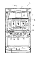
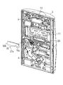
図1及び図2に示すように、遊技機(1)、具体的にはスロットマシンは、前面が開放した筐体(2)と、筐体(2)の左端部前面に上下方向を向く軸回りに開閉可能に枢支された前面扉(3)とを備える。前面扉(3)は、閉状態にあるとき、前面扉(3)に設けられた上下のロック機構(4)が筐体(2)に設けられた係合部(図示略)に係合することにより、所定のキー等を使用しない限り開けられないようになっている。 As shown in FIG. 1 and FIG. 2, the gaming machine (1), specifically, the slot machine, has a housing (2) whose front surface is open, and an axis that faces up and down on the front surface of the left end of the housing (2). A front door (3) pivotally supported to be openable and closable is provided. When the front door (3) is in a closed state, the upper and lower locking mechanisms (4) provided on the front door (3) engage with engaging portions (not shown) provided on the housing (2). Thus, it cannot be opened unless a predetermined key or the like is used.
なお、本発明は、本実施形態において遊技機(1)を遊技媒体がメダルであるスロットマシンとして説明するが、これに代えて、遊技機(1)を遊技媒体がパチンコ玉であるパチンコまたはスロットマシンとしても良い。 In the present embodiment, the gaming machine (1) is described as a slot machine in which the game medium is a medal in this embodiment, but instead, the gaming machine (1) is a pachinko or slot in which the gaming medium is a pachinko ball. It is good as a machine.
筐体(2)内には、外周面に複数種類の図柄、数字等で構成される識別情報が付記された左、中、右3個の回胴体(5a)により形成される表示装置(5)と、遊技媒体であるメダルを貯留及び放出可能なホッパーユニット(6)と、遊技進行を制御するための主制御基板(7)及び副制御基板(8)と、主制御基板(7)の制御信号に基づいて表示装置(5)の回胴体(5a)の回転を制御する回胴体制御基板(9)と、表示装置(5)、ホッパーユニット(6)、及び主制御基板(7)等に電力を供給可能な電源装置(10)が設けられている。 In the casing (2), a display device (5a) is formed by three left, middle, and right rotators (5a) each having identification information composed of a plurality of types of symbols and numerals on the outer peripheral surface. ), A hopper unit (6) capable of storing and releasing medals as game media, a main control board (7) and a sub control board (8) for controlling the progress of the game, and a main control board (7) A rotating body control board (9) for controlling the rotation of the rotating body (5a) of the display device (5) based on the control signal, the display device (5), the hopper unit (6), the main control board (7), etc. A power supply device (10) capable of supplying electric power is provided.
前面扉(3)の前面には、3個の回胴体(5a)の識別情報を左、中、右に表示可能な識別情報表示窓(11)と、識別情報表示窓(11)の上方にあって、前面扉(3)の後面側に取り付けられる液晶表示器(12)に映し出される各種遊技情報を表示可能な液晶表示窓(13)と、各種遊技情報を表示可能な遊技情報表示領域部(14)と、遊技媒体であるメダルを投入可能なメダル投入部(15)と、メダルの賭数を選定するためのベットスイッチボタン(16)と、表示装置(5)の回胴体(5a)を回転させるときに操作されるスタートスイッチレバー(17)と、回胴体(5a)の回転を停止させるときに操作されるストップスイッチボタン(18)等が設けられ、また、同じく後面側には、各種遊技情報を表示可能な複数の発光素子、電気素子等を実装した実装基板(19)が取り付けられている。 On the front of the front door (3), there are an identification information display window (11) capable of displaying identification information of the three rotating bodies (5a) on the left, middle and right, and above the identification information display window (11). A liquid crystal display window (13) capable of displaying various game information displayed on a liquid crystal display (12) attached to the rear side of the front door (3), and a game information display area portion capable of displaying various game information (14), a medal insertion part (15) capable of inserting medals as game media, a bet switch button (16) for selecting the number of medals bet, and a rotating body (5a) of the display device (5) Is provided with a start switch lever (17) that is operated when rotating, a stop switch button (18) that is operated when stopping rotation of the rotating body (5a), etc. A mounting board (19) on which a plurality of light emitting elements, electric elements and the like capable of displaying various game information are mounted is attached.
遊技情報表示領域部(14)は、識別情報表示窓(11)の下方近傍に設けられ、その領域には、左側から上、中、下の3個のベット数表示窓(14a)、メダル払出枚数表示窓(14b)、ボーナスゲーム残数表示窓(14c)、クレジット数表示窓(14d)、上、中、下3個の遊技進行表示窓(14e)が設けられている。 The game information display area (14) is provided near the lower part of the identification information display window (11). The game information display area (14) includes three bet number display windows (14a) from the left, upper, middle, and lower, and a medal payout. There are provided a number display window (14b), a bonus game remaining number display window (14c), a credit number display window (14d), and three upper, middle and lower game progress display windows (14e).
遊技機(1)の遊技は、遊技者がメダルをメダル投入部(15)に所定枚数投入して、ベットスイッチボタン(16)及びスタートスイッチレバー(17)を順次操作することにより、表示装置(5)の各回胴体(5a)を一斉に回転させて所定時間経過後、各回胴体(5a)に対応するストップスイッチボタン(18)を順次操作して、各回胴体(5a)を停止させることにより行われる。なお、メダル投入部(15)にメダルを投入することにより、所定数(例えば、50枚)を上限として、後のゲームまでクレジット数として記憶されるようになっている。 The game of the gaming machine (1) is performed by the player inserting a predetermined number of medals into the medal insertion section (15) and sequentially operating the bet switch button (16) and the start switch lever (17) to display the display device ( 5) Rotate each spinning body (5a) at the same time, and after a predetermined time has elapsed, operate the stop switch button (18) corresponding to each spinning body (5a) in sequence to stop each spinning body (5a). Is called. Note that by inserting medals into the medal insertion unit (15), a predetermined number (for example, 50) is used as an upper limit, and the number of credits is stored until a later game.
そして、各回胴体(5a)が停止したときの、識別情報表示窓(11)に表示される左、中、右の識別情報の組み合わせにより、入賞の有無、及び賞の大小に応じたメダルの配当枚数が決定され、入賞した場合には、大当りとなって、予め定めた入賞枚数分だけホッパーユニット(6)からメダルが払い出される。大当りとなった場合には、予め定めたボーナスゲームに移行して、遊技者は短時間に大量のメダルを得ることができる。 Then, according to the combination of the left, middle, and right identification information displayed in the identification information display window (11) when each torso (5a) stops, the medal payout according to the presence / absence of a prize and the size of the prize When the number is determined and a prize is won, a big hit is made, and medals are paid out from the hopper unit (6) by a predetermined number of prizes. In the case of a big win, the game proceeds to a predetermined bonus game, and the player can obtain a large number of medals in a short time.
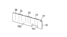
実装基板(19)は、遊技情報表示領域部(14)に対応する前面扉(3)の裏面側に設けられた前向き凹状の取付部(20)にねじ(20a)をもって固定されるとともに、前面(前面扉(3)の後面に対向する面)(19a)には、発光素子をなすメダルのベット数(賭数)を点灯表示する3個の発光ダイオード(21)と、入賞したときのメダルの払出枚数を表示する7セグメント発光ダイオードLED(22)と、ボーナスゲームに移行したときのボーナスゲーム残数を表示する7セグメント発光ダイオード(23)と、クレジット数を表示する7セグメント発光ダイオード(24)と、スタート可能状態、メダル投入可能状態、リプレイ状態等の遊技状況を点灯表示する3個の発光ダイオード(25)と、電気素子をなす抵抗(27)及びコンデンサ(28)と、主制御基板(7)と実装基板(19)とを接続するハーネス(29)のコネクタ(29a)が接続される基板用コネクタ(26)とが実装される。すなわち、実装基板(19)の前面(19a)は実装面を形成し、後面(19b)は半田付け面を形成する。また、実装基板(19)の前面(19a)には、プリント配線が施される。 The mounting board (19) is fixed to the front concave mounting portion (20) provided on the back surface side of the front door (3) corresponding to the game information display area portion (14) with a screw (20a). (Surface facing the rear surface of the front door (3)) (19a) includes three light-emitting diodes (21) that light up and display the number of bets (number of bets) of the medals that make up the light-emitting elements, and the medals when winning 7-segment light-emitting diode LED (22) for displaying the number of payouts, 7-segment light-emitting diode (23) for displaying the remaining number of bonus games when the bonus game is entered, and 7-segment light-emitting diode (24) for displaying the number of credits ), Three light-emitting diodes (25) that light up and display the gaming status such as startable state, medal insertion possible state, replay state, etc., resistor (27) and capacitor (28) that make up electrical elements, and main control board (7) to connect the mounting board (19) Board connector nest (29) connector (29a) is connected to (26) are mounted. That is, the front surface (19a) of the mounting substrate (19) forms a mounting surface, and the rear surface (19b) forms a soldering surface. Also, printed wiring is applied to the front surface (19a) of the mounting substrate (19).
発光ダイオード(21)、7セグメント発光ダイオード(22)、(23)、(24)及び発光ダイオード(25)は、遊技情報表示領域部(14)のベット数表示窓(14a)、メダル払出数表示窓(14b)、ボーナスゲーム残数表示窓(14c)、クレジット数表示窓(14d)及び遊技進行表示窓(14e)にそれぞれ対応し、それぞれが発光することにより、各種遊技情報を各窓を通して、その旨を前面扉(3)の前面に表示する。 Light-emitting diode (21), 7-segment light-emitting diodes (22), (23), (24) and light-emitting diode (25) are a game information display area (14) bet number display window (14a), medal payout number display It corresponds to the window (14b), the bonus game remaining number display window (14c), the credit number display window (14d), and the game progress display window (14e), and each emits light so that various game information can be passed through each window. A message to that effect is displayed on the front of the front door (3).
基板用コネクタ(26)は、ハーネス(29)のコネクタ(29a)が差し込まれる差込口(26a)が下方へ向くように実装基板(19)の前面(19a)下部に実装される。実装基板(19)における基板用コネクタ(26)が実装される位置の下方には、ハーネス(29)が実装基板(19)の前面(19a)側から後面(19b)側へ挿通可能な切欠部(19c)が設けられている。 The board connector (26) is mounted on the lower part of the front surface (19a) of the mounting board (19) so that the insertion port (26a) into which the connector (29a) of the harness (29) is inserted faces downward. Below the position where the board connector (26) is mounted on the mounting board (19), a notch that allows the harness (29) to be inserted from the front surface (19a) side to the rear surface (19b) side of the mounting board (19) (19c) is provided.
上述により、実装基板(19)の前面(19a)を実装面とし、この実装面に、発光素子をなす発光ダイオード(21)(25)、7セグメント発光ダイオード(22)(23)(24)、及び電気素子をなす抵抗(27)、コンデンサ(28)、並びに基板用コネクタ(26)の全ての実装部品が実装されることにより、実装基板(19)の半田付け面を後面(19b)の片面のみとすることができ、自動機による半田付けを容易に行うことができ、実装基板(19)の製作コストを大幅に削減することが可能となる。 As described above, the front surface (19a) of the mounting substrate (19) is used as a mounting surface, and light emitting diodes (21) and (25), 7 segment light emitting diodes (22), (23), and (24) that form light emitting elements are formed on the mounting surface. In addition, the mounting surface of the mounting board (19) is changed to one side of the rear surface (19b) by mounting all mounting parts of the resistor (27), the capacitor (28), and the board connector (26) forming the electrical elements. Therefore, soldering by an automatic machine can be easily performed, and the manufacturing cost of the mounting board (19) can be greatly reduced.
また、基板用コネクタ(26)を実装基板(19)の下部に下向きに実装したことにより、基板用コネクタ(26)に接続されるハーネス(29)の配線の向きを下向きにすることができる。これにより、ハーネス(29)が発光素子に干渉したり、実装基板(19)の上方近傍に位置する識別情報表示窓(11)に露呈したりすることがないので、ハーネス(29)の配線が容易となり、実装基板(19)の取り付けを容易に行うことができる。さらには、基板用コネクタ(26)に接続されるハーネス(29)を、実装基板(19)に設けた切欠部(19c)を通して、実装基板(19)の前面(19a)側から後面(19b)側へ簡単に配線することができる。 Further, by mounting the board connector (26) downward on the lower part of the mounting board (19), the wiring of the harness (29) connected to the board connector (26) can be turned downward. This prevents the harness (29) from interfering with the light emitting element or being exposed to the identification information display window (11) located near the upper part of the mounting board (19). This makes it easy to attach the mounting board (19). Further, the harness (29) connected to the board connector (26) passes through the notch (19c) provided on the mounting board (19), and the rear surface (19b) from the front surface (19a) side of the mounting board (19). Easy wiring to the side.
(1)遊技機
(2)筐体
(3)前面扉
(4)ロック機構
(5)表示装置
(5a)回胴体
(6)ホッパーユニット
(7)主制御基板
(8)副制御基板
(9)回胴体制御基板
(10)電源装置
(11)識別情報表示窓
(12)液晶表示器
(13)液晶表示窓
(14)遊技情報表示領域部
(14a)ベット数表示窓(表示窓)
(14b)メダル払出数表示窓(表示窓)
(14c)ボーナスゲーム残数表示窓(表示窓)
(14d)クレジット数表示窓(表示窓)
(14e)遊技進行表示窓(表示窓)
(15)メダル投入部
(16)ベットスイッチボタン
(17)スタートスイッチレバー
(18)ストップスイッチボタン
(19)実装基板
(19a)前面(実装面)
(19b)後面(半田付け面)
(19c)切欠部
(20)取付部
(20a)ねじ
(21)発光ダイオード(発光素子)
(22)(23)(24)7セグメント発光ダイオード(発光素子)
(25)発光ダイオード(発光素子)
(26)基板用コネクタ
(26a)差込口
(27)抵抗(電気素子)
(28)コンデンサ(電気素子)
(29)ハーネス
(29a)コネクタ
(1) Pachislot machines
(2) Housing
(3) Front door
(4) Lock mechanism
(5) Display device
(5a) Revolver
(6) Hopper unit
(7) Main control board
(8) Sub control board
(9) Revolute control board
(10) Power supply
(11) Identification information display window
(12) Liquid crystal display
(13) LCD display window
(14) Game information display area
(14a) Bet number display window (display window)
(14b) Medal payout number display window (display window)
(14c) Bonus game remaining number display window (display window)
(14d) Credit number display window (display window)
(14e) Game progress display window (display window)
(15) Medal insertion part
(16) Bet switch button
(17) Start switch lever
(18) Stop switch button
(19) Mounting board
(19a) Front (mounting surface)
(19b) Rear surface (soldering surface)
(19c) Notch
(20) Mounting part
(20a) Screw
(21) Light emitting diode (light emitting element)
(22) (23) (24) 7-segment light emitting diode (light emitting device)
(25) Light emitting diode (light emitting element)
(26) Board connector
(26a) outlet
(27) Resistance (electric element)
(28) Capacitor (electrical element)
(29) Harness
(29a) Connector
Claims (3)
前記実装基板の前面に、電気素子、及び前記制御基板と前記実装基板とを接続するハーネスのコネクタが接続される基板用コネクタを実装したことを特徴とする遊技機。 A mounting board is attached to the rear surface of the front door provided on the front surface of the housing so as to be opened and closed, and predetermined game information is provided on the front surface of the mounting board based on a control signal of a control board provided in the housing. In a gaming machine equipped with a light emitting element that can be displayed on the front surface of the front door through a display window provided on the front door,
A gaming machine, wherein a board connector to which an electrical element and a harness connector for connecting the control board and the mounting board are connected is mounted on the front surface of the mounting board.
3. The gaming machine according to claim 2, wherein a notch portion into which a harness connected to the board connector is inserted is provided below a position where the board connector is mounted on the mounting board.
Priority Applications (1)
| Application Number | Priority Date | Filing Date | Title |
|---|---|---|---|
| JP2004109366A JP2005287902A (en) | 2004-04-01 | 2004-04-01 | Game machine |
Applications Claiming Priority (1)
| Application Number | Priority Date | Filing Date | Title |
|---|---|---|---|
| JP2004109366A JP2005287902A (en) | 2004-04-01 | 2004-04-01 | Game machine |
Publications (1)
| Publication Number | Publication Date |
|---|---|
| JP2005287902A true JP2005287902A (en) | 2005-10-20 |
Family
ID=35321501
Family Applications (1)
| Application Number | Title | Priority Date | Filing Date |
|---|---|---|---|
| JP2004109366A Pending JP2005287902A (en) | 2004-04-01 | 2004-04-01 | Game machine |
Country Status (1)
| Country | Link |
|---|---|
| JP (1) | JP2005287902A (en) |
Cited By (1)
| Publication number | Priority date | Publication date | Assignee | Title |
|---|---|---|---|---|
| JP2015134178A (en) * | 2015-02-24 | 2015-07-27 | 株式会社ソフイア | Game machine |
Citations (7)
| Publication number | Priority date | Publication date | Assignee | Title |
|---|---|---|---|---|
| JPS61198699A (en) * | 1985-02-27 | 1986-09-03 | 株式会社東芝 | Mounting of circuit board |
| JPS61203695A (en) * | 1985-03-06 | 1986-09-09 | シャープ株式会社 | Part mounting system for single-side wiring board |
| JPH057282U (en) * | 1991-07-12 | 1993-02-02 | 奥村遊機株式會社 | Pachinko machine |
| JPH06304295A (en) * | 1993-04-28 | 1994-11-01 | Yamasa Kk | Slot machine |
| JP2000300721A (en) * | 1991-10-29 | 2000-10-31 | Sophia Co Ltd | Slot machine |
| JP2001113005A (en) * | 1999-10-19 | 2001-04-24 | Toyomaru Industry Co Ltd | Game machine |
| JP2001161931A (en) * | 1999-12-06 | 2001-06-19 | Newgin Corp | Controller for large premium device |
-
2004
- 2004-04-01 JP JP2004109366A patent/JP2005287902A/en active Pending
Patent Citations (7)
| Publication number | Priority date | Publication date | Assignee | Title |
|---|---|---|---|---|
| JPS61198699A (en) * | 1985-02-27 | 1986-09-03 | 株式会社東芝 | Mounting of circuit board |
| JPS61203695A (en) * | 1985-03-06 | 1986-09-09 | シャープ株式会社 | Part mounting system for single-side wiring board |
| JPH057282U (en) * | 1991-07-12 | 1993-02-02 | 奥村遊機株式會社 | Pachinko machine |
| JP2000300721A (en) * | 1991-10-29 | 2000-10-31 | Sophia Co Ltd | Slot machine |
| JPH06304295A (en) * | 1993-04-28 | 1994-11-01 | Yamasa Kk | Slot machine |
| JP2001113005A (en) * | 1999-10-19 | 2001-04-24 | Toyomaru Industry Co Ltd | Game machine |
| JP2001161931A (en) * | 1999-12-06 | 2001-06-19 | Newgin Corp | Controller for large premium device |
Cited By (1)
| Publication number | Priority date | Publication date | Assignee | Title |
|---|---|---|---|---|
| JP2015134178A (en) * | 2015-02-24 | 2015-07-27 | 株式会社ソフイア | Game machine |
Similar Documents
| Publication | Publication Date | Title |
|---|---|---|
| JP7219395B2 (en) | game machine | |
| JP2004267357A (en) | Slot machine | |
| JP5396423B2 (en) | Game machine | |
| JP2006325891A (en) | Game machine | |
| JPH11137798A (en) | Prize ball dispensing device of ball shooting game machine | |
| JP4263916B2 (en) | Slot machine | |
| JP4347827B2 (en) | Game machine | |
| JP2004057332A (en) | Slot machine | |
| JP2004057310A (en) | Slot machine | |
| JP2011115210A (en) | Game machine | |
| JP2010000147A (en) | Game machine | |
| JP2004057331A (en) | Slot machine | |
| JP2005287902A (en) | Game machine | |
| JP7206480B2 (en) | Decorative parts for game machines | |
| JP2009131390A (en) | Game machine | |
| JP2008245818A (en) | Game machine | |
| JP4410115B2 (en) | Game machine | |
| JP5777071B2 (en) | Game machine | |
| JP2008054729A (en) | Game machine | |
| JP7219394B2 (en) | game machine | |
| JP7206479B2 (en) | Decorative parts for game machines | |
| JP5019587B2 (en) | Gaming machines and slot machines | |
| JP7206478B2 (en) | Decorative parts for game machines | |
| JP2008183155A (en) | Game machine | |
| JP2007007289A (en) | Performance device of game machine |
Legal Events
| Date | Code | Title | Description |
|---|---|---|---|
| A621 | Written request for application examination |
Free format text: JAPANESE INTERMEDIATE CODE: A621 Effective date: 20070129 |
|
| A977 | Report on retrieval |
Free format text: JAPANESE INTERMEDIATE CODE: A971007 Effective date: 20091111 |
|
| A131 | Notification of reasons for refusal |
Free format text: JAPANESE INTERMEDIATE CODE: A131 Effective date: 20091201 |
|
| A521 | Written amendment |
Free format text: JAPANESE INTERMEDIATE CODE: A523 Effective date: 20100127 |
|
| A02 | Decision of refusal |
Free format text: JAPANESE INTERMEDIATE CODE: A02 Effective date: 20100803 |
|
| A521 | Written amendment |
Free format text: JAPANESE INTERMEDIATE CODE: A523 Effective date: 20101028 |
|
| A911 | Transfer of reconsideration by examiner before appeal (zenchi) |
Free format text: JAPANESE INTERMEDIATE CODE: A911 Effective date: 20101104 |
|
| A912 | Removal of reconsideration by examiner before appeal (zenchi) |
Free format text: JAPANESE INTERMEDIATE CODE: A912 Effective date: 20110204 |